

Page 1
VTM-TLM191
19” & 24” Professional LED Monitors with
HDMI, VGA, and Looping BNC
VITEK
VITEK
VTM-TLM241
FEATURES
• 19.5” & 23.6” Wide Screen LED Display Panel
• HDMI, VGA, and Looping BNC Composite Video Inputs & Stereo Audio
Input
• Resolution up to 1920 x 1080 (1080P)
• Contrast Ratio of 10,000:1
• <5ms Response time
• 170° Horizontal Viewing Angle
• Front Panel Controls
• VESA Standard Mounting
• Professional grade display designed for 24/7 continuous use in security
applications with 50,000 Hour Panel Life
Page 2

Table of contents
IMPORTANT SAFETY INFORMATION
ENVIRONMENT
• Do not install the monitor outdoors or in any hostile environment. To
prevent fire or electric shock, do not expose monitor to rain or
moisture. Avoid placing the monitor in areas subject to extreme
temperature such as direct sunlight or near a heating
appliances/equipment (such as amplifiers, etc) as this may result in
overheating and damage.
• This monitor is designed to be used in the office or home. Do not
subject it to vibrations, dust or corrosive gases.
• To obtain a clear picture, do not expose screen to direct
illumination or sunlight. Using the monitor against a bright background
and where sunlight or other light sources shine directly on to the
monitor can increase eye fatigue
POWER CORD
• Neither the monitor itself nor any other heavy object should rest
on the power cord.
• Protect the power cord from being walked on or pinched
particularly at plugs, convenience receptacles and the point where
they exit from the monitor.
• Firmly grasp the plug when disconnecting the power cord. Do not pull
the power cord itself.
• Do not modify or damage the cord. Damage to a power cord can
cause fire or electric shock.
• This monitor is designed to operate on 100-240V AC supply. Take
caution in connecting it to the correct supply using the correct power
cord.
MOUNTING
• Always place the monitor on a secure table or have it properly
mounted to the wall. Do not hang anything on the monitor
.
• Ensure the monitor is located close to a power outlet that is easily
accessible, as removing the power cord is the only way to isolate
power
Important safety information 2
In The Box 4
Connections 4
On-Screen Display (OSD) Operation 7
Rear interface 4
Control Layout 5
How to connect your monitor 5
AV Input Configuration 7
HDMI Input Configuration 9
VGA Input Configuration 12
2
Page 3

IMPORTANT SAFETY INFORMATION
ENVIRONMENT
• Do not install the monitor outdoors or in any hostile environment. To
prevent fire or electric shock, do not expose monitor to rain or
moisture. Avoid placing the monitor in areas subject to extreme
temperature such as direct sunlight or near a heating
appliances/equipment (such as amplifiers, etc) as this may result in
overheating and damage.
• This monitor is designed to be used in the office or home. Do not
subject it to vibrations, dust or corrosive gases.
• To obtain a clear picture, do not expose screen to direct
illumination or sunlight. Using the monitor against a bright background
and where sunlight or other light sources shine directly on to the
monitor can increase eye fatigue
POWER CORD
MOUNTING
• Neither the monitor itself nor any other heavy object should rest
on the power cord.
• Protect the power cord from being walked on or pinched
particularly at plugs, convenience receptacles and the point where
they exit from the monitor.
• Firmly grasp the plug when disconnecting the power cord. Do not pull
the power cord itself.
• Do not modify or damage the cord. Damage to a power cord can
cause fire or electric shock.
• This monitor is designed to operate on 100-240V AC supply. Take
caution in connecting it to the correct supply using the correct power
cord.
• Always place the monitor on a secure table or have it properly
mounted to the wall. Do not hang anything on the monitor
• Ensure the monitor is located close to a power outlet that is easily
accessible, as removing the power cord is the only way to isolate
power
.
Page 4

IN THE BOX
1 x LCD Monitor, 1 x AC adapter, 1 x VGA cable, 1 x Audio cable, 1 x User
Manual
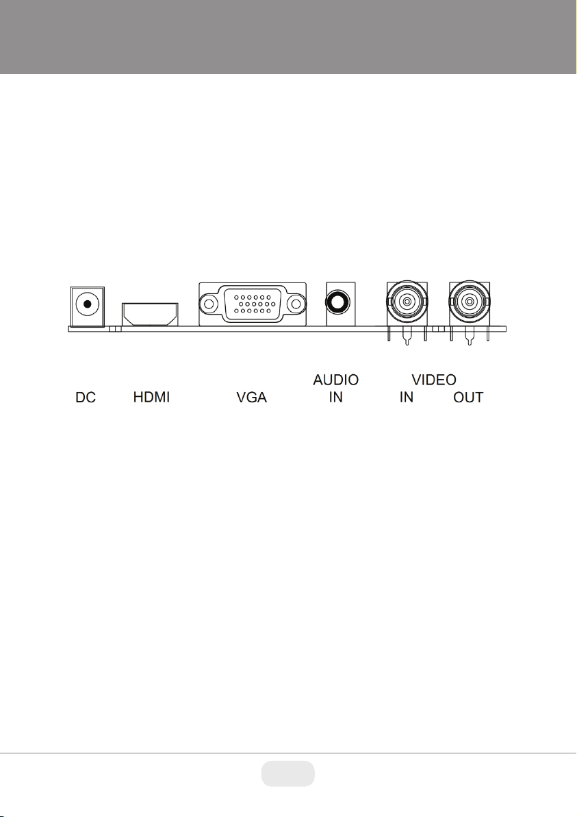
CONNECTIONS
Rear Interface
DC: Only use the 12v DC power supply included with the monitor.
HDMI: (High-Definition Multimedia Interface) supports digital video and audio
connections.
VG A: 15 pin D-sub cable for standard VGA connection.
Audio IN:
3.5 mm stereo jack connection for audio input when using VGA /AV
connector.
VIDEO/AV IN:
BNC connections supporting composite video inputs from equipment
such as Cameras or DVR’s.
VIDEO/AV OUT :
Composite video loop though output – connect a second monitor.
USING A WALL MOUNT
Caution: Any wall mount must bear a minimum of 5x the monitor’s net weight
to mount safely. The stand must be removed first before mounting this way.
1. Place the monitor face down on a surface that is soft, yet strong
STORAGE
VENTILATION
WATER AND MOISTURE
CLEANING
enough to hold the monitor.
2. Use a screwdriver to remove the screws from the four holes on each
side of the bottom of the monitor’s base.
3. Make sure all cables are already connected to the monitor.
4. Follow the directions included with the wall mount to fix the monitor to
the wall.
• Unplug the monitor when unused for long periods of time.
• Never cover or block the ventilation slots in the monitor. A minimum
distance of at least 4” inches should be maintained around the unit for
sufficient ventilation.
• Never insert any foreign object, metal or liquid into the ventilation
slots, as this could result in fire or electric shock.
• Avoid installing a DVR or other equipment too close to the
monitor. Keep such equipment at least 12” inches away from the
monitor.
• The monitor should not be exposed to any moisture or liquid.
• Do not use the monitor near water.
• Do not touch the monitor or cable with wet hands as this may cause
electric shock or damage.
• Unplug the unit from the wall outlet before cleaning.
• Do not use liquid or aerosol cleaners. Use a dry soft lint-free cloth for
cleaning. If dust is persistent, wipe with a slightly damp cloth.
4
Page 5
IN THE BOX
1 x LCD Monitor, 1 x AC adapter, 1 x VGA cable, 1 x Audio cable, 1 x User
Manual
CONNECTIONS
Rear Interface
DC: Only use the 12v DC power supply included with the monitor.
HDMI: (High-Definition Multimedia Interface) supports digital video and audio
connections.
VG A: 15 pin D-sub cable for standard VGA connection.
Audio IN:
3.5 mm stereo jack connection for audio input when using VGA /AV
connector.
VIDEO/AV IN:
BNC connections supporting composite video inputs from equipment
such as Cameras or DVR’s.
VIDEO/AV OUT :
Composite video loop though output – connect a second monitor.
Page 6

CONTROL LAYOUT
POWER
If audio input is required, connect the audio (red and white) cables to
the AUDIO INPUT R and L connectors on the rear of the monitor and
to the Audio Output connector on the DVR/Camera etc.
Connect power to the monitor and video source, and switch on. Using
the SOURCE button, press repeatedly until either ‘AV1’ or ‘AV2’
(depending on the connection used) is highlighted on the display at
the top of the monitor's screen, and press ‘+’ to select.
2. Connecting using HDMI
Connect one end of a HDMI cable (not supplied) to the HDMI
connector on the rear of the monitor, and the other to the HDMI out
connector on the PC/DVR. This connection will support both video and
audio transmission.
Connect power to the monitor and video source, and switch on. Using
the SOURCE button, press repeatedly until ‘HDMI’ is highlighted on
the display at the top of the monitor's screen, and press ‘+’ to select.
3. Connecting using VGA
Connect one end of a 15-pin monitor cable to the VGA connector on
the monitor and the other end to the PC/DVR. Note - if your PC/DVR
connector isn't 15-pin D-sub you may need an adapter to connect
with this cable.
If audio is required, connect one end of the 3.5 mm stereo audio cable
(sometimes referred to as 1/8" stereo jack) to the PC Audio IN
connector on the back of the monitor and the other end to the audio
output on the PC/DVR.
Connect power to the monitor and video source, and switch on. Using
the SOURCE button, press repeatedly until ‘VGA’ is highlighted on the
display at the top of the monitor's screen, and press ‘+’ to select.
Ensure all cable connections are secure - tighten all cable screws.
Movement and vibration may dislodge cables that are improperly
connected. Route all wiring and cabling away from any heat sources
and sharp metal edges to avoid damage.
The control buttons are located on the right hand rear side of the monitor.
5keys series
7keys series
SOURCE
SOURCE: Selects input mode – AV, HDMI, VGA.
MENU: Access to the On Screen Display (OSD) menu.
+
POWER: Turns the monitor on or off.
HOW TO CONNECT YOUR MONITOR
SOURCE - + MENU
and -: Volume controls up/down, confirm input source selection
1. Connecting using AV - Composite Video
Connect your video cable with BNC connector to either the AV1 or
AV2 connector on the rear of the monitor, and the other end to your
DVR/Camera etc.
- + ∨ ∧ MENU POWER
and navigation in the OSD.
6
Page 7

If audio input is required, connect the audio (red and white) cables to
the AUDIO INPUT R and L connectors on the rear of the monitor and
to the Audio Output connector on the DVR/Camera etc.
Connect power to the monitor and video source, and switch on. Using
the SOURCE button, press repeatedly until either ‘AV1’ or ‘AV2’
(depending on the connection used) is highlighted on the display at
the top of the monitor's screen, and press ‘+’ to select.
2. Connecting using HDMI
Connect one end of a HDMI cable (not supplied) to the HDMI
connector on the rear of the monitor, and the other to the HDMI out
connector on the PC/DVR. This connection will support both video and
audio transmission.
Connect power to the monitor and video source, and switch on. Using
the SOURCE button, press repeatedly until ‘HDMI’ is highlighted on
the display at the top of the monitor's screen, and press ‘+’ to select.
3. Connecting using VGA
Connect one end of a 15-pin monitor cable to the VGA connector on
the monitor and the other end to the PC/DVR. Note - if your PC/DVR
connector isn't 15-pin D-sub you may need an adapter to connect
with this cable.
If audio is required, connect one end of the 3.5 mm stereo audio cable
(sometimes referred to as 1/8" stereo jack) to the PC Audio IN
connector on the back of the monitor and the other end to the audio
output on the PC/DVR.
Connect power to the monitor and video source, and switch on. Using
the SOURCE button, press repeatedly until ‘VGA’ is highlighted on the
display at the top of the monitor's screen, and press ‘+’ to select.
Ensure all cable connections are secure - tighten all cable screws.
Movement and vibration may dislodge cables that are improperly
connected. Route all wiring and cabling away from any heat sources
and sharp metal edges to avoid damage.
Page 8

SHARPNESS: (0-100)
COLOR TEMP: Select the color temperature. (Normal/Warm/Cool)
PICTURE MODE: Select defaults or save user setting. (
User/Standard/Soft/Vivid)
2. OSD
LANGUAGE: Select preferred language for OSD.
(En/Ch/Ger/Fr/Sp/It/Pt/Pl/Ru)
H-POSITION: (0-100) Set the horizontal position of the OSD.
V-POSITION: (0-100) Set the vertical position of the OSD.
DURATION: (5-60) Set seconds for the OSD to automatically
close.
BACKLIGHT: Set power level in use by backlight (HIGH/MID/LOW)
MEM-RECALL: Restore all factory defaults.
3. Function
HSTART: Set left alignment point of image.
HSIZE: Set horizontal size of image.
VSTART: Set lower alignment point of image.
VSIZE: Set vertical size of image.
1. To access the OSD Menu press ‘MENU’.
2. Use the ‘+’ or ‘-’ buttons to select the required menu item, then press
the ‘SOURCE’ button to select the Sub menu.
3. Continue to use the ‘SOURCE’ button to highlight the required field, then
press ‘+’ or ‘-’ to adjust the setting.
4. Press the ‘MENU’ button to return to previous menu.
5. Press the ‘MENU’ button again to exit the OSD Menu completely.
6. N.B. To Lock or Unlock OSD settings after set up.
Press and hold "menu" button for 5 seconds.
The layout of the OSD will change depending on the input
AV - Input Configuration
1. Picture
BASIC ON-SCREEN DISPLAY SETUP
that is selected.
CONTRAST: (0–100) Set the difference between the light and dark
areas of the picture.
BRIGHTNESS: (0–100) Set how bright the display is.
HUE: -50 to +50 (only available if NTSC)
SATURATION: (0-100)
8
Page 9

SHARPNESS: (0-100)
COLOR TEMP: Select the color temperature. (Normal/Warm/Cool)
PICTURE MODE: Select defaults or save user setting. (
User/Standard/Soft/Vivid)
2. OSD
LANGUAGE: Select preferred language for OSD.
(En/Ch/Ger/Fr/Sp/It/Pt/Pl/Ru)
H-POSITION: (0-100) Set the horizontal position of the OSD.
V-POSITION: (0-100) Set the vertical position of the OSD.
DURATION: (5-60) Set seconds for the OSD to automatically
close.
BACKLIGHT: Set power level in use by backlight (HIGH/MID/LOW)
MEM-RECALL: Restore all factory defaults.
3. Function
HSTART: Set left alignment point of image.
HSIZE: Set horizontal size of image.
VSTART: Set lower alignment point of image.
VSIZE: Set vertical size of image.
Page 10

4. Audio
COLOR TEMP: Select the color temperature Menu.
COLOR TEMP: Select color temperature preset.
USER - R: Set RED color level.
USER - G: Set GREEN color level.
USER - B: Set BLUE color level.
2. OSD
LANGUAGE: Select preferred language for OSD.
(En/Ch/Ger/Fr/Sp/It/Pt/Pl/Ru)
H-POSITION: (0-100) Set the horizontal position of the OSD.
V-POSITION: (0-100) Set the vertical position of the OSD.
DURATION: (5-60) Set seconds for the OSD to automatically
close.
BACKLIGHT: Set power level in use by backlight (HIGH/MID/LOW)
MEM-RECALL: Restore all factory defaults.
BASS: (0-100)
TREBLE: (0-100)
BALANCE: (-50 to +50)
SOUND MODE: Set user or preset audio configurations.
AVC: (ON/OFF) Automatic Volume Control
(User/Standard/Movie/Music)
HDMI - Input Configuration
1. Picture
CONTRAST: (0–100) Set the difference between the light and dark
BRIGHTNESS: (0–100) Set how bright the display is.
areas of the picture.
10
Page 11

COLOR TEMP: Select the color temperature Menu.
COLOR TEMP: Select color temperature preset.
USER - R: Set RED color level.
USER - G: Set GREEN color level.
USER - B: Set BLUE color level.
2. OSD
LANGUAGE: Select preferred language for OSD.
(En/Ch/Ger/Fr/Sp/It/Pt/Pl/Ru)
H-POSITION: (0-100) Set the horizontal position of the OSD.
V-POSITION: (0-100) Set the vertical position of the OSD.
DURATION: (5-60) Set seconds for the OSD to automatically
close.
BACKLIGHT: Set power level in use by backlight (HIGH/MID/LOW)
MEM-RECALL: Restore all factory defaults.
Page 12

3. Function
VGA - Input Configuration
1. Picture
CONTRAST: (0–100) Set the difference between the light and dark
areas of the picture.
BRIGHTNESS: (0–100) Set how bright the display is.
COLOR TEMP: Select the color temperature Menu.
COLOR TEMP: Select color temperature preset.
USER - R: Set RED color level.
USER - G: Set GREEN color level.
USER - B: Set BLUE color level.
HSTART: Set left alignment point of image.
HSIZE: Set horizontal size of image.
VSTART: Set lower alignment point of image.
VSIZE: Set vertical size of image.
4. Audio
BASS: (0-100)
TREBLE: (0-100)
BALANCE: (-50 to +50)
SOUND MODE: Set user or preset audio configurations.
AVC: (ON/OFF) Automatic Volume Control
(User/Standard/Movie/Music)
12
Page 13

VGA - Input Configuration
1. Picture
CONTRAST: (0–100) Set the difference between the light and dark
areas of the picture.
BRIGHTNESS: (0–100) Set how bright the display is.
COLOR TEMP: Select the color temperature Menu.
COLOR TEMP: Select color temperature preset.
USER - R: Set RED color level.
USER - G: Set GREEN color level.
USER - B: Set BLUE color level.
Page 14

bars of noise are still present, this setting can be used
to remove them.
PHASE: If the phase of your monitor is not fine-tuned, you may
observe the image being unstable in the horizontal
axis. Use this option to manually correct.
AUTO ADJUST : Perform an automatic configuration of the Phase,
Clock, vertical and horizontal position.
4. Audio
BASS: (0-100)
TREBLE: (0-100)
BALANCE: (-50 to +50)
SOUND MODE: Set user or preset audio configurations.
(User/Standard/Movie/Music)
AVC: (ON/OFF) Automatic Volume Control
2. OSD
LANGUAGE: Select preferred language for OSD.
(En/Ch/Ger/Fr/Sp/It/Pt/Pl/Ru)
H-POSITION: (0-100) Set the horizontal position of the OSD.
V-POSITION: (0-100) Set the vertical position of the OSD.
DURATION: (5-60) Set seconds for the OSD to automatically
close.
BACKLIGHT: Set power level in use by backlight (HIGH/MID/LOW)
MEM-RECALL: Restore all factory defaults.
3. Geometry
H-POSITION: Set horizontal image position.
V-POSITION: Set vertical image position.
CLOCK: Manually adjust clock synchronisation.
(If the clock setting of your image is not fine-tuned, you may observe periodic
vertical bars of video noise on your image. These bars of noise are usually
adjusted out when an Auto Configuration is performed. If the
14
Page 15

bars of noise are still present, this setting can be used
to remove them.
PHASE: If the phase of your monitor is not fine-tuned, you may
observe the image being unstable in the horizontal
axis. Use this option to manually correct.
AUTO ADJUST : Perform an automatic configuration of the Phase,
Clock, vertical and horizontal position.
4. Audio
BASS: (0-100)
TREBLE: (0-100)
BALANCE: (-50 to +50)
SOUND MODE: Set user or preset audio configurations.
(User/Standard/Movie/Music)
AVC: (ON/OFF) Automatic Volume Control
Page 16

LIMITED PRODUCT WARRANTY
VITEK products carry a three (3) year limited warranty. VITEK warrants
to the purchaser that products manufactured by VITEK are free of any
rightful claim of infringement or the like, and when used in the manner
intended, will be free of defects in materials and workmanship for a
period of three (3) years, or as otherwise stated above, from the date of
purchase by the end user. This warranty is nontransferable and extends
only to the original buyer or end user customer of a VITEK Authorized
Reseller.
The product must have been used only for its intended purpose, and
not been subjected to damage by misuse, willful or accidental damage,
caused by excessive voltage or lightning.
The product must not have been tampered with in any way or the
guarantee will be considered null and void.
This guarantee does not affect your statutory rights.
Contact your local VITEK Reseller should servicing become necessary.
VITEK makes no warranty or guarantee whatsoever with respect to
products sold or purchased through unauthorized sales channels.
Warranty support is available only if product is purchased through a
VITEK Authorized Reseller.
28492 CONSTELLATION ROAD VALENCIA, CA 91355
WWW.VITEKCCTV.COM
Version 1.0
August 2016
 Loading...