

Page 1

VT-IPS-HDA2
Transcendent Series 4
MegaPixel H.265 HD Video
Server with Intelligent
VITEK
VITEK
FEATURES
• 4MP (2560 x 1440) Real Time Encoding
• 1 BNC Video Input Supporting AHD / TVI / CVI / CVBS
Cameras
• Max. resolution: 2560 x 1440
• Triple Encoding: H.264, H.265, and MJPEG
• Micro SD card for EDGE Recording Supporting pre-alarm &
Auto Cycle Recording
• Fully Programmable Intelligent Analytics including Scene
change, Video Blur, Video Cast, Line Cross, and Intrusion
• 1 Alarm Input / 1 Alarm Output (RS485)
• Supports up to three simultaneous video streams (Individually
Configurable)
• Supports Up The COAX (CoC) Control
• 3 Regions of Interest (ROI)
• Two-Way Audio
• TVS 6000V lightning protection & surge protection
• Applications for iOS® & Android®
• Remote Viewing over the Internet via Web Browser or LAN
• Mac OS® Client & CMS Central Management Software
Included
• 12VDC & PoE Operation
• 3 Year Warranty
Analytics
Page 2

VT-IPS-HDA2
1
n Please use the specified power supply to connect.
n Do not attempt to disassemble the Server; in order to prevent electric shock,
do not remove screws or covers.
n There are no user-serviceable parts inside. Please contact the nearest
service center as soon as possible if there is any failure.
n Avoid incorrect operation, shock, vibration, do not place objects on top of
device which can cause damage to product.
n Do not use corrosive detergent to clean main body of the server. If necessary,
please use soft dry cloth to wipe dirt; for hard contamination, use neutral
detergent. Any cleanser for high grade furniture is applicable.
n Please follow the instructions to install the server.
n Do not operate when temperature, humidity and/or power supply are beyond
the limited stipulations.
n Keep away from heat sources such as radiators, heat registers, stove, etc.
n Do not expose the product to the direct airflow from an air conditioner.
n This is a product instructions only not a quality warranty. We reserve the
rights to amending the typographical errors, inconsistencies with the latest
version, software upgrades and product improvements, interpretation and
modification. These changes will be published in the latest version without
special notification.
n When this product is in use, the relevant contents of Microsoft, Apple and
Google will be used. The pictures and screenshots in this manual are only
used to explain the usage of our product. The ownerships of trademarks,
logos and other intellectual properties related to Microsoft, Apple and Google
belong to the above-mentioned companies.
n This manual is available for many models. Some functions introduced in the
manual may be not available for some models. All pictures and examples
used in the manual are for reference only.
Page 3

2
VT-IPS-HDA2
TABLE OF CONTENTS
1
Introduction ................................................................................................... 3
2 IE Remote Access ......................................................................................... 4
2.1 LAN ..................................................................................................... 4
2.1.1 Access through IP-Tool .......................................................... 4
2.1.2 Directly Access through IE ..................................................... 5
2.2 WAN .................................................................................................... 7
3 Live View ...................................................................................................... 10
4 Remote Configuration ................................................................................. 13
4.1 System Configuration ........................................................................ 13
4.1.1 Basic Information .................................................................. 13
4.1.2 Date and Time ...................................................................... 13
4.1.3 Local Config ......................................................................... 14
4.1.4 Storage ................................................................................. 14
4.2 Image Configuration .......................................................................... 15
4.2.1 Display Configuration ........................................................... 15
4.2.2 Video / Audio Configuration .................................................. 16
4.2.3 OSD Configuration ............................................................... 17
4.2.4 Video Mask ........................................................................... 18
4.2.5 ROI Configuration ................................................................. 18
4.3 PTZ Configuration ............................................................................. 19
4.4 Alarm Configuration .......................................................................... 20
4.4.1 Motion Detection .................................................................. 20
4.4.2 Alarm In ................................................................................ 22
4.4.3 Alarm Out ............................................................................. 23
4.4.4 Alarm Server ........................................................................ 23
4.5 Event Configuration (Optional) .......................................................... 23
4.5.1 Exception .............................................................................. 24
4.5.2 Line Crossing ....................................................................... 25
4.5.3 Intrusion ................................................................................ 28
4.6 Network Configuration ...................................................................... 30
4.6.1 TCP/IP .................................................................................. 30
4.6.2 Port ....................................................................................... 31
4.6.3 Server Configuration ............................................................ 32
4.6.4 DDNS ................................................................................... 32
4.6.5 SNMP ................................................................................... 34
4.6.6 RTSP .................................................................................... 35
4.6.7 UPNP ................................................................................... 36
4.6.8 Email .................................................................................... 36
4.6.9 FTP ....................................................................................... 37
4.7 Security Configuration ....................................................................... 38
4.7.1 User Configuration ............................................................... 38
Page 4
VT-IPS-HDA2
3
4.7.2 Online User .......................................................................... 40
4.7.3 Block and Allow Lists ............................................................ 40
4.8 Maintenance Configuration ............................................................... 40
4.8.1 Backup and Restore ............................................................. 40
4.8.2 Reboot .................................................................................. 41
4.8.3 Upgrade ................................................................................ 41
4.8.4 Operation Log ....................................................................... 42
5 Search .......................................................................................................... 43
5.1 Photo Search .................................................................................... 43
5.2 Video Search .................................................................................... 44
5.2.1 Local Video Search .............................................................. 44
5.2.2 SD Card Video Search ......................................................... 45
6 Appendix ...................................................................................................... 46
Appendix 1 Q & A ............................................................................................... 46
Appendix 2: Specifications ............................................................................... 48
1 Introduction
This high-definition digital video Server (short for DVS) is designed for high
performance CCTV solutions. It adopts state of the art video processing chips. It
utilizes most advanced technologies, such as video encoding and decoding
technology, complies with the TCP/IP protocol, SoC, etc to ensure the system is
more stable and reliable.
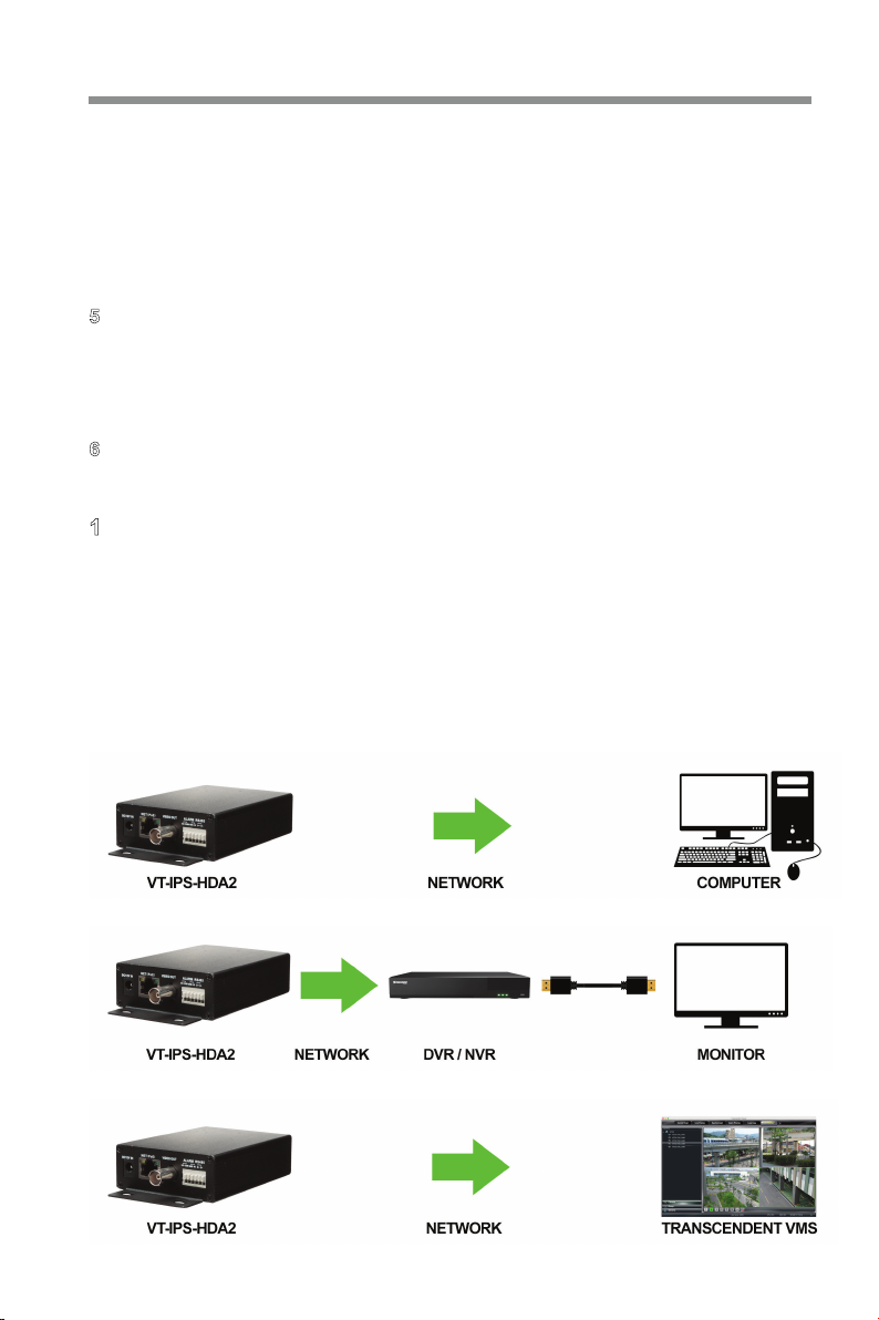
Surveillance Application
Page 5

4
②
③
VT-IPS-HDA2
2 IE Remote Access
You can connect the server via LAN or WAN. The details are as follows:
2.1 LAN
In LAN, there are two ways to access the server: 1. access through IP-Tool; 2.
directly access through IE browser.
2.1.1 Access through IP-Tool
Network connection:
� Make sure the PC and server are connected to the LAN and the IP-Tool is
installed on the PC from the CD.
Double click the IP-Tool icon on the desktop to run this software as shown
below:
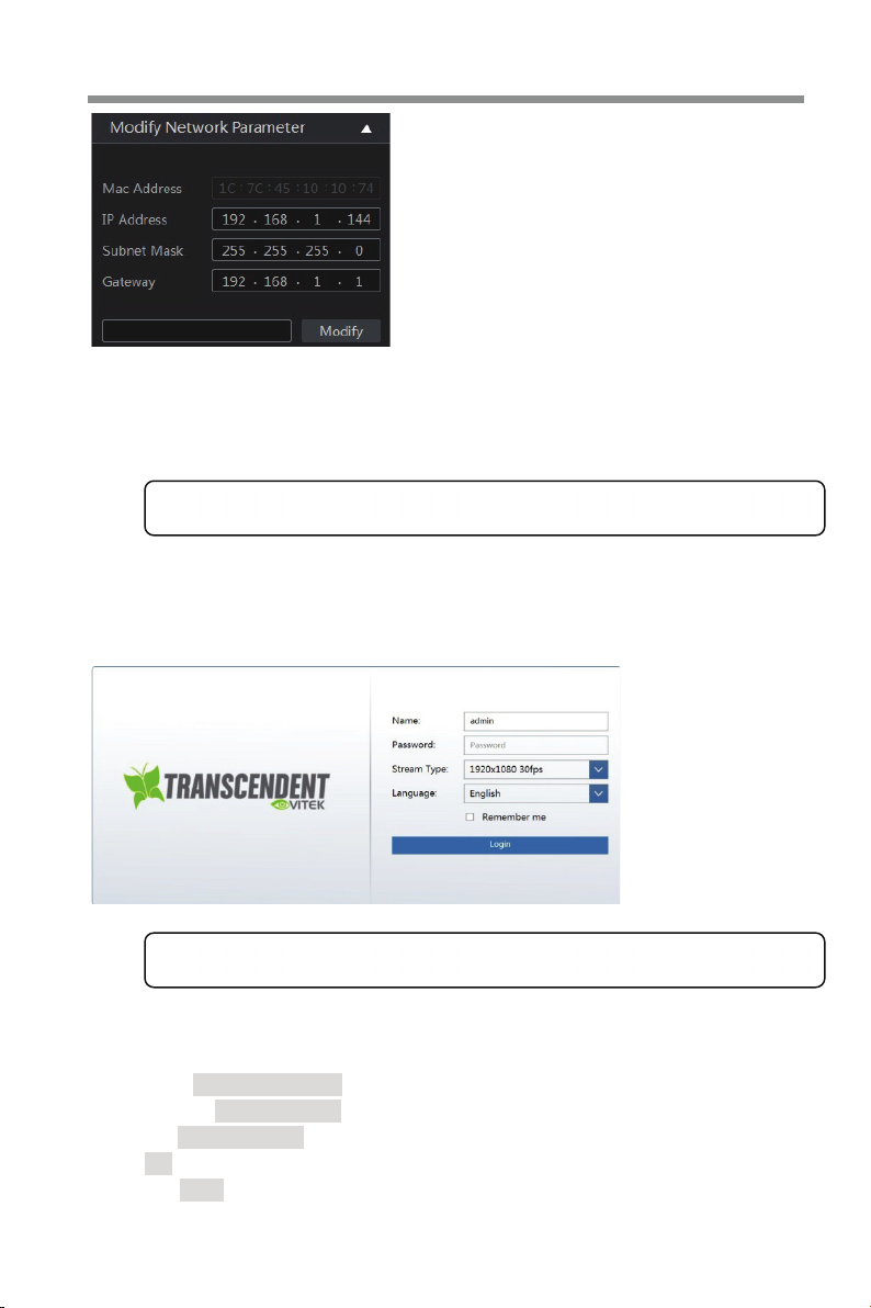
Modify the IP address. The default IP address of this server is 192.168.226.201.
Click the information of the server listed in the above table to show the network
information on the right side. Modify the IP address and gateway of the server and
make sure its network address is in the same local network segment as that of the
computer. Please modify the IP address of your device according to the situation.
Page 6
VT-IPS-HDA2
5
④
For example, the IP address of your computer is 192.168.1.4. So the IP address of
the server should be changed to 192.168.1.X. After modification, please input the
password of the administrator and click “Modify” button to modify the setting.
F
connect to the server. Download the plug-in and run it in your computer if it is the
first time for you to log in. Then input name and password in the login interface.
F
2.1.2 Directly Access through IE
The default network settings are as shown below:
IP address: 192.168.226.201
Subnet Mask: 255.255.255.0
Gateway: 192.168.226.1
HTTP: 80
Data port: 9008
The default password of the administrator is “123456”.
Double click the IP address and then the system will pop up the IE browser to
The default username is “admin”; the default password is “123456”.
Page 7
6
VT-IPS-HDA2
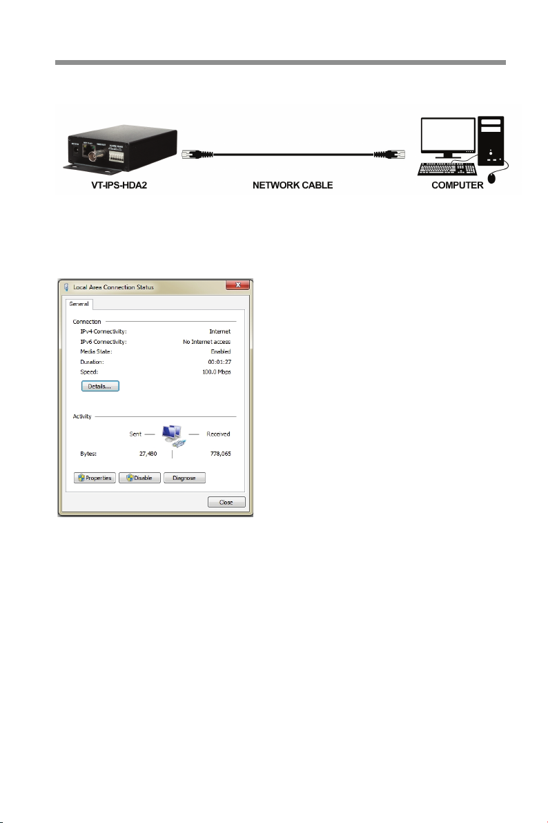
You may use the above default settings when you log into the server for the first
time. You may direct connect the server to the computer through a network cable.
� Manually set the IP address of the PC so the network segment is the same as
the default settings of the IP camera. Open the network and share center. Click
“Local Area Connection” to pop up the following window.
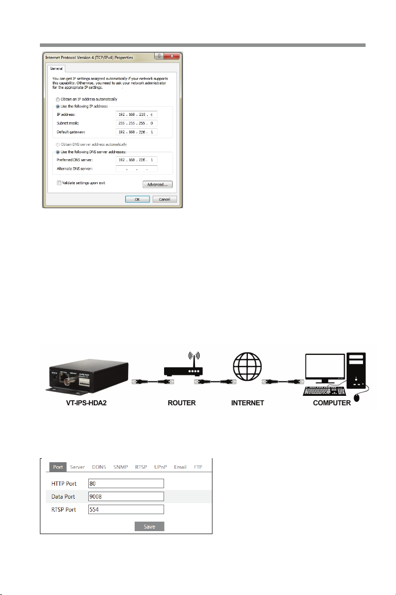
Select “Properties” and then select internet protocol according to the actual
situation (for example: IPv4). Next, click “Properties” button to set the network of
the PC.
Page 8
7
②
③
④
VT-IPS-HDA2
Open IE browser and input the default address of server and confirm, then IE
will download the Active X control automatically.
Download the plug-in and run it in your computer if it is the first time for you to
login.
Input the default username and password and then click Login.
2.2 WAN
Ø Access through the router or virtual server
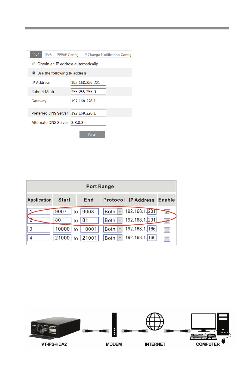
� Make sure the server is connected to the LAN and then log into the server and
go to ConfigàNetworkàPort menu to set the port number.
Port Setup
Page 9
8
②
③
④
VT-IPS-HDA2
Go to Config àNetworkàTCP/IP menu to modify the IP address.
IP Setup
Go to the router’s management interface through IE browser to forward the IP
address and port of the server in the “Virtual Server”.
Router Setup example
Open IE browser and input its WAN IP and http port to access.
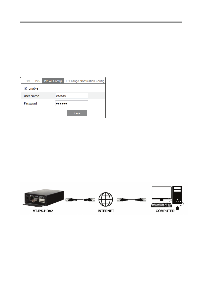
Ø Access through PPPoE dial-up
Network connection
Page 10
9
①
②
③
④
VT-IPS-HDA2
You may access the server through PPPoE auto dial-up. The setting steps are as
follow:
Go to ConfigàNetworkàPort menu to set the port number.
Go to Config àNetworkàTCP/IPàPPPoE Config menu. Enable PPPoE and
then input the user name and password which you can get from your internet
service provider.
Go to Config àNetworkàDDNS menu. Before you configure the DDNS, please
apply for a domain name first. Please refer to DDNS configuration for detailed
information.
Open IE browser and input the domain name and http port to access.
Ø Access through static IP
Network connection
The setting steps are as follow:
� Go to ConfigàNetworkàPort menu to set the port number.
② Go to Config àNetworkàTCP/IP menu to set the IP address. Check “Use the
following IP address” and then input the static IP address and other parameters.
③ Open IE browser and input its WAN IP and http port to access.
Page 11
10
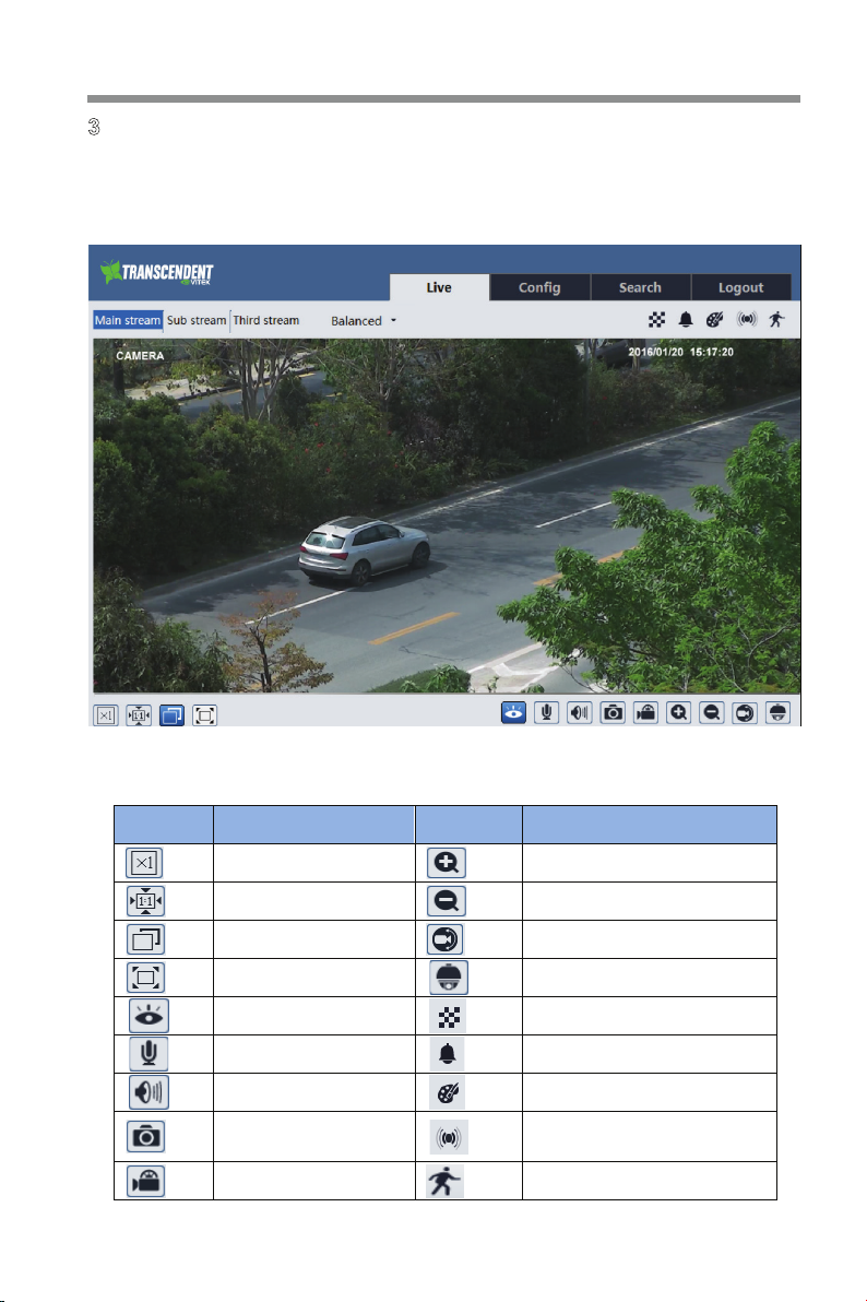
3 Live View
After you login, you will see the following window.
VT-IPS-HDA2
The following table is the instructions of the icons on the remote preview interface.
Icon Description Icon Description
Original size
Appropriate size
Auto
Full screen
Start/stop live view
Start/stop two-way audio
Enable/disable audio
Snap
Start/stop recording
Zoom in
Zoom out
COC
PTZ control
Scene change indicator icon
Abnormal clarity indicator icon
Color abnormal indicator icon
Sensor alarm indicator icon
Motion alarm indicator icon
Page 12
VT-IPS-HDA2
11
to rotate the dome
Click to rotate the dome
Click to rotate the dome
Click to rotate the dome
Click to rotate the dome
Click to rotate the dome
Click to rotate the dome
Drag the scroll bar to adjust
Click to zoom out the live
l In full screen mode, double click to exit.
l The smart analytics are optional function. icons may not be
displayed for some versions without this function.
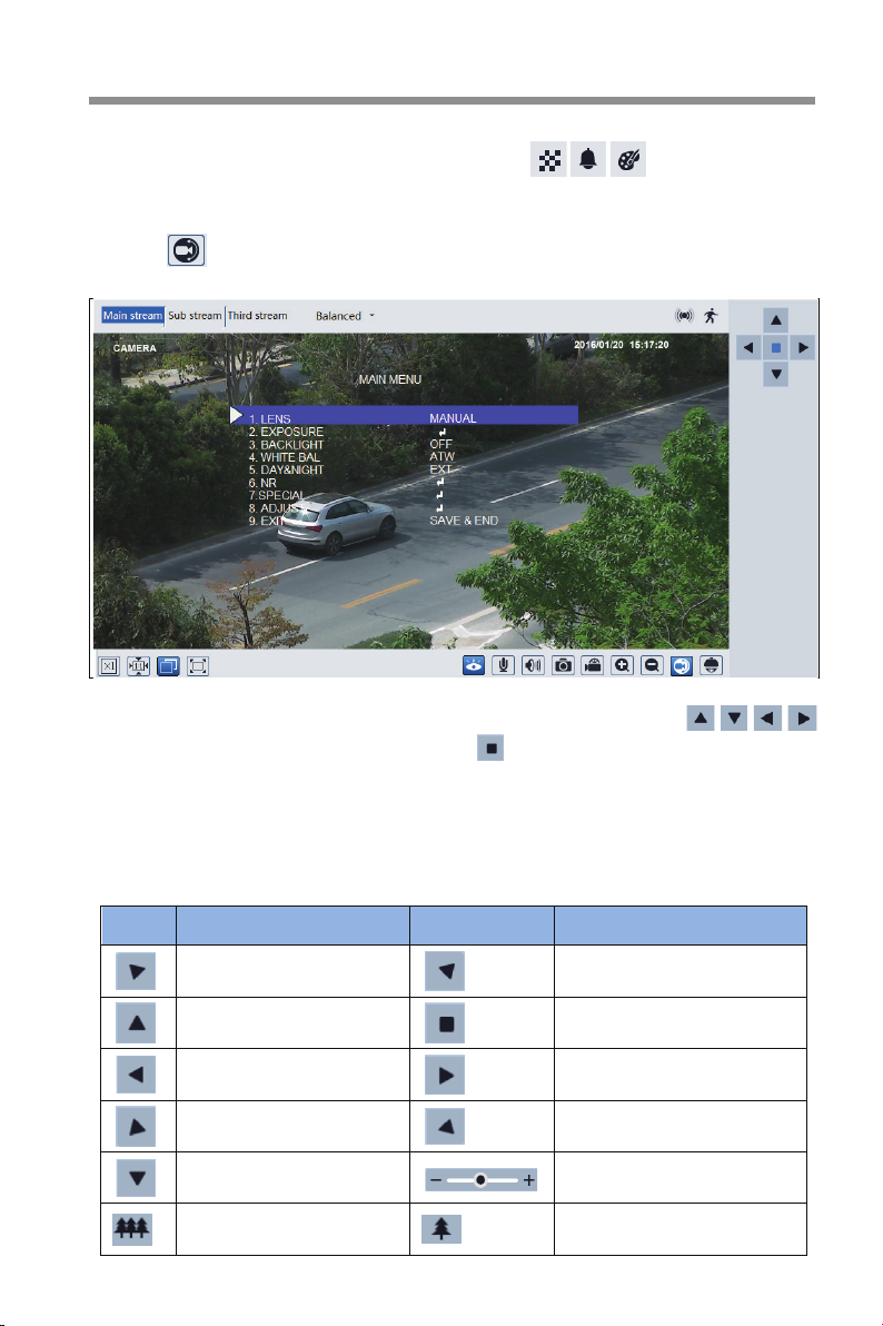
You can call the main menu of the analog camera connected to the DVS by
clicking (
) CoC button as shown below, if the camera allows CoC function
Different cameras may have different menus. You can click
direction keys to select the menu and click button to confirm.
Click PTZ extended button to unfold PTZ control panel. In remote preview interface,
you can view the image from every direction by controlling PTZ panel. The
descriptions of the control panel are as follows:
Icon Description Icon Description
Click
diagonally up-left
upwards.
towards left
diagonally down-left
downwards.
image.
diagonally up-right.
Click to stop rotating the dome.
Click to rotate the dome towards
right.
diagonally down-right.
rotating speed of the dome.
Click it to zoom in the live image.
Page 13

12
Focus -
Focus +
VT-IPS-HDA2
Iris -
Auto scan
Light
Group scan
Iris +
Wiper
Radom scan
Preset
Select preset and click to call the preset. Select and set the preset and then
click to save the position of the preset. Select the set preset and click to
delete it.
Page 14
VT-IPS-HDA2
13
4 Remote Configuration
4.1 System Configuration
The “System” configuration includes four submenus: Basic Information, Date and
Time, Local Config and Storage.
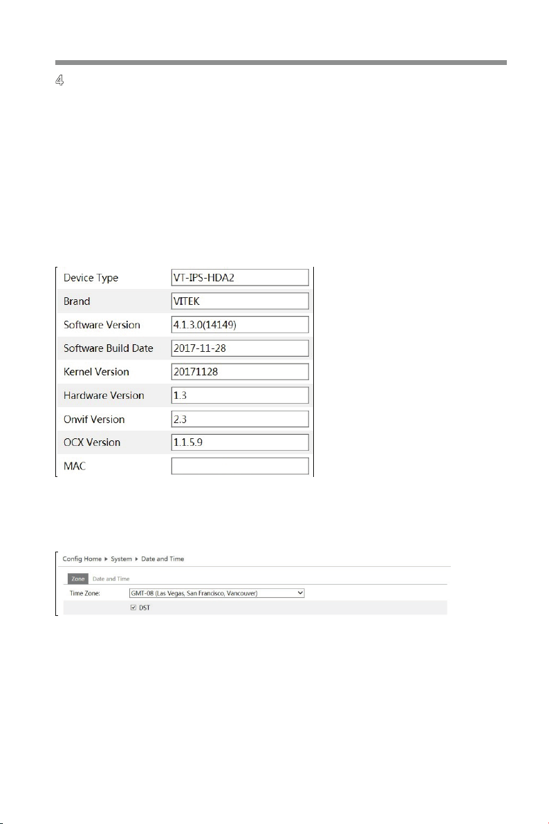
4.1.1 Basic Information
In the “Basic Information” interface, you can check relative information of the
device.
4.1.2 Date and Time
Go to ConfigàSystemàDate and Time. Please refer to the following interface.
You can select the time zone and DST as required.
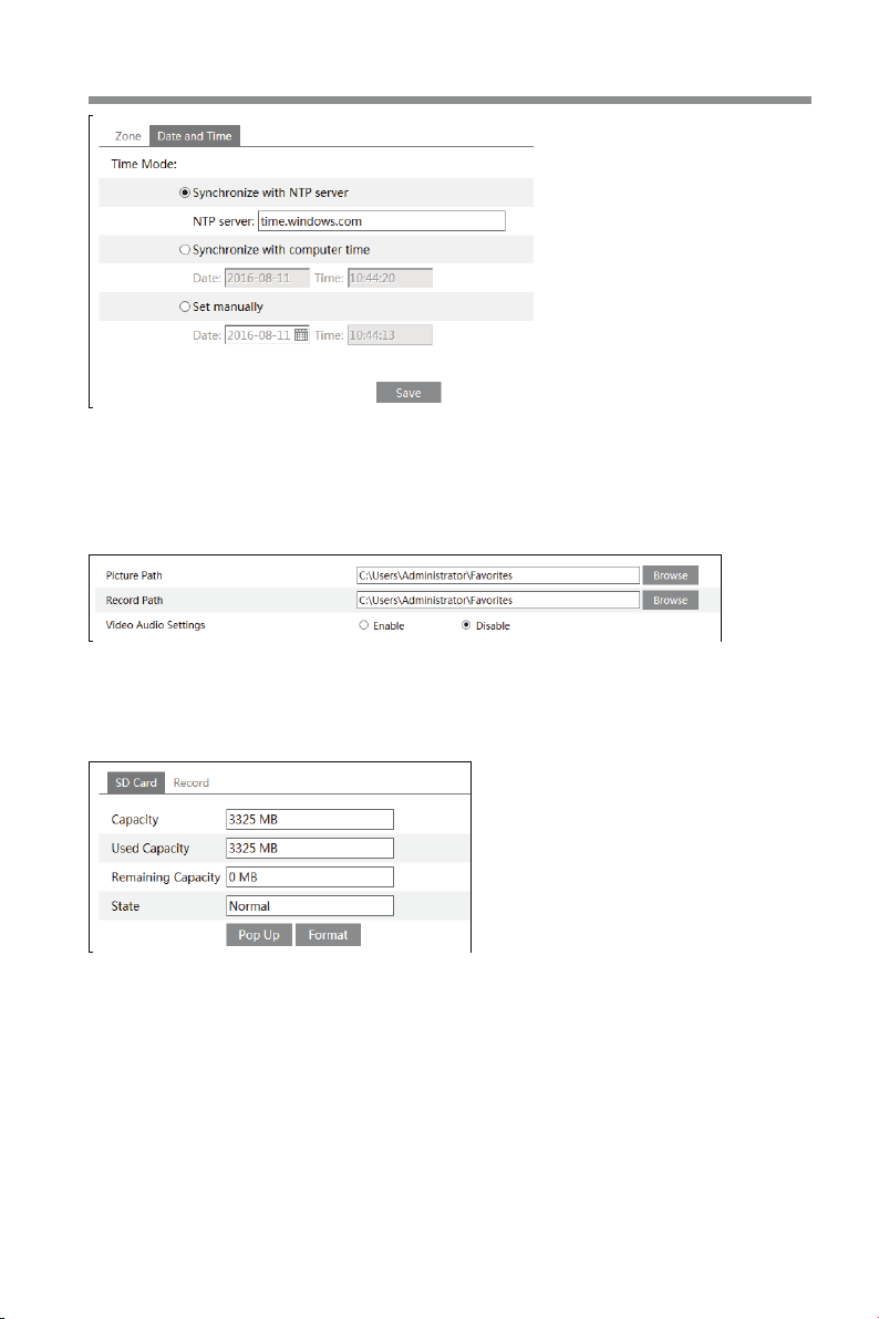
Click “Date and Time” tab to set the time mode.
Page 15
14
VT-IPS-HDA2
4.1.3 Local Config
Go to ConfigàSystemàLocal Config. You can set the storage path of the
captured pictures and video recording. You can also enable or disable the audio.
4.1.4 Storage
Go to ConfigàSystemàStorage to go to the interface as shown below.
The first time you use a SD card, you should click the “Format” button to format the
SD card.
Click “Pop Up” button to stop writing data to SD card. Then the SD card can be
ejected safely.
SD card function should be coordinated with alarm. When an alarm is triggered,
the system will automatically capture picture and save the picture or recording onto
the SD card. (See Chapter 4.5 Alarm Configuration or Chapter 4.6 Event
Configuration for details).
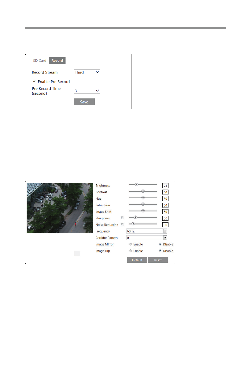
Go to ConfigàSystemàStorageàRecord to go to the interface as shown below.
You can set the SD card record stream. Set the pre record time if you enable pre
Page 16
VT-IPS-HDA2
15
record. Click “Save” button to save the settings.
Pre Record Time: Set the time to record before the actual recording begins.
4.2 Image Configuration
Image Configuration includes Display, Video/Audio, OSD, Video Mask and ROI
Config.
4.2.1 Display Configuration
Go to ImageàDisplay interface as shown below. You may set and adjust the
picture’s brightness, contrast, hue and saturation, etc.
Brightness: Set the brightness level of the camera’s image.
Contrast: Set the color difference between the brightest and darkest parts.
Hue: Set the total color degree of the image.
Saturation: Set the degree of color purity. The purer the color is, the brighter the
image is.
Image Shift: If there is black edge in the live image, you can change the value to
eliminate the back edge.
Sharpness: Set the resolution level of the image plane and the sharpness level of
the image edge.
Noise Reduction: Decrease the noise and make the image more thorough.
Page 17

16
VT-IPS-HDA2
Increasing the value will make the noise reduction effect better but it will reduce the
image resolution.
Frequency: 50Hz and 60Hz can be set.
Corridor Pattern: You can change the direction of the video image by using this
function. 0, 90, 180 and 270 are available. The default value is 0. The video
resolution needs to be 1920 x1080 or under if you use this function.
Image Mirror: Reverse the current video image right and left.
Image Flip: Turn the current video image upside down.
4.2.2 Video / Audio Configuration
Go to ImageàVideo / Audio interface as shown below. In this interface, you can
set the resolution, frame rate, bitrate type, and video quality etc. subject to the
actual network condition.
Click “Audio” tab to go to the interface as shown below.
Three video streams can be adjusted.
Resolution: The higher the resolution is, the clearer the image is.
Frame rate: The higher the frame rate is, the more fluid the video is. However,
more storage will be taken up.
Bitrate type: Including CBR and VBR. CBR means that no matter how much the
video changes the compression bitrate keeps constant. This will not only facilitate
the image quality better in a constant bitrate but also helps to calculate the
capacity of the recording. VBR means that the compression bitrate will adjust
according to the changes in the video resources. This will help to optimize the
network bandwidth.
Page 18

VT-IPS-HDA2
17
Bitrate: Please choose according to the actual network situation.
Video Quality: When VBR is selected, you need to choose image quality. The
higher the image quality you choose, the more bitrate will be required.
I Frame interval: It is recommended to use the default value. If the value is
too high, the read speed of the group of pictures will be slow resulting in the quality
loss of the video.
Video Compression: H264 and H265 are options. Higher quality of image
can be transferred under limited network bandwidth by using H265 video encoding;
however, a higher quality of hardware is required.
Profile: Baseline, main/high profiles are options. Baseline profile is mainly
used in interactive application with low complexity and delay. Main/high profile is
mainly used for higher coding requirement.
Send Snapshot: Please select according to the actual application.
Video encode slice split: If enabled, you may get more fluid video even
though using a low-performance PC.
Watermark: Enable it and input the content. Then you can check the
watermark when playing back the local recording in the search interface to see if it
has been tampered with.
Audio Encoding: G711A and G711U are selectable.
Audio Type: MIC and LIN are selectable.
4.2.3 OSD Configuration
Go to ImageàOSD interface as shown below.
You can set time stamp, device name and OSD content here. After enabling the
corresponding display and entering the content, drag them to change their position.
Then click “Save” button to save the settings.
Page 19

18
VT-IPS-HDA2
4.2.4 Video Mask
Go to ImageàVideo Mask interface as shown below. You can set 4 masked areas
at most.
To set up video mask:
1. Enable video mask.
2. Click “Draw Area” button and then drag the mouse to draw the mask area.
3. Click “Save” button to save the settings.
4. Return to the live screen to see the following picture.
Clear the video mask:
Go to video mask interface and then click “Clear” button to delete the current
masked area.
4.2.5 ROI Configuration
Go to ImageàROI Config interface as shown below.
Page 20

VT-IPS-HDA2
19
1. Check “Enable” and then click “Draw Area” button.
2. Drag the mouse to set the ROI area.
3. Set the level.
4. Click “Save” button to save the settings.
Now, you will see the selected ROI area is clearer than other areas especially in
low bitrate condition.
4.3 PTZ Configuration
Go to PTZàProtocol interface as shown below.
Set the protocol, address and baud rate according to the PTZ.
Page 21

20
VT-IPS-HDA2
4.4 Alarm Configuration
Alarm configuration includes four submenus: Motion Detection, Alarm In, Alarm
Out and Alarm Server.
4.4.1 Motion Detection
Go to AlarmàMotion Detection to set motion detection alarm.
1. Check “Enable Alarm” check box to activate motion based alarm, choose alarm
holding time and set alarm trigger options.
Alarm Out: If selected, this would trigger the external relay output on detecting a
motion based alarm.
Trigger Snap: If selected, the system will snap images on an alarm and save the
images in SD card.
Trigger SD Recording: If selected, the recording will be triggered and saved in
SD card on an alarm.
Trigger Email: If “Trigger Email” and “Attach Picture” checkbox are checked
(email address should be set first in the Email configuration interface), the
captured pictures and triggered event will be sent to those addresses.
Trigger FTP: If “Trigger FTP” and “Attach Picture” checkbox are checked, the
captured pictures will be sent to the FTP server address. Please refer to FTP
configuration chapter for more details.
2. Set motion detection area and sensitivity. Click “Area and Sensitivity” tab to go
to the interface as shown below.
Page 22

VT-IPS-HDA2
21
Move the “Sensitivity” scroll bar to set the sensitivity.
Select “Add” and click “Draw” button and drag mouse to select the motion
detection area; Select “Erase” and drag the mouse to clear motion detection area.
After that, click “Save” to save the settings.
3. Set the schedule of the motion detection. Click “Schedule” tab to go to the
interface as shown below.
Week schedule
Page 23

22
VT-IPS-HDA2
Set the alarm time from Sunday thru Saturday for alarm everyday in one week.
The lengthwise means one day of a week; the rank means 24 hours of a day.
Green means selected area. Blank means unselected area.
“Add”: Add the schedule for a special day.
“Erase”: Delete holiday schedule.
Holiday schedule
Set alarm time for a special day, such as holiday.
Set a date in the “Date” box, click “Add” button to add that date to the list box on
the right side and then drag the scroll bar to set the schedule for that day.
Select a date in the list box on the right side, and click “Delete” to remove the
schedule on that day.
Click “Save” button to save the settings.
Note: Holiday schedule is prior to Week schedule.
4.4.2 Alarm In
To set sensor alarm (alarm in):
Go to ConfigàAlarmàAlarm In interface as shown below.
1. Enable alarm and set the alarm type, alarm holding time and sensor name.
2. Set alarm trigger options. The setting steps are the same with that of motion
detection. Please refer to motion detection chapter for details.
3. Click “Save” button to save the settings.
4. Set the schedule of the sensor alarm. The setting steps of the schedule are the
Page 24

VT-IPS-HDA2
23
same with that of motion detection. Please refer to motion detection chapter for
details.
4.4.3 Alarm Out
Go to ConfigàAlarmàAlarm Out interface as shown below:
Select alarm holding time at the “Alarm Holding Time” pull down list box.
Click “On” to trigger alarm out. Click “off” to stop alarm out.
Click “Save” button to save the settings.
4.4.4 Alarm Server
Go to AlarmàAlarm Server interface as shown below.
You may input the alarm server address and port. When the alarm happens, the
camera will automatically transfer the alarm event to the alarm server. If the alarm
server is not used, there is no need for you to configure here.
4.5 Event Configuration (Optional)
(Only some customized version may support the following functions).
For enabling the following alarm functions, please meet the following installation
requirement.
l Cameras should be installed in settled places, lest too much shaking affects
the accuracy of detection.
l Avoid the reflective surfaces (like shiny floors, mirrors, glass, lake surfaces
and so on).
l Avoid narrow or too much shadowing monitoring places.
l Avoid such monitoring scenario - the object color is similar to the background
color.
l The monitoring images shouldn’t have large changes after enabling the smart
alarms, or it will result in frequency alarm triggers (for example, the function of
auto focus or automatic white balance is automatically enabled).
At any time of day or night, please make sure the image of cameras is clear and
Page 25

24
VT-IPS-HDA2
with adequate and even light, avoiding overexposure or too dark on both sides.
4.5.1 Exception
This function can detect the change of surveillance environment affected by the
external factors and the blur and cast of the surveillance images and some certain
actions can be taken when the alarm is triggered.
To set exception detection:
Go to ConfigàEventàException interface as shown below.
1. Enable the relevant detection as required.
Scene Change Detection: The relevant alarms will be triggered if the scene of the
monitor video has changed.
Video Blur Detection: The relevant alarms will be triggered if the monitor video is
blurry.
Video Cast Detection: The relevant alarms will be triggered if color cast happens
to the monitor video.
2. Set the alarm holding time and alarm trigger options. The setting steps are the
same with that of motion detection. Please refer to motion detection chapter for
details.
3. Click “Save” button to save the settings.
4. Set the sensitivity of the exception detection. Click “Sensitivity” tab to go to the
interface as shown below.
Page 26

VT-IPS-HDA2
25
Drag the slider to set the sensitivity value or directly input the sensitivity value in
the textbox. Click “Save” button to save the settings.
The sensitivity value of Scene Change Detection: The higher the value is, the
more sensitive the system responds to the amplitude of the scene change.
The sensitivity value of Video Blur Detection: The higher the value is, the more
sensitive the system responds to the defocus of the device image. You should just
the value according to the real situation.
The sensitivity value of Video Cast Detection: The higher the value is, the more
sensitive the system responds to the color cast of the device image. You should
also consider other factors.
※ The requirements of camera and ambient requirements
1. Auto-focusing function should not been enabled for exception detection.
2. Try not to enable exception detection when light changes greatly in the scene.
3. Detect the exception of the image in the whole surveillance scene, including six
kinds of exception events- low light, excessive brightness, low definition, color cast,
interference and scene change.
4. Please contact us for more detailed application scenarios.
4.5.2 Line Crossing
Line Crossing: The relevant alarms will be triggered if someone or something
crosses the pre-defined alarm lines. It can replace the electronic fence, warning
line of flood prevention, etc.
Go to ConfigàEventàLine Crossing interface as shown below.
Page 27

26
VT-IPS-HDA2
1. Enable line crossing alarm and set the alarm holding time.
2. Set alarm trigger options. The setting steps are the same with that of motion
detection. Please refer to motion detection chapter for details.
3. Click “Save” button to save the settings.
4. Set area and sensitivity of the line crossing alarm. Click “Area and Sensitivity”
tab to go to the interface as shown below.
Set the cordon number and direction. You can add 4 cordons at most.
Direction:A<->B, A->B and A<-B optional. It is the crossing direction of the
intruder who crosses over the alarm line.
A<->B: The alarm will be triggered when the intruder crosses over the alarm line
from B to A or from A to B.
A->B: The alarm will be triggered when the intruder crosses over the alarm line
Page 28

VT-IPS-HDA2
27
There are so many
trees near the road
from A to B.
A<-B: The alarm will be triggered when the intruder crosses over the alarm line
from B to A.
Click “Draw” button and then drag the mouse to draw a cordon in the image on the
left side. Click “Stop” button to stop drawing. Click “Clear” button to delete the
cordons. Click “Save” button to save the settings.
5. Set the schedule of the line crossing alarm. The setting steps of the schedule
are the same with that of motion detection. Please refer to motion detection
chapter for details.
※ The installation requirements of camera and ambient requirements
1. Auto-focusing function should not been enabled for line crossing detection. If
enabled, the video image will change so greatly that the algorithm will stop working
temporarily.
2. Avoid the scenes with many trees or the scenes with various light changes (like
many flashing headlights). The ambient brightness of the scenes shouldn’t be too
low, because dimly lighted scenes will decrease the accuracy of the alarm.
3. Cameras should be mounted at a place of 2.8 meters height or above.
4. The mounting view angle of the camera tries to keep about 45°.
5. The detected objects accounting for the proportion in the whole image should
not be less than 1% and the largest sizes of the detected objects accounting for the
proportion in the whole image should not be more than 1/8.
6. Make sure cameras can view objects for at least 2 seconds in the detected area
for accurate detection.
7. Adequate light and clear scenery are very important to line crossing detection.
8. Please contact us for more detailed application scenarios.
Here we take some improper application scenarios for instance.
and cars running on
the road, which make
the scene too complex
to detect the crossing
objects.
Page 29

28
above mentioned
environment is too
detect the
VT-IPS-HDA2
The ground is covered
with vegetation; at the
right of the fence is a
gym where people pass
by frequently. The
complex to
crossing objects.
4.5.3 Intrusion
Intrusion: The relevant alarms will be triggered if someone or something intrudes
into the alarm areas or moves in the pre-defined alarm areas. This function can be
applicable to important supervision places, danger areas and prohibited areas, like
military administrative zones, house breaking, scenic high danger areas, no man’s
areas, etc.
Go to ConfigàEventàIntrusion interface as shown below.
1. Enable region intrusion detection alarm and set the alarm holding time.
2. Set alarm trigger options. The setting steps are the same with that of motion
detection. Please refer to motion detection chapter for details.
3. Click “Save” button to save the settings.
4. Set the alarm area of the intrusion detection. Click “Area” tab to go to the
interface as shown below.
Page 30

VT-IPS-HDA2
29
Set the alarm area number on the right side. You can add 4 alarm areas at most.
Click “Draw Area” button and then click around the area where you want to set as
the alarm area in the image on the left side (the alarm area should be a closed
area). Click “Stop Draw” button to stop drawing. Click “Clear” button to delete the
alarm area. Click “Save” button to save the settings.
5. Set the schedule of the intrusion detection. The setting steps of the schedule are
the same with that of motion detection. Please refer to motion detection chapter for
details.
※ The installation requirements of camera and ambient requirements
1. Auto-focusing function should not been enabled for line crossing detection. If
enabled, the video image will change so greatly that the algorithm will stop working
temporarily.
2. Avoid the scenes with many trees or the scenes with various light changes (like
many flashing headlights). The ambient brightness of the scenes shouldn’t be too
low, because dimly lighted scenes will decrease the accuracy of the alarm.
3. Cameras should be mounted at a place of 2.8 meters height or above.
4. The mounting view angle of the camera tries to keep about 45°.
5. The detected objects accounting for the proportion in the whole image should
not be less than 1% and the largest sizes of the detected objects accounting for the
proportion in the whole image should not be more than 1/8.
6. Make sure cameras can view objects for at least 2 seconds in the detected area
for accurate detection.
7. Adequate light and clear scenery are very important to line crossing detection.
8. Please contact us for more detailed application scenarios.
Here we take some improper application scenarios for instance.
Page 31

30
s angle of
depression is not wide
above mentioned
is too
to detect the
s angle of
depression is not wide
at night lead to light
mproper for intrusion
VT-IPS-HDA2
The camera’
enough; there are so many
trees in the scene. The
environment
complex
intrusion.
The camera’
enough; the street lamps
interference; the swaying
trees in a windy day lead
to random interference.
All the above mentioned
factors make the scene
i
detection.
4.6 Network Configuration
4.6.1 TCP/IP
Go to ConfigàNetworkàTCP/IP interface as shown below. There are two ways for
network connection.
IP address (take IPv4 for example)-There are two options for IP setup: obtain an
IP address automatically by DHCP protocol and use the following IP address.
Page 32

VT-IPS-HDA2
31
Please choose one of the options for your requirements.
PPPoE-Click “PPPoE Config” tab to go to the interface as shown below. Enable
PPPoE and then enter the user name and password from your ISP.
You can choose either way for the network connection. If you use PPPoE to
connect to the internet, you will get a dynamic WAN IP address. This IP address
will change frequently. You may use the function of IP change notification.
Click “IP Change Notification Config” to go to the interface as shown below.
Trigger Email: when the IP address of the device is changed, a new IP address
will be sent to the appointed mailbox automatically
Trigger FTP: when the IP address of the device is changed, a new IP address will
be sent to the FTP server.
4.6.2 Port
Go to ConfigàNetworkàPort interface as shown below. HTTP port, Data port and
RTSP port can be set here.
HTTP Port: The default HTTP port is 80. It can be changed to any port which is not
occupied.
Page 33

32
device ID. Please check it in the ECMS/NVMS.
VT-IPS-HDA2
Data Port: The default data port is 9008. Please change it as required.
RTSP Port: The default port is 554. Please change it as required.
4.6.3 Server Configuration
This function is mainly used for connecting network Video Management System.
1. Check “Enable”.
2. Check the IP address and port of the transfer media server in the ECMS/NVMS.
Then enable the auto report in the ECMS/NVMS when adding a new device. Next,
input the remaining information of the device in the ECMS/NVMS. After that, the
system will auto allot a
3. Input the above-mentioned server address, server port and device ID in the
responding boxes. Click “Save” button to save the settings.
4.6.4 DDNS
If your camera is set to use PPPoE as its default network connection, DDNS
should be set for network access. Before you set the DDNS, please make sure you
have registered a domain name on the DDNS server.
1. Go to ConfigàNetworkà DDNS.
2. Apply for a domain name. Take www.dvrdyndns.com for example.
Page 34

VT-IPS-HDA2
33
Input www.dvrdydns.com in the IE address bar to visit its website. Then click
“Registration” button.
Create domain name.
After you successfully request your domain name, you will see your domain in the
list.
3. Input the username, password, domain you apply for in the DDNS configuration
interface.
4. Click “Save” button to save the settings.
Page 35

34
VT-IPS-HDA2
4.6.5 SNMP
To get server status, parameters and alarm information and remotely manage the
server, you can set the SNMP function. Before using the SNMP, please download
the SNMP software and set the parameters of the SNMP, such as SNMP port, trap
address.
1. Go to ConfigàNetworkàSNMP.
2. Check the corresponding version checkbox (Enable SNMPv1, Enable SNMPv2,
Enable SNMPv3) according to the version of the SNMP software you download.
3. Set the “Read SNMP Community”, “Write SNMP Community”, “Trap Address”,
“Trap Port” and so on. Please make sure the settings are the same as that of your
SNMP software.
Note: Please use a different version in accordance with the security level you
required. The higher the version is, the higher the level of the security is.
Page 36

VT-IPS-HDA2
35
4.6.6 RTSP
Go to ConfigàNetworkàRTSP.
Page 37

36
VT-IPS-HDA2
1. Select “Enable”.
2. RTSP Port: Access port of the streaming media. The default number is 554.
3. RTSP Address: The RTSP address you need to input in the media player.
4. Check “Allow anonymous login…”.
4.6.7 UPNP
If you enable this function, you can quickly access the camera via LAN and you
don’t need to configure the port mapping when the camera is connected to the
WAN via the router.
Go to ConfigàNetworkàUPnP. Enable UPNP and then input UPnP name.
After you enable it and set the UPnP name, you will see the UPnP name by
clicking “Network” on the desktop of your computer which is in the same local area
network. Then double click this name to access the camera quickly.
4.6.8 Email
If you need to trigger Email when an alarm happens or IP address is changed,
please set the Email here first.
Go to ConfigàNetwork àEmail.
Page 38

VT-IPS-HDA2
37
Sender Address: sender’s e-mail address.
User name and password: sender’s user name and password.
Server Address: The SMTP IP address or host name.
Select the secure connection type at the “Secure Connection” pull-down list
according to actual needs.
SMTP Port: The SMTP port.
Send Interval(S): Set it as needed.
Click “Test” button to test the effectiveness of the account.
Recipient Address: receiver’s e-mail address.
4.6.9 FTP
After you set the FTP server, the captured pictures on an alarm will be uploaded to
the FTP server.
Go to ConfigàNetwork àFTP.
Page 39

38
To Add FTP:
Server Name: The name of the FTP.
Server Address: The IP address or domain name of the FTP.
Upload Path: The path of uploading the files.
Port: The port of the FTP.
Use Name and Password: You should use them to login the FTP.
4.7 Security Configuration
4.7.1 User Configuration
Go to ConfigàSecurityàUser interface as shown below.
VT-IPS-HDA2
Add user:
1. Click “Add” button to pop up the following textbox.
Page 40

VT-IPS-HDA2
39
2. Input user name in “User Name” textbox.
3. Input letters or numbers in “Password” and “Confirm Password” textbox.
4. Choose the use type.
5. Input the MAC address of the PC in “Bind MAC” textbox.
After binding MAC address to the IP-CAM, you can access the device on this PC
only. If the MAC address was “00:00:00:00:00:00” which means it can be
connected to any computers.
6. Click “OK” button and then the new added user will display in the user list.
Modify user:
1. Select the user you need to modify password and physical address in the user
configuration list box.
2. The “Edit user” dialog box pops up by clicking “Modify” button.
3. Input old password of this user in the “Old Password” text box.
4. Input new password in the “New password” and “Confirm Password” text box.
5. Input computer’s MAC address as required.
6. Click “OK” button to save the settings.
Delete user:
Page 41

40
VT-IPS-HDA2
1. Select the user you want to delete in the user configuration list box.
2. Click “Delete” button to delete the user.
Note: The default super administrator cannot be deleted.
4.7.2 Online User
Go to ConfigàSecurityàOnline User. You can view the user who is viewing the
live video.
4.7.3 Block and Allow Lists
Go to ConfigàSecurityàBlock and Allow Lists interface as shown below.
Setting steps are as follows:
Check “Enable IP address filtering” check box.
Select “Block the following IP address”, input IP address in the IP address list box
and click “Add” button. The operation step of “Allow the following IP address” and
MAC address filter settings are the same with “Block the following IP address”.
After you set the IP address or MAC address, the system will block or allow the
user using the added IP address or MAC address to access the camera.
4.8 Maintenance Configuration
4.8.1 Backup and Restore
Go to ConfigàMaintenanceàBackup & Restore.
Page 42

VT-IPS-HDA2
41
l Import & Export Settings
You can import or export the setting information from PC or to device.
1. Click “Browse” to select save path for import or export information on PC.
2. Click “Import Setting” or “Export Setting” button.
l Default Settings
Click “Load Default” button to restore all system settings to default status.
4.8.2 Reboot
Go to ConfigàMaintenanceàReboot.
Click “Reboot” button to reboot the device.
Timed Reboot Setting:
Enable “Time Settings”, set the date and time and then click “Save” button to save
the settings.
4.8.3 Upgrade
Go to ConfigàMaintenanceàUpgrade. In this interface, you can upgrade the
system.
1. Click “Browse” button to select the save path of the upgrade file
2. Click “Upgrade” button to start upgrading the application program.
3. The device will restart automatically
4. After you successfully update the software, click “OK” button to close IE and
Page 43

42
VT-IPS-HDA2
then re-open IE to connect IP-Cam.
Caution! You can’t disconnect to PC or close the IP-CAM during upgrade.
4.8.4 Operation Log
To query and export log:
1. Go to ConfigàMaintenanceàOperation Log.
2. Select the main type, sub type, start and end time.
3. Click “Search” to view the operation log.
4. Click “Export” to export the operation log.
Page 44

VT-IPS-HDA2
43
and click this button to
close this picture.
Close all: Click this
pictures viewing.
Save: Click this button
to select the save path
for saving the current
picture.
on PC for
5 Search
5.1 Photo Search
Click SearchàPhoto to go to the interface as shown below. You can search the
images saved in the SD card.
1. Set time: Select date and choose the start and end time in the top left corner.
2. Check events.
3. Click “Search” button to search the photos.
4. Click a file name in the list to view captured photos as shown above.
The descriptions of the buttons are shown as follows.
Icon Description Icon Description
Close: Select a picture
of the picture on the PC
button to close all
Save all: Click this button
to select the save path of
the pictures
saving all pictures.
Page 45

44
Icon Description Icon Description
this button.
Actual size: Click this
button to display the
actual size of the picture.
Zoom in: Click this
button to amplify the
picture.
Zoom out: Click this
button to zoom out the
picture.
: Click
this button to play the
picture in slide show
mode.
Fit size: The picture will
fit on screen by clicking
VT-IPS-HDA2
Slide show play
Play speed: Play speed of the slide show.
Stop: Click this button to
stop slide show.
5.2 Video Search
5.2.1 Local Video Search
Click SearchàVideoàLocal Video to go to the interface as shown below. You can
play the local video record. Before playing, please set the storage path of the video
record in the local configuration interface and make sure there are record files.
Choose the date and the start time and end time and then click “Search” button to
search the record files. Double click the record file to play the record. The
descriptions of the buttons on the playback interface are as follows.
Icon Description Icon Description
Page 46

VT-IPS-HDA2
45
previous record
Click it to play the
next record.
watermark.
Click it to enable /
disable audio; drag
the slider to adjust
the volume after
enabling audio.
it to display full
screen. Double
click to exit full
screen.
Icon Description Icon Description
Play button
Stop button
Speed up
Pause button
Speed down
Click it to play the
Open/close
Full screen. Click
5.2.2 SD Card Video Search
Click SearchàVideoàSD Card Recording to go to the interface as shown below.
You can search the record saved in the SD card.
Before you search the SD record, you should trigger the SD recording in motion
detection alarm or alarm input alarm (see Motion Detection Trigger or Alarm Input
Trigger for detail information).
Set the date and the start and end time, select the record type and then click
“Search” button to search the record. Double click the searched file name to play
the record.
Please refer to Local Video Search for the descriptions of the buttons on the
playback interface.
Click button to download the record saved in the SD card.
Page 47

46
VT-IPS-HDA2
6 Appendix
Appendix 1 Q & A
Q: How to find my password if I forget it?
A: Reset the device to the default factory settings.
Default IP: 192.168.226.201; User name: admin; Password: 123456
Q: Fail to connect devices through IE browser, why?
A: Network is not well connected. Check the connection and make sure it is
connected well.
B: IP is not available. Reset the valid IP.
C: Web port number has been revised: contact administrator to get the correct port
number.
D: Exclude the above reasons. Recover default setting by IP-Tool.
Q: IP tool cannot search devices, why?
A: It may be caused by the anti-virus software in your computer. Please exit it and
try to search device again.
Q: IE cannot download ActiveX control. How can I do?
A: IE browser blocks ActiveX. Please do setup as below.
① Open IE browser and then click Tools-----Internet Options….
② Select Security------Custom Level….
③ Enable all the sub options under “ActiveX controls and plug-ins”.
④ Then click OK to finish setup.
b. Other plug-ins or anti-virus blocks ActiveX. Please uninstall or close them.
Page 48

47
VT-IPS-HDA2
Q:No sound can be heard, why?
A: Audio input device is not connected. Please connect and try again.
B: Audio function is not enabled at the corresponding channel. Please enable this
function.
Page 49

48
Appendix 2: Specifications
Transcendent 4 MegaPixel H.265 HD
Video Server with Intelligent Analytics
VT-IPS-HDA2
5.51”
1.14”
Detailed Specifications
HD Analog Video Input
Audio Input
Video Compression
H. 264 Compression Standard
Bit Rate Type
Quality
Bit Rate
Resolution
Multi-streams
Audio Compression
Image Settings
ROI
Network
Audio
Storage Card
RS485
Alarm Input
Alarm Output
Local Output
Remote Monitoring
Online Connection
Network Protocol
Interface Protocol
Image Snap
Intelligent Analytics
Ingress Protection
Power Supply
Power Output
Power Consumption
Installation
Operating Environment
Weight ( net )
Dimensions (W x H x D)
VT-IPS-HDA2
1 CH, BNC Supporting up to 4MP AHD / TVI / CVI / CVBS
1 CH: 3.5 mm interface, share with MIC IN interface
H.264, H.265, MJPEG
Baseline Profile / Main Profile / High Profile
Five levels under VBR; Freely adjustable under CBR
4MP (2560×1440), 3MP (2304×1296) / (2048×1536), 1080P (1920×1080), 960P (1280×960), 720P (1280×720), D1, CIF, 480×240
4MP / 3MP / 1080P / 960P / 720P / D1 / CIF / D1 / CIF (All at 1~30fps)
ROI, Saturation, Brightness, Chroma, Contrast, Wide Dynamic, Sharpen, NR, etc.
Supports simultaneous monitoring for up to 10 users; Support multi-stream real time transmission
TCP / IP, UDP, DHCP, NTP, RTSP, PPPoE, DDNS, SMTP, FTP
Scene change, Video Blur, Video Cast, Line Cross, and Intrusion
VBR / CBR
32Kbps ~ 16Mbps
G711A/U, ADPCM, G.726
3 Regions of Interest (ROI)
RJ45
MIC IN × 1, SPK OUT × 1
Up to 128GB
Yes - For PTZ Control (Pelco-P & Pelco-D)
1 CH alarm input
1 CH alarm output
1 CH BNC output
IE browsing, CMS remote control
ONVIF, GB-T / 28181-2011
JPEG encoding, image quality adjustable
TVS6000V lightning protection, surge protection
PoE / DC12V
Max 12V@0.5A
< 4W
Wall mount
-4~131F (-20~55c) / 10% ~ 90% RH
7.76 oz. / 220g
5.51” x 1.14” x 2.93” (140x29x74.3mm)
0.66”
0.66”
2.93”
1.56”
4.80”
4.02”
Page 50

Page 51

LIMITED PRODUCT WARRANTY
VITEK products carry a three (3) year limited warranty. VITEK
warrants to the purchaser that products manufactured by VITEK
are free of any rightful claim of infringement or the like, and when
used in the manner intended, will be free of defects in materials
and workmanship for a period of three (3) years, or as otherwise
stated above, from the date of purchase by the end user. This
warranty is nontransferable and extends only to the original buyer
or end user customer of a VITEK Authorized Reseller.
The product must have been used only for its intended purpose,
and not been subjected to damage by misuse, willful or accidental
damage, caused by excessive voltage or lightning.
The product must not have been tampered with in any way or the
guarantee will be considered null and void.
This guarantee does not affect your statutory rights.
Contact your local VITEK Reseller should servicing become
necessary.
VITEK makes no warranty or guarantee whatsoever with
respect to products sold or purchased through unauthorized
sales channels. Warranty support is available only if product is
purchased through a VITEK Authorized Reseller.
Page 52

28492 CONSTELLATION ROAD VALENCIA, CA 91355
WWW.VITEKCCTV.COM
Version 1.0
January 2018
 Loading...