

Page 1
VITEK
VT-HDOC Series
4 & 8 Channel Real-Time HD-SDI
Digital Video Recorders
• 4 or 8 HD-SDI Inputs with Full 1080p Camera Support
• Simple plug and play, point-to-point connection from camera to DVR
• VT-HDOC8: 240fps Live Display Speed at 720p/1080p & 240fps Recording &
Playback at 720p / 120fps at 1080p
• VT-HDOC4: 120fps Live Display Speed at 720p/1080p & 120fps Recording &
Playback at 720p / 60fps at 1080p
• HDMI, VGA, and BNC Outputs
• 2 Internal SATA2/SATA3 HDD Slots supporting up to 8TB (2 x 4TB HDD) using
Advanced HDD Format
• Optional External SATA Port (eSATA)
• Dual Recording Mode (Individually Selectable per Camera)
• Add 4 Analog SD Cameras (per HD input) with optional external box (VT-QHD4)
• Remote Viewing via local Software, Web Browser, and Mobile Phones (iOS/Android)
• Pentaplex Operation (Live, Playback, Recording, Backup, Network)
• Alarm In/Out
• 4 Channel Audio In
• 16 x 12 Motion Detection Grid
• Thumbnail Search
• Linear digital zoom for live and playback
• Embedded Web Server for Remote Setup & Viewing
• Up to 8 Simultaneous Network/Remote Connections
• 64 Camera Remote Viewing
Page 2

VT-HDOC Series
1
TABLE OF CONTENTS
1. BEFORE INSTALLING ............................................................................................................................... 3
1.1 UPDATING SYSTEM F/W .............................................................................................................. 3
1.1.1 WITH A USB THUMB DRIVE .............................................................................................. 3
1.1.2 UPDATING FROM THE WEB MENU ................................................................................. 5
1.2 FRONT AND REAR ........................................................................................................................ 9
2. GETTING STARTED ................................................................................................................................ 11
2.1 CONNECT AND SWITCH ON ...................................................................................................... 11
3. TOOL BAR ................................................................................................................................................ 13
3.1 STATUS DISPLAY ........................................................................................................................ 13
3.2 LOG OFF ...................................................................................................................................... 14
3.3 MAIN MENU POP-UP ................................................................................................................... 14
3.4 ARCHIVE MENU POP-UP ............................................................................................................ 14
3.5 SEARCH MENU POP-UP ............................................................................................................. 15
3.6 DISPLAY POP-UP ........................................................................................................................ 16
3.7 PTZ MODE ................................................................................................................................... 16
3.8 DIGITAL ZOOM............................................................................................................................. 17
3.9 LOG LIST ...................................................................................................................................... 18
3.10 PANIC RECORD ........................................................................................................................... 20
4. SEARCH & PLAYBACK ............................................................................................................................ 21
4.1 TIME / CALENDAR SEARCH ................................ ................................ ....................................... 21
4.2 PANORAMA SEARCH (Thumbnail search) .................................................................................. 23
4.3 EVENT SEARCH .......................................................................................................................... 25
4.4 COPY ............................................................................................................................................ 26
5. QUICK MENU ........................................................................................................................................... 26
6. HOW TO CONFIGURE ............................................................................................................................. 30
6.1 CONFIGURING CAMERA ............................................................................................................ 30
6.1.1 SETUP .............................................................................................................................. 30
6.1.2 PTZ ................................................................................................................................... 31
6.1.3 MOTION............................................................................................................................ 32
6.2 CONFIGURING DISPLAY ............................................................................................................ 35
6.2.1 OSD .................................................................................................................................. 35
6.2.2 MONITOR ......................................................................................................................... 36
6.2.3 SEQUENCE ...................................................................................................................... 37
6.3 CONFIGURING SYSTEM ............................................................................................................. 38
6.3.1 DATE/ TIME ...................................................................................................................... 38
6.3.2 MANAGEMENT ................................................................................................ ................ 38
6.3.3 SOUND ............................................................................................................................. 40
6.4 CONFIGURING USER ................................................................................................................. 41
6.4.1 USER REGISTER ............................................................................................................. 41
6.4.2 USER AUTHORITY .......................................................................................................... 42
6.4.3 LOG OUT .......................................................................................................................... 43
6.5 CONFIGURING NETWORK ......................................................................................................... 44
6.5.1 IP SETUP .......................................................................................................................... 44
6.5.2 DDNS ................................................................................................................................ 45
6.5.3 EMAIL ............................................................................................................................... 45
6.6 CONFIGURING RECORD ............................................................................................................ 47
6.6.1 CONTINUOUS .................................................................................................................. 47
6.6.2 EVENT .............................................................................................................................. 48
6.6.3 SCHEDULE ...................................................................................................................... 48
6.6.4 PANIC SETUP .................................................................................................................. 50
6.6.5 MISC. ................................................................................................................................ 51
6.7 CONFIGURING EVENT/SENSOR ............................................................................................... 52
6.7.1 ALARM INPUT SETUP ..................................................................................................... 52
6.7.2 ALARM OUTPUT SETUP ................................................................................................. 53
6.7.3 BUZZER OUTPUT SETUP ............................................................................................... 54
6.7.4 E-MAIL SETUP ................................................................................................................. 55
6.7.5 PTZ PRESET SETUP ....................................................................................................... 55
6.8 CONFIGURING DISK ................................................................................................................... 56
7. REMOTE .................................................................................................................................................. 58
7.1 WEB SERVER .............................................................................................................................. 58
7.1.1 CONNECT TO WEB SERVER .......................................................................................... 59
7.1.2 WEB CONFIGURATION PAGE ........................................................................................ 60
7.1.3 WEB VIEWER (Active-X) .................................................................................................. 61
7.2 DDNS SERVER ............................................................................................................................ 72
7.2.1 HOW TO REGISTER ........................................................................................................ 72
7.2.2 REGISTER........................................................................................................................ 72
7.2.3 Input DVR information. ...................................................................................................... 74
7.3 DVR MANAGER ........................................................................................................................... 75
Page 3

VT-HDOC Series
2
7.3.1 INSTALLATION ................................................................................................................. 75
7.3.2 EXECUTION ..................................................................................................................... 76
7.3.3 LIVE VIDEO MONITORING .............................................................................................. 76
7.3.4 CONNECTION MANAGER ............................................................................................... 77
7.3.5 LIVE VIDEO WINDOW ..................................................................................................... 79
7.3.6 PLAYER ............................................................................................................................ 83
Page 4

VT-HDOC Series
3
1. BEFORE INSTALLING
• Installation should be carried out only by qualified personnel and in accordance with electrical regulations in
force.
• The DVR must be placed on a stable surface or mounted in an approved cabinet. Adequate ventilation must
be provided, taking particular care not to block any of the air vents on the DVR.
• Adequate protection against lightning strikes and power surges must be installed to prevent damage to the
DVR.
• Any safety warnings on the DVR and in these instructions must be adhered to.
• If cleaning is necessary, shutdown the DVR and disconnect the power source first. Use a soft dry cloth only
– never use an abrasive cleaner.
• Do not attempt to service or repair the DVR as opening or removing covers may expose dangerous voltage
or other hazards. Refer all servicing to qualified service personnel
1.1 UPDATING SYSTEM F/W
1.1.1 WITH A USB THUMB DRIVE
Steps to upgrade the firmware via USB Thumb Drive:
Verify the current F/W version
Prepare new F/W in the USB thumb drive
Do the upgrading process
1.1.1.1 How to verify the F/W version
Check the F/W version provided and the F/W version currently used in the system. From the MANAGEMENT
section under the SYSTEM menu, you can see the current version of F/W.
Page 5
VT-HDOC Series
4
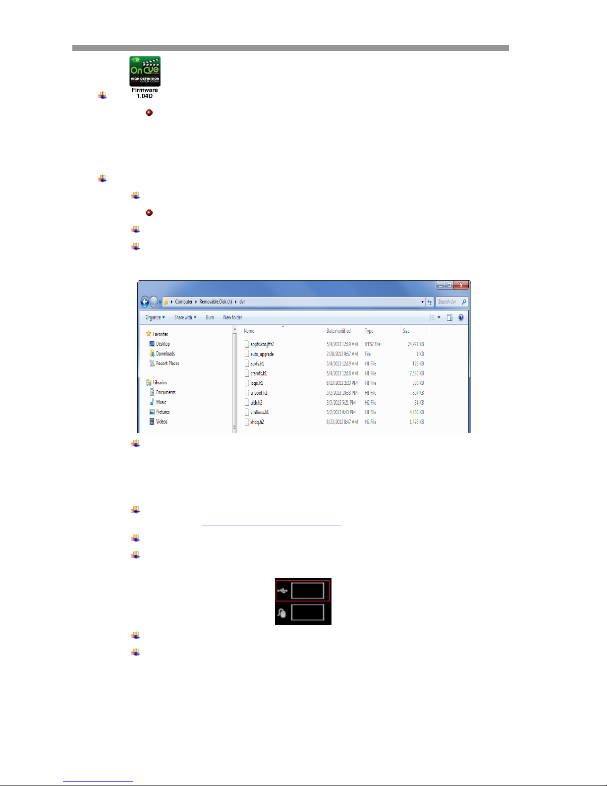
The ‘1.04D’ in the file name is the F/W version number.
Please avoid updating if the version number of F/W file is lower than the current F/W
version.
1.1.1.2 Preparing new F/W in the USB thumb drive
All the required F/W files should be copied under the ‘dvr’ folder. Refer to the following steps:
Plug the USB thumb drive into a PC.
Make a ‘dvr’ folder on the root directory on the USB thumb drive.
The characters, ‘d’,’v’,’r’, in the folder name have to be in lower case not in capital.
Copy the released F/W zip file into the ‘dvr’ folder in the USB thumb drive.
Extract the zip file under the ‘dvr’ folder. Finally all files shouled be located under the ‘USB
thumb drive\dvr’. Refer to the below picture.
Please remove the USB from the PC via Windows ‘Safe Remove Hardware and Eject Media’
feature.
1.1.1.3 Upgrading System
How to update the firmware:
Prepair USB dirve (format in fat32) and create folder with the name “dvr” download updated
firmware from http://vitekcctv.com/Downloads.asp into “dvr” folder
Cycle the DVR’s power (turn DVR Off then On and boot up)
Plug the prepared USB thumb drive in the USB port of DVR. Only the upper USB port in the
Front panel of DVR is allowed to update the F/W.
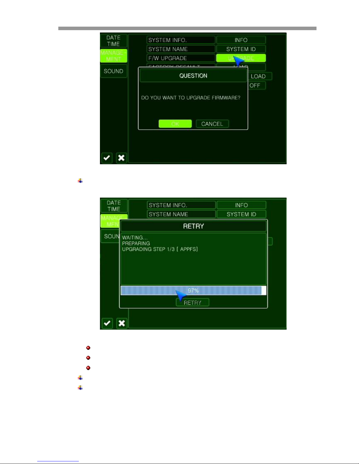
Enter the DVR menu and select “SYSTEM” then “MANAGEMENT”
Select “F/W UPGRADE” and the following image will display
Page 6
VT-HDOC Series
5
Select “OK” and the following image will display
The updating process can take from 1 to 10 minutes.
Don’t remove the USB thumb drive during update.
Don’t’ turn the DVR off during update.
When the update is completed the DVR will reboot
Remove the USB thumb drive from the DVR.
1.1.2 UPDATING FROM THE WEB MENU
Using the web GUI to update the system F/W remotely:
Page 7
VT-HDOC Series
6
For more information on how to access the web GUI, refer to section 7.1, ‘WEB SERVER’ of
this user’s guide.
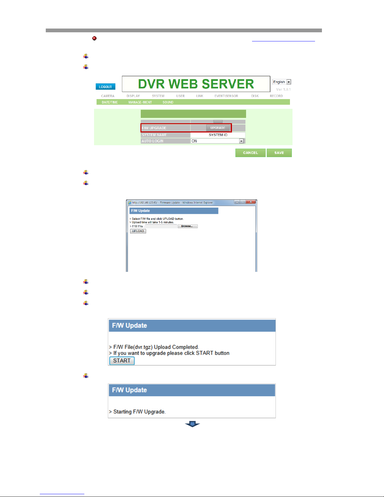
Log in to the web GUI
Go to ‘SYSTEM’ then ‘SYSTEM MANAGEMENT’. Refer to the below picture.
Click the ‘F/W UPGRADE’ button
In ‘F/W Update’ pop-up, click the ‘BROWSE’ button locate and select the firmware.
Choose the provided F/W files which has the file extenstion ‘tar.gz or tgz’.
Click the ‘UPLOAD’ button to upload the F/W to the system.
After the firmware has uploaded, the system will be ready for the update. Click the ‘START’
button to begin the updating processes.
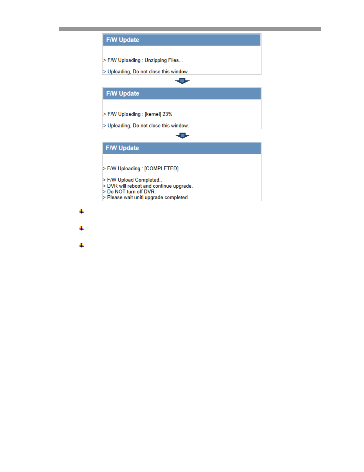
During the update, the progress will be displayed (see below).
Page 8
VT-HDOC Series
7
When the 1
st
stage of updating has finished, [COMPLETE] will be displayed, and the system will
reboot automatically.
After the automatic reboot, the 2
nd
stage of updating will start from the DVR (with the web
connection closed).
The 2
nd
stage updating progress will be shown on the DVR (see following picture).
Page 9

VT-HDOC Series
8
When the whole update is completed, the DVR will restart.
Turning off the power during any stage of the F/W updating process will cause damage to
the system.
Page 10
VT-HDOC Series
9
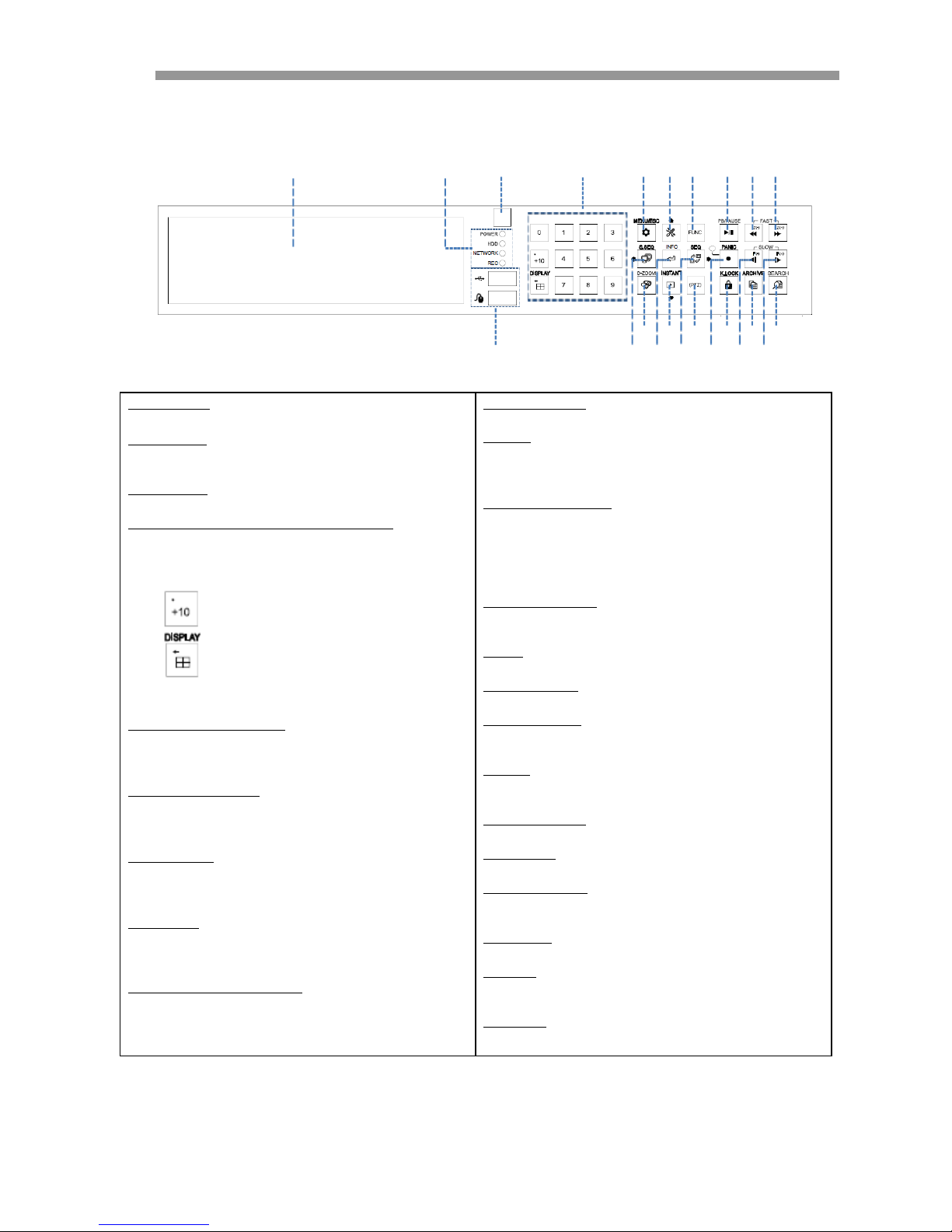
1.2 FRONT AND REAR
1 2 3
4
5
6 7 8
91011
121314
15 16 17
1819202122
23
[Front Type]
Displays the information of the DVR (Stand –By),
Record / HDD read/write and Network transmission.
Infrared signal receiver for the IR remote controller.
Selects the desired channel and show it with the full scale.
Enter the number or numbers required to be input,
Password, IP address, Time & Date and Etc.
[ ] Dot symbol for the input of IP address.
[ ] Back Space, deletes and moves character to
the left. Toggles between various multiple displays. 4
channel-splits screen display.
USB 2.0 ports. Supports functions such as ‘Copy to
USB storage’, ‘F/W Upgrade’, Etc.
USB 1.1 ports. Supports ‘Mouse Operation’
Calls and gets into the main menu.
Returns to previous menu screen.
Exits from various function and menu screens.
Calls and gets into the Tool Bar.
Tilts up in PTZ control mode.
Move the cursor up in the menu.
If you press “Function Key”, function list of DVR will be
displayed. If you press “Function Key + Tool Bar / Up
Key”, video out resolution of HDMI / VGA will be changed.
9. SPOT AUTO SEQUENCE / LEFT
Pans left in PTZ control mode.
Moves the cursor left in the menu screen.
Enters digital zoom mode.
Executes the selected function in the menu screen or
enters the selected submenu.
Accesses the status window from the live screen.
If you press the “Instant playback” key, instant playback
will start from the present time. In multi-screen mode,
channel number 1 will be displayed by default. At full
screen mode, the selected channel will be displayed on
playback.
Activates and deactivates the automatic channel
sequence.
Enters PTZ control mode.
In playback mode, Pause / Play key will toggle.
In playback mode, max X 120 reverse playback speed
supported.
In playback mode, max X 120 forward playback speed
supported.
Activates the panic record mode.
Activates the Key Lock mode.
In playback mode, max X 1/120 slow reverse playback
supported.
Enters the archive menu screen.
In playback mode, max X 1/120 slow forward playback
mode supported.
Enters the search menu screen.
Page 11
VT-HDOC Series
10
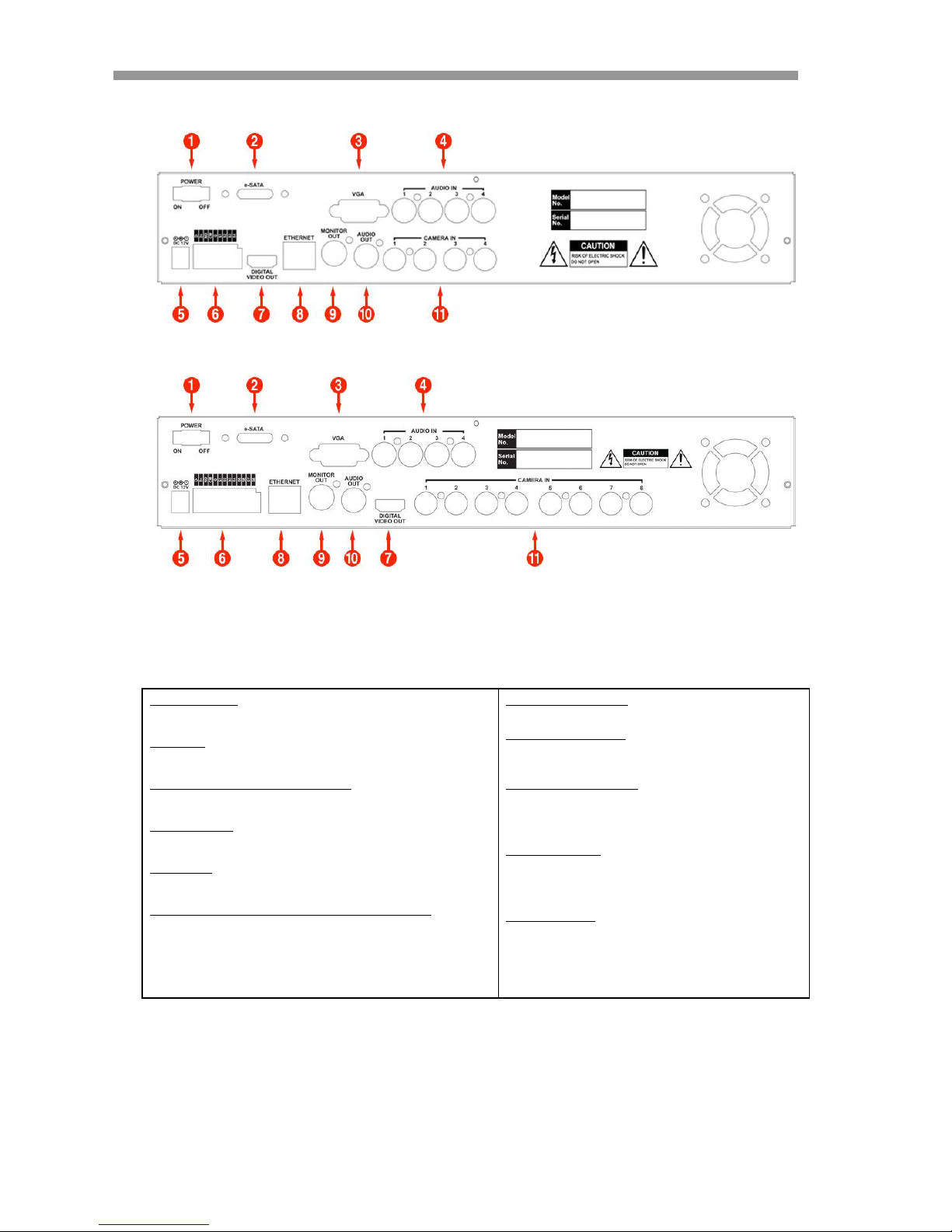
[VT-HDOC4 Rear Connections]
[VT-HDOC8 Rear Connections]
Switch to turn the DVR ON & OFF.
External SATA port.
15-pin D-sub connector for the analog VGA output.
RCA connectors for the audio signal inputs. (Line In)
DC Power socket.
Alarm inputs x 4
RS-485 Signals. (G: Ground, D+: RX/TX + signal, D-: RX/TX-
signal)
Relay output for the relay 1 (NO: Normal Open, NC:
Normal Closed, CM: Common)
HDMI video output for the main monitor.
10/100 Base –T, RJ-45 port for network
connection.
Composite video output for the main monitor.
(BNC)
RCA connector for the audio signal output. (Line
Out)
HD SDI DVR: HD-SDI video inputs for each
camera
Page 12

VT-HDOC Series
11
2. GETTING STARTED
2.1 CONNECT AND SWITCH ON
Connect HD cameras to camera inputs on the back of the DVR.
Connect one or more monitors to the DVR using HDMI, VGA, CVBS.
Connect power to the DVR. Press the power button on the back panel of the DVR to power on the DVR.
[Logo Image]
[Loading System]
As the system boots up, you can view the loading process (see above).
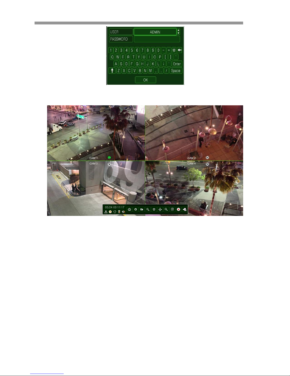
After startup diagnostics are complete, the operator must log-on to the system. The default user name is
“ADMIN”. Using the mouse or channel selection buttons, key in the default password of “1234” and press
the enter button
Page 13
VT-HDOC Series
12
[Log In]
[Live video mode]
The DVR begins normal operation and shows the default display of all 4 channels. The Tool bar at the bottom
of the screen shows current time and date. Tool bar includes Log In-Out, Menu, Archive, Search, Display, PTZ
& Zoom control, log along with panic record.
Page 14
VT-HDOC Series
13
3. TOOL BAR
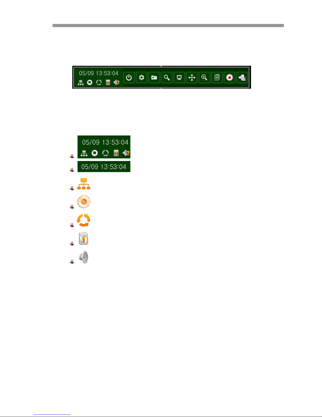
You can view the following Tool Bar when you move the mouse to the bottom of screen or press the “Tool bar
button” on the front panel.
3.1 STATUS DISPLAY
You can check the Current time / Network connection/ USB storage connection/ Auto sequence/ HDD location
currently recorded.
: Shows current time.
: Shows Network connection.
: Shows USB Storage or ODD Drive connection
: Shows Auto sequence Auto Sequence
: Shows HDD location which is currently recorded.
: Shows the selected default audio channel.
Page 15
VT-HDOC Series
14
3.2 LOG OFF
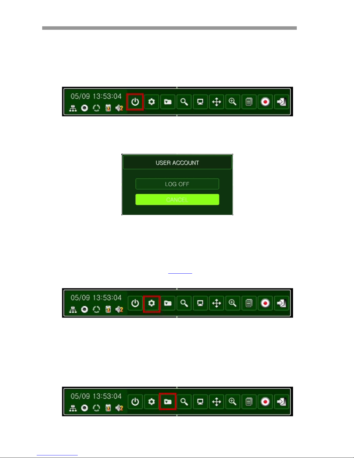
There are two ways to log off. One is a manual log off, and the other is an automatic log off after the
configured time has passed (between 1 and 99 minutes).
[Log-Off by using TOOL BAR]
Press the LOG OFF button to log out the current user.
Once the user has logged out, you can view the log entry in the log window .
In addition, you can configure the automatic log off feature in the Menu Setup:
Menu SetupUserLogOut
3.3 MAIN MENU POP-UP
Press the main menu button to bring up the DVR’s main menu POP-UP.
3.4 ARCHIVE MENU POP-UP
Press the Archive menu button to bring up the Archive menu pop-up
.
Page 16

VT-HDOC Series
15
3.5 SEARCH MENU POP-UP
To search for a particular section of recorded footage, press the SEARCH button.
To protect unauthorized viewing of footage, only authorized users can playback footage.
Page 17
VT-HDOC Series
16
3.6 DISPLAY POP-UP
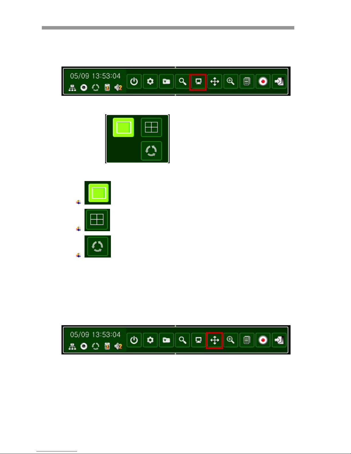
To configure the display mode, press the display button.
You can select Quad / Single/ Auto sequence by selecting the item in pop-up menu.
: Single Screen Mode.
: Quad Screen mode.
: Auto Sequence
3.7 PTZ MODE
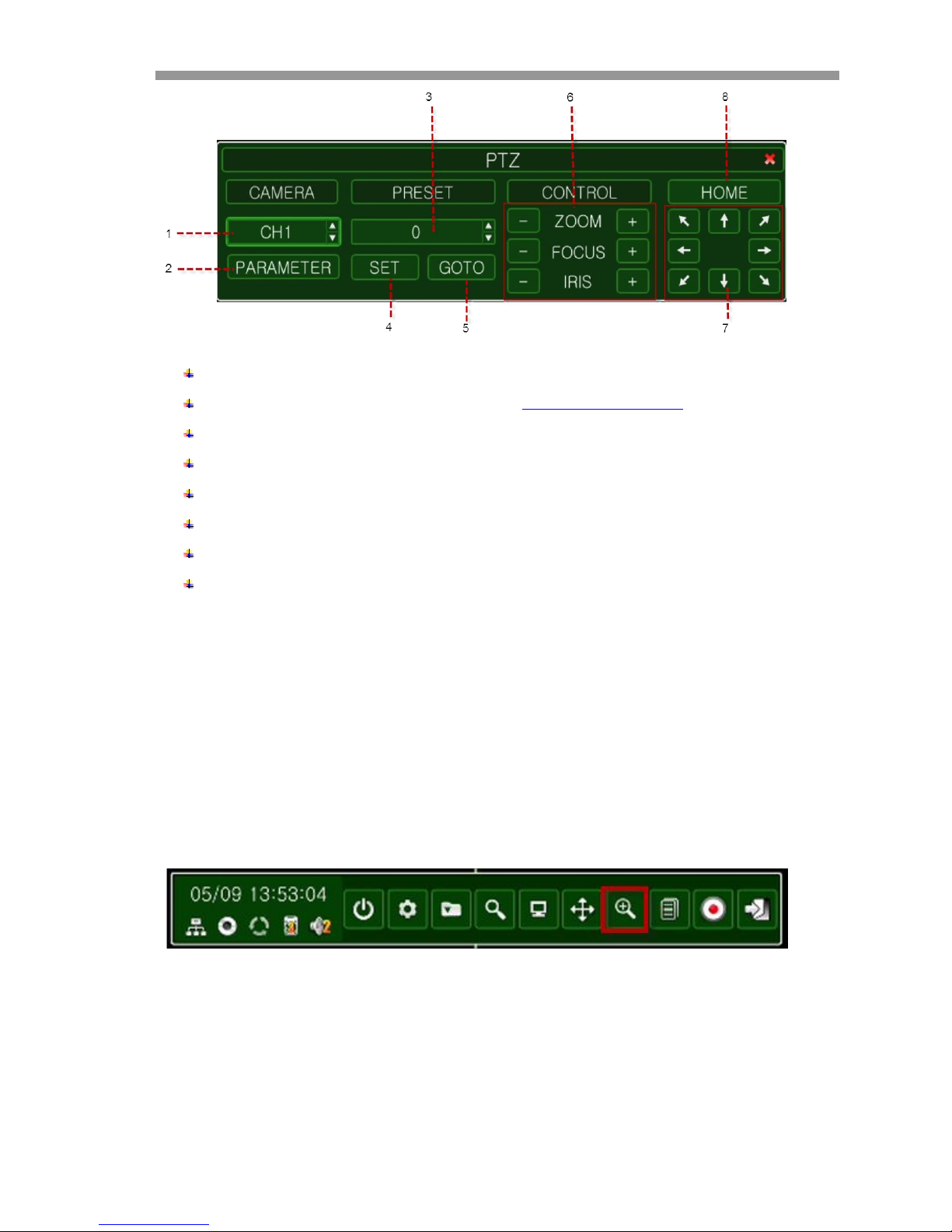
When in quad display mode, the PTZ control panel will be opened for the selected camera (camera that is
highlighted). If there is no highlighted camera, the PTZ control panel is opened for controlling camera 1.
In single display mode, the PTZ control panel is opened for the currently displayed camera.
Page 18
VT-HDOC Series
17
1 : Select channel for PTZ control .
2 : Display PTZ control parameters which are set under the ‘DETAIL’ of PTZ menu settings
3 : Number to configure Preset .
4 : Select current screen as Preset.
5 : Move to configured Preset Number.
6 : Control the value of Zoom/ Focus/ Iris.
7 : Move the PTZ camera to Left/ Right/Top/Bottom
8 : Move to the Home position of PTZ camera.
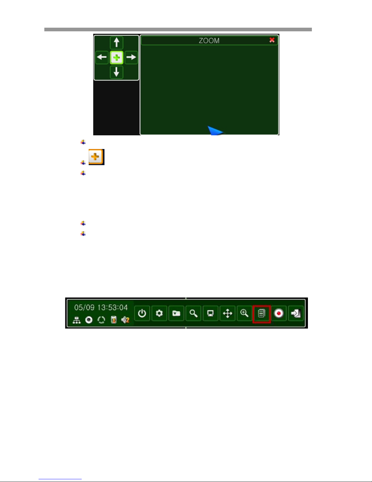
3.8 DIGITAL ZOOM
There are two ways to digitally zoom:
Select the Zoom button on the Tool bar.
Click and drag with the mouse
[Zoom by using the TOOL BAR]
Desired camera should be at Full screen mode, and then select the Zoom button.
NOTE: When selecting the Zoom button while on quad display mode, channel 1 is automatically displayed.
Page 19
VT-HDOC Series
18
1 : You can move Zoom Box
: If you press this button, you can control zoom box by 5 levels.
2 : Currently Zooming screen.
[Zoom by using the Mouse]
At full screen mode, you can select the area to zoom in/out by clicking/holding the left mouse button and
dragging. Clicking on the zoomed screen will return to the original screen.
Digital Zoom is supported for both Live / Play modes.
Digital Zoom is only supported at Full screen mode.
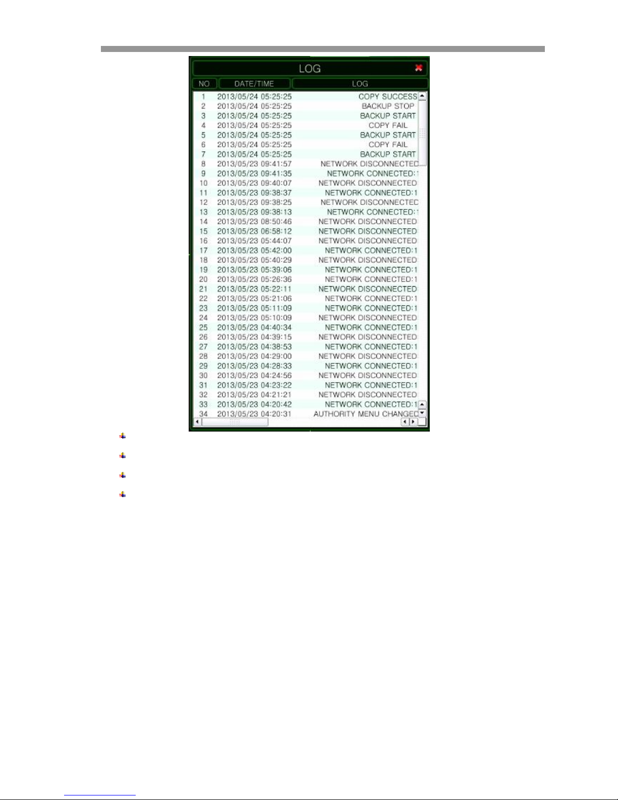
3.9 LOG LIST
You can view the log list by selecting log list button on the Tool bar.
Page 20
VT-HDOC Series
19
1 : Log item number (ordered by date from the most recent. ( Max 10,000 can be recorded)
2 : Date / Time
3 : Log list
Items listed in log list.
Menu Changed
Power ON/OFF
Panic Record ON/OFF
Log In / Off
Client Connect / Disconnect
Time Set: Clock is set by user
Time Adjust: Clock is adjusted by the NTP
Copy: The recorded data is copied out.
ENV Load: Menu setting is loaded from the external storage such as USB stick.
ENV Save: Menu setting is saved to the external storage such as USB stick.
HDD Bad Sector: Bad Sector of HDD or similar access failure happened
HDD Error: Error happened during the HDD I/F but HDD still can be accessed.
HDD Fail: Impossible to recognize or access to HDD any more.
Fan Error:
Page 21
VT-HDOC Series
20
Watch dog
Menu Initialize
HDD Initialize
Media Backup I/O Error
Media Backup I/O Fail
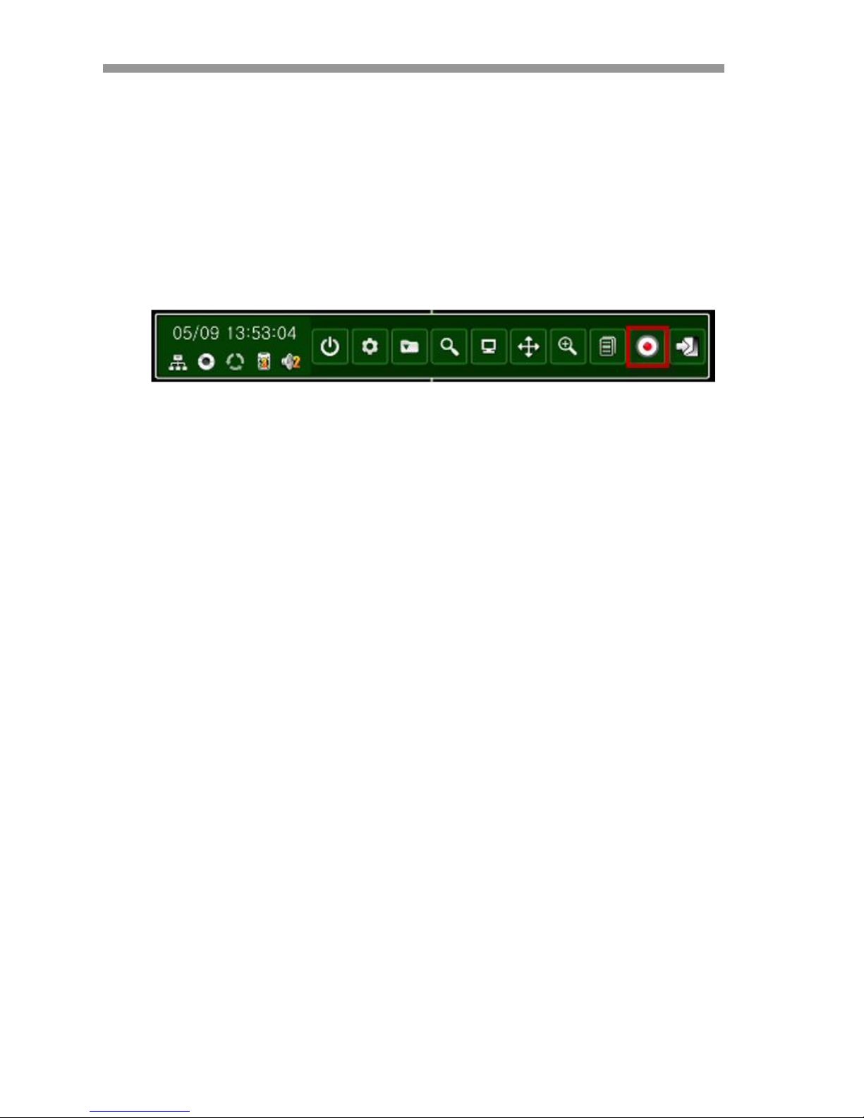
3.10 PANIC RECORD
You can turn on “Panic Record” by selecting the Panic Record button on the Tool bar menu.
PANIC REC START: Starts the panic record mode. Use the Left mouse click to select.
If you turn Panic Record on, recording mode will be changed to the Panic record mode that has already been
configured in record menu.
Panic record will be stopped after the programmed panic record time has passed.
Page 22
VT-HDOC Series
21
4. SEARCH & PLAYBACK
4.1 TIME / CALENDAR SEARCH
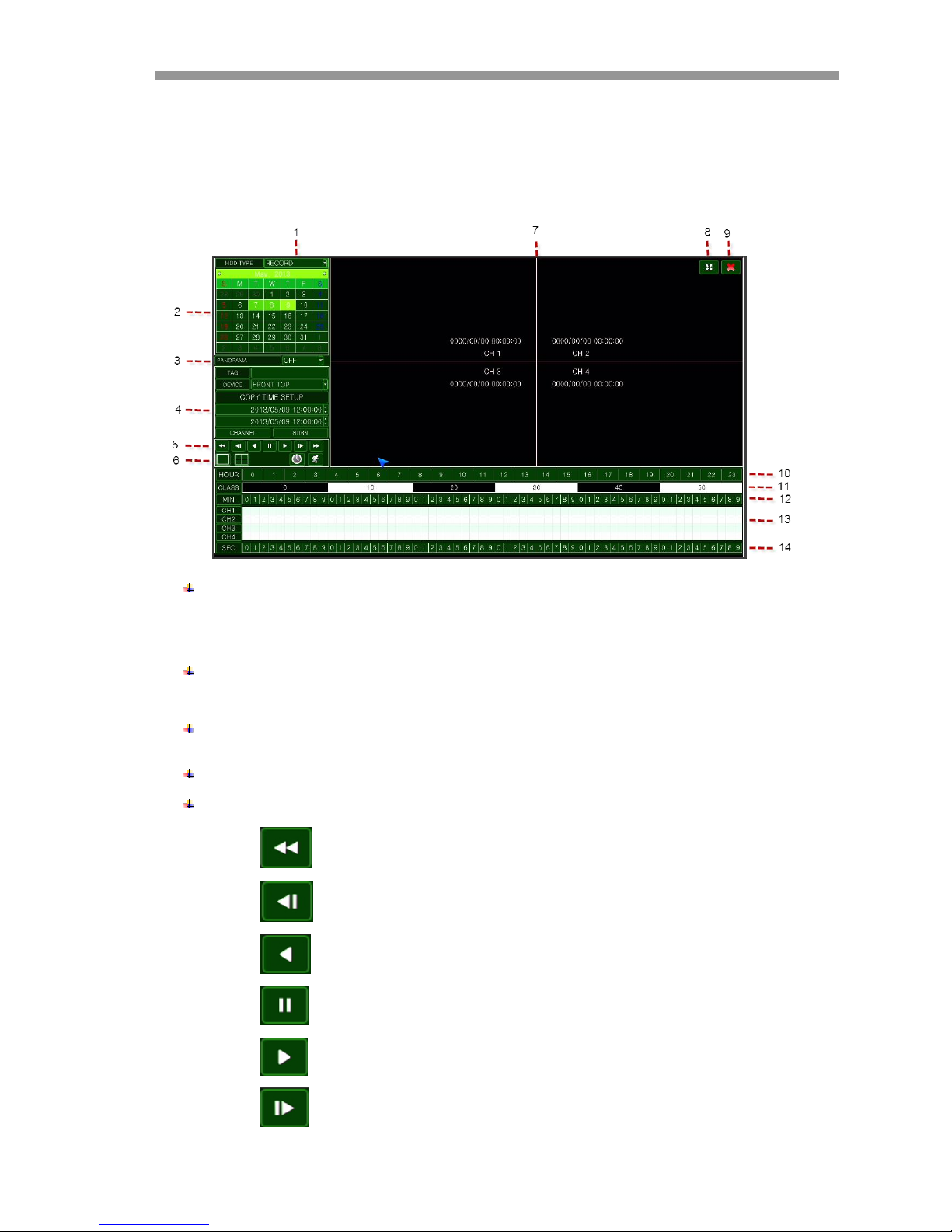
The DVR uses a calendar and timeline search method for quick access to recorded footage.
1 : SEARCH HDD : You can select the HDD to search
RECORD : You can search HDD selected as Record.
MIRRORING : You can search HDD selected as Mirroring.
2 : CALENDAR : Current month will be displayed. Any date that is shaded will contain recorded data.
If you select the date having the recordings, you can make a display of recorded data by hour.
3 : PANORAMA ENABLE (Thumbnail search) : If you enable this, search mode will be changed to panorama
mode.
4 : COPY : You can copy the data to external storage.
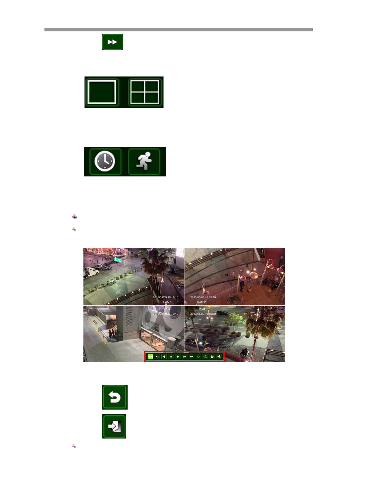
5 : PLAY CONTROL : Playback speed and direction control.
: Reverse Fast Play
: Reverse Slow Play
: Reverse Play
: Pause
: Play
: Slow Play
Page 23
VT-HDOC Series
22
: Fast Play
6 : QUAD / SINGLE : Change the playback screen
QUAD : Quad screen playback mode
SINGLE : Single screen playback mode
TIME / EVENT : You can select “time line screen” or “event list screen”.
TIME : Display Time line
EVENT : Display Event list screen
7: VIDEO WINDOW: Searched video will be displayed here
8 : FULL SCREEN : Full screen mode
You can control the playback screen by using the play control bar.
: Return to Search menu.
: Close playback screen and return to live screen
9 : Returns user to Live mode
Page 24
VT-HDOC Series
23
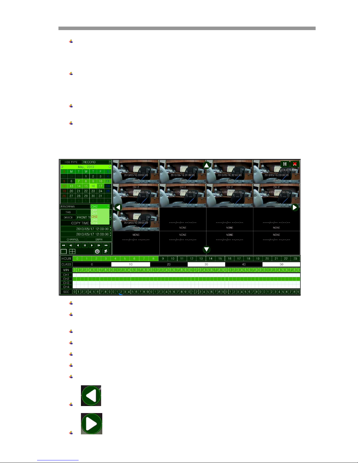
10 : HOUR SELECT LINE: Displays time in Time line mode. If the selected calendar day has recorded data, the
hour’s with data will be shaded
Press the “Front enter key” or use the left mouse button to click on the desired hour; the selected time will be
displayed by minute.
12 : MINUTE SELECT LINE: You can search the data by minute. If desired minute has recorded data, the
minutes with data will be shaded
Press the “Front enter key” or use the left mouse button to click on the desired minute, playback will be started
from selected time.
13 : RECORD DATA STATUS: You can view recorded data from each channel. The shaded area shows
recorded data.
14 : SECOND SELECT LINE: You can select the data by second after playback has started. Press the “Front
enter key” or use the left mouse button; the playback time will be moved to selected second.
4.2 PANORAMA SEARCH (Thumbnail search)
If you enable PANORAMA, search mode will be changed to PANORAMA (Thumbnail) Mode.
Select a date from the Calendar, panorama playback will be started from first recorded data from the selected
date.
Select channels 1 – 4
16 way grid will be displayed at first panorama search mode in 1 hour segments
You can make a panorama search by minute by clicking on down arrow or double clicking any image
You can make a panorama search by second by clicking on down arrow or double clicking any image
To start playback select image to start from then right click and from the pop-up window select play
: Shows previous panorama.
: Shows next panorama
Page 25

VT-HDOC Series
24
: Changes between Hours, Minutes, and Seconds
: : Changes between Hours, Minutes, and Seconds
Page 26
VT-HDOC Series
25
4.3 EVENT SEARCH
.
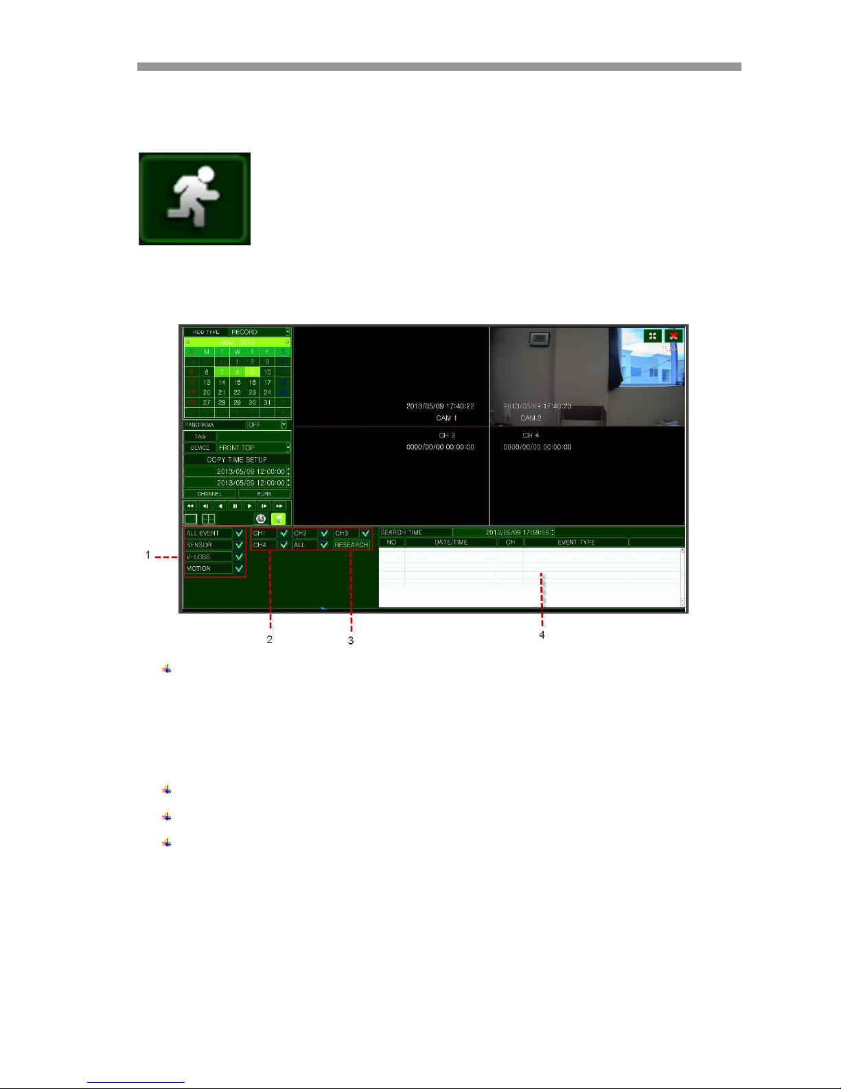
1 : You can configure which Event Type will be displayed in Event list .
ALL EVENT : Display all events.
SENSOR : Display Sensor Event.
VIDEO LOSS : Display Video loss Event.
MOTION DETECTION : Display motion Event .
2 : You can select which channel will be displayed in Event list.
3 : With the search condition defined in the above 1 & 2, execute the event search again.
4 : Events from most recently triggered will be displayed.
DATE/TIME : Display Event triggered time.
CHANNEL : Display Event channel
EVENT TYPE : Display Event type.
Page 27
VT-HDOC Series
26
4.4 COPY
There are two ways to input the copy time.
One is that you can manually enter the desired ‘From’ and ‘To’ times in the ‘COPY’ panel. The other is taking
the ‘Start time’ and ‘End time’ by right-clicking on the required time in the ‘MINUTE SELECT BAR’
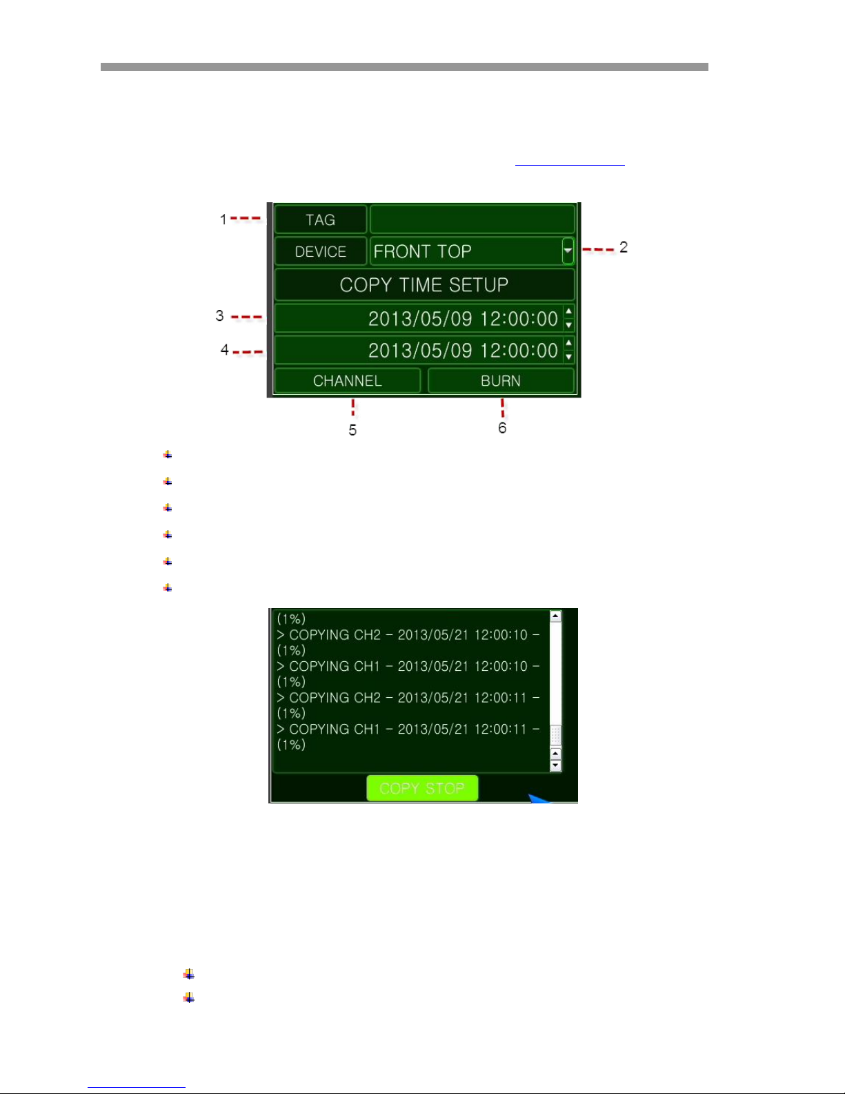
1 (TAG NAME) : You can name the data folder that will be copied to the USB.
2 (DEVICE) : You can select the port for USB to copy.
3 : You can select the start date and time to copy.
4 : You can select the end date and time to copy.
5 : You can select which channel(s) to copy.
6 : Start Copy.
Shows copy progressing.
You can stop the copy.
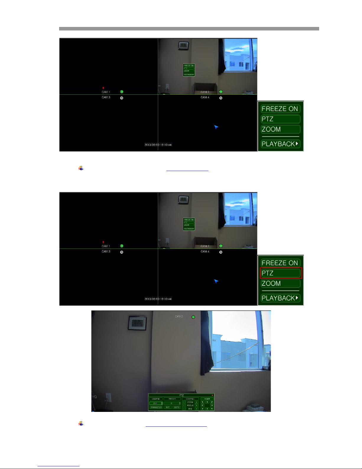
5. QUICK MENU
If you are using a USB mouse to control the DVR, pressing the right button of mouse will bring up the Quick
Menu.
FREEZE ON : If you select Freeze button, all screens will be stopped.
FREEZE OFF : You can release Freeze mode by pressing the right mouse button, and selecting
Freeze Off.
Page 28
VT-HDOC Series
27
PTZ: Selecting PTZ will bring up the PTZ control screen. PTZ can only be controlled by an
authorized user.
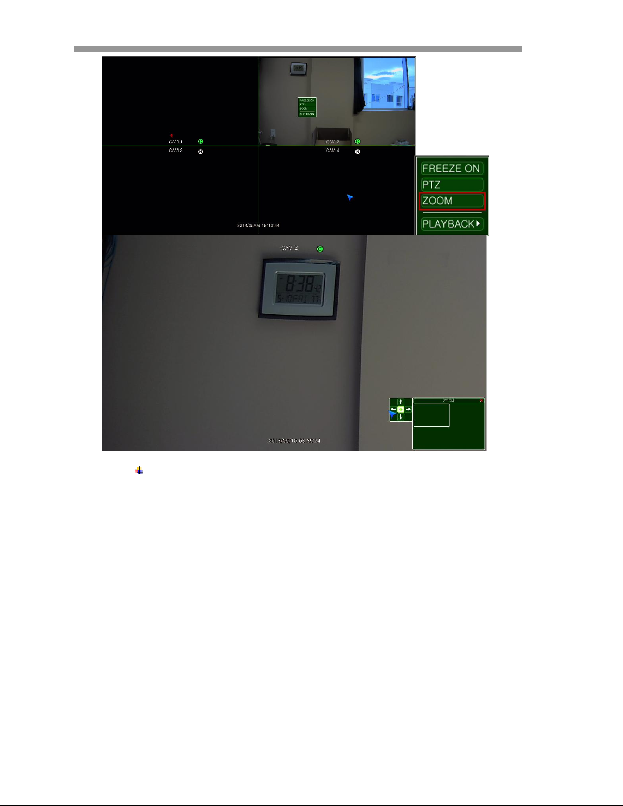
ZOOM : This executes the digital zoom control screen.
Page 29
VT-HDOC Series
28
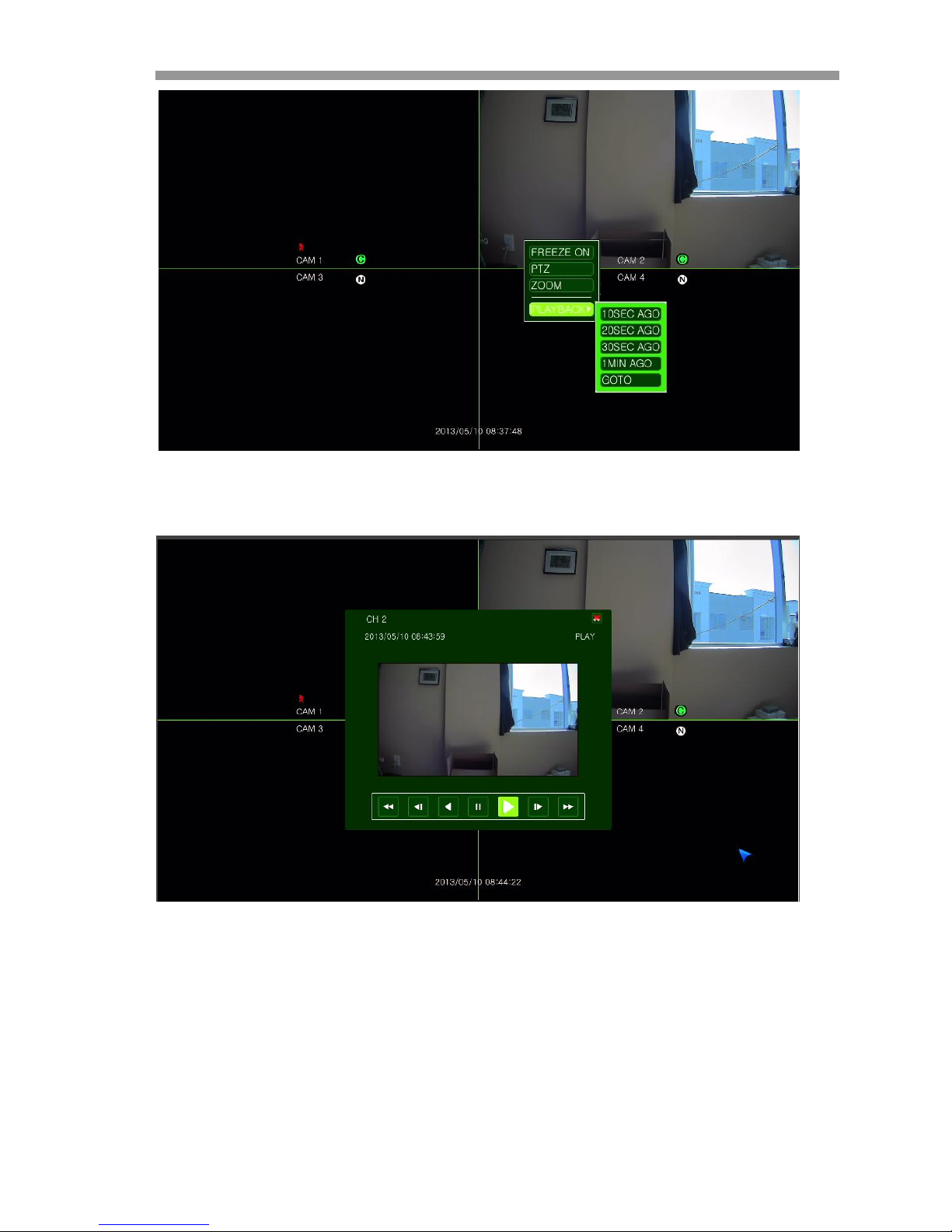
INSTANT PLAYBACK: Selecting PLAYBACK will allow the user to view instant playback of the
selected camera from 10, 20, 30 seconds or 1 minute ago. If GO TO is selected the user can
select the time they wish to view.
Page 30
VT-HDOC Series
29
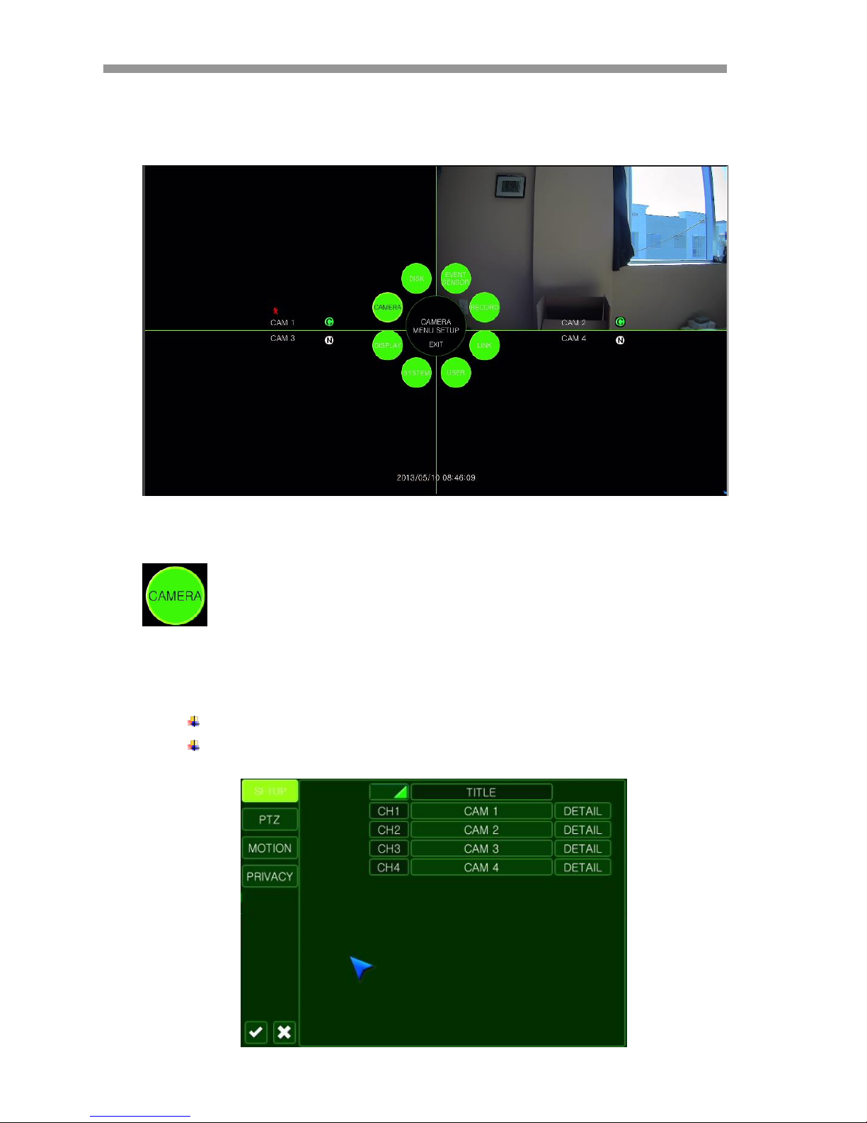
Once the instant playback time has been selected, the instant playback window will pop-up (see below
picture).
Page 31
VT-HDOC Series
30
6. HOW TO CONFIGURE
To view the setup menu, press menu button on the Tool Bar. The following screen will be displayed:
6.1 CONFIGURING CAMERA
To set-up the various camera options, highlight CAMERA and press ENTER.
6.1.1 SETUP
TITLE: For each camera, a title of up to 8 characters can be set using the virtual keyboard.
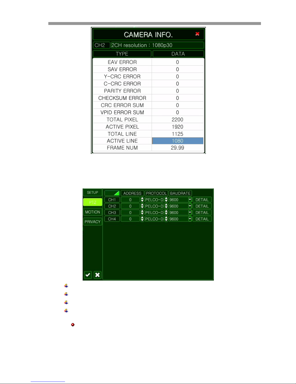
DETAIL: Click the ‘DETAIL’ button at the right side of each channel will open the ‘CAMERA
DETAIL INFO.’ window and show the detail HD-SDI camera information such as below.
Page 32
VT-HDOC Series
31
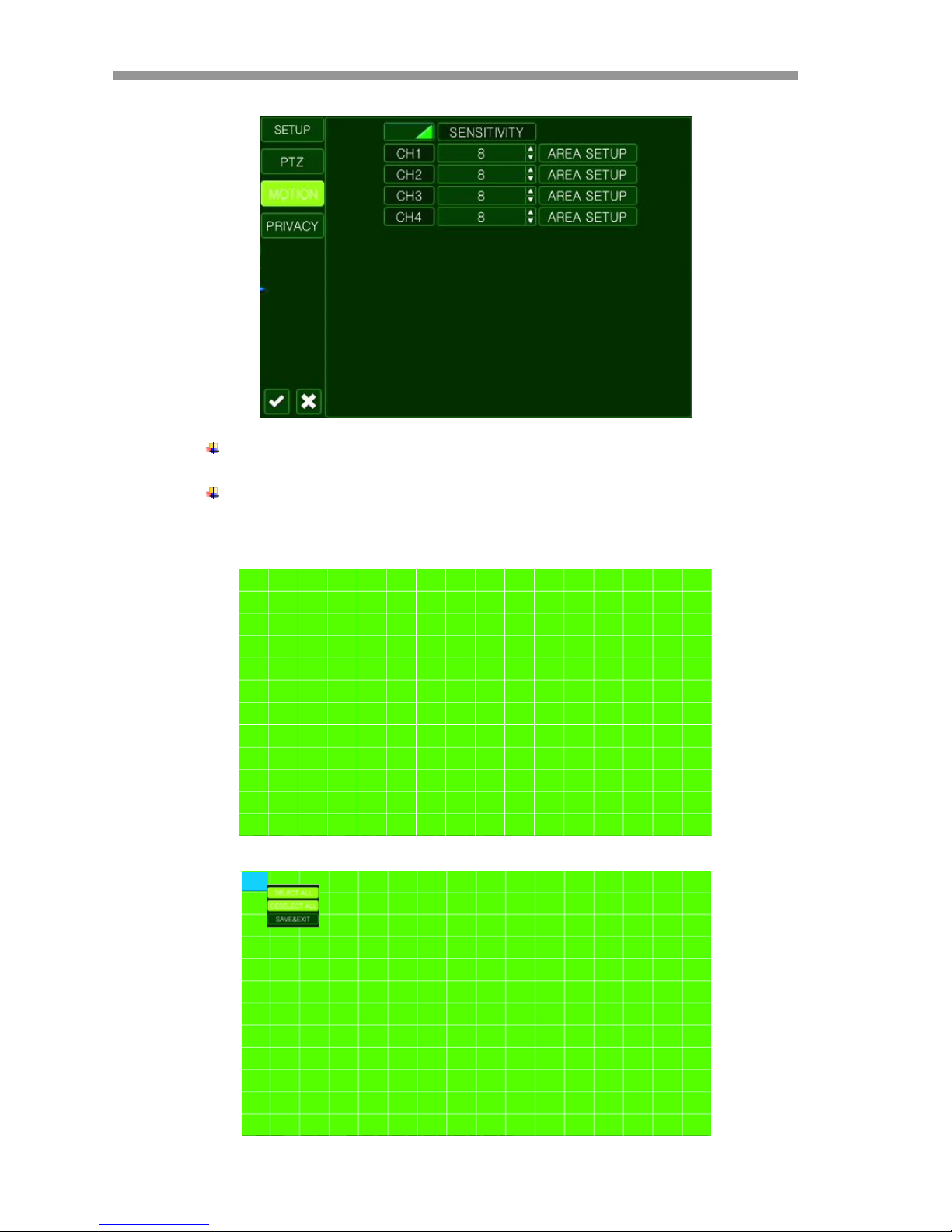
6.1.2 PTZ
ADDRESS: The unique ID of the PTZ device.
PROTOCOL: The protocol of the PTZ device.
BAUD RATE: The baud rate of the PTZ device.
PTZ properties can also be adjusted for each channel by selecting DETAIL and pressing ENTER.
Auto Focus, Auto IRIS, P/T speed, zoom speed, focus speed, IRIS speed
Note that some settings, such as AUTO FOCUS, may not be compatible with particular PTZ
equipment. If this is the case, changing this value will have no effect on PTZ control.
Page 33
VT-HDOC Series
32
6.1.3 MOTION
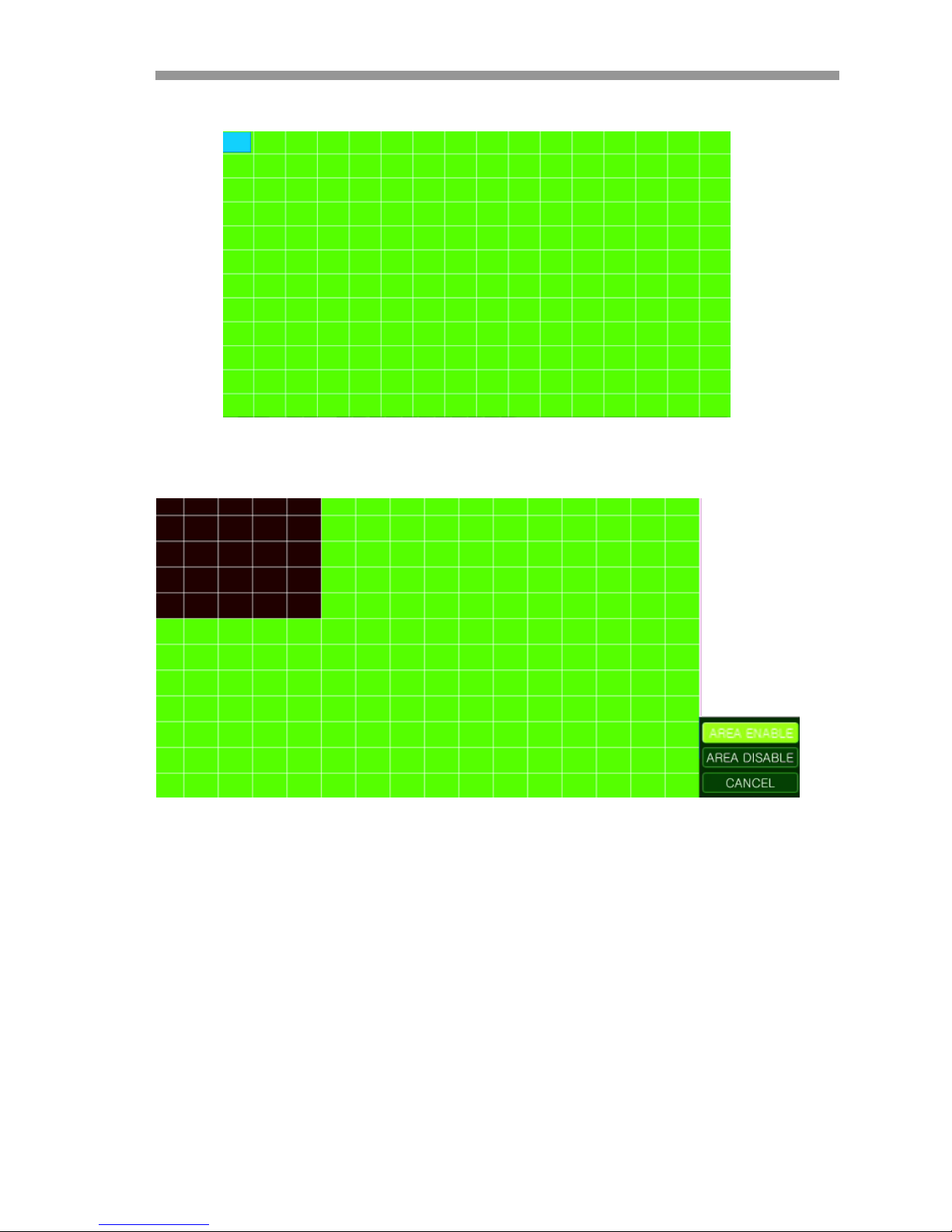
SENSITIVITY: Between 1 (Lowest) and 10 (Highest) determines the degree of sensitivity of
motion dectection.
AREA SETUP: Choosing this option allows the operator to define which areas of the image are
monitored for motion detection. Green grid squares represent detection areas, blank areas are
ignored. The default is that motion will be detected across the entire image.
To quickly select or deselect the entire grid, use the Right mouse click to bring up the motion menu.
Page 34
VT-HDOC Series
33
To select or deselect specific areas, use the left mouse click. Clicking on each cell toggles the setting to be
enabled or disabled.
.
By dragging with the left mouse button down, the rectangle area can be selected. Selecting ‘AREA ENABLE’
or ‘AREA DISABLE’ after dragging will define the activity of the selected area. Refer to the below picture.
Repeat the above sequence as necessary to mask-off or include other areas of the image
Once the detection area has been defined, choose SAVE & EXIT to save the area and return to the motion
setup menu
Page 35

VT-HDOC Series
34
Page 36
VT-HDOC Series
35
6.2 CONFIGURING DISPLAY
To set-up the various display options, highlight DISPLAY and press ENTER.
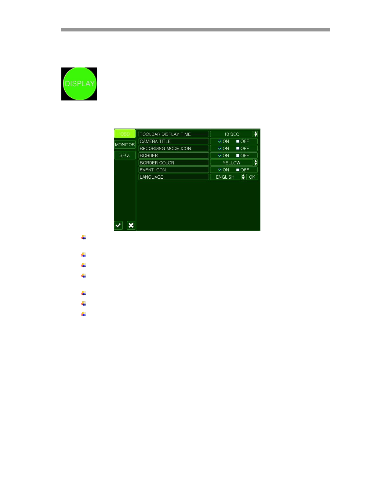
6.2.1 OSD
STATUS BAR TIMEOUT: Turns the Tool bar at the bottom of the live display to ALWAYS ON or
sets the auto-off delay time.
CAMERA TITLE: Determines whether the camera title is displayed.
RECORDING MODE ICON: Determines whether the recording status is shown
BORDER: Determines whether there is a border around each channel in multi screen display
mode.
BORDER COLOR: If the border is ON, the operator can choose the color.
EVENT ICON: Determines whether the event icon is displayed.
LANGUAGE: Select the language of display.
Page 37
VT-HDOC Series
36
6.2.2 MONITOR
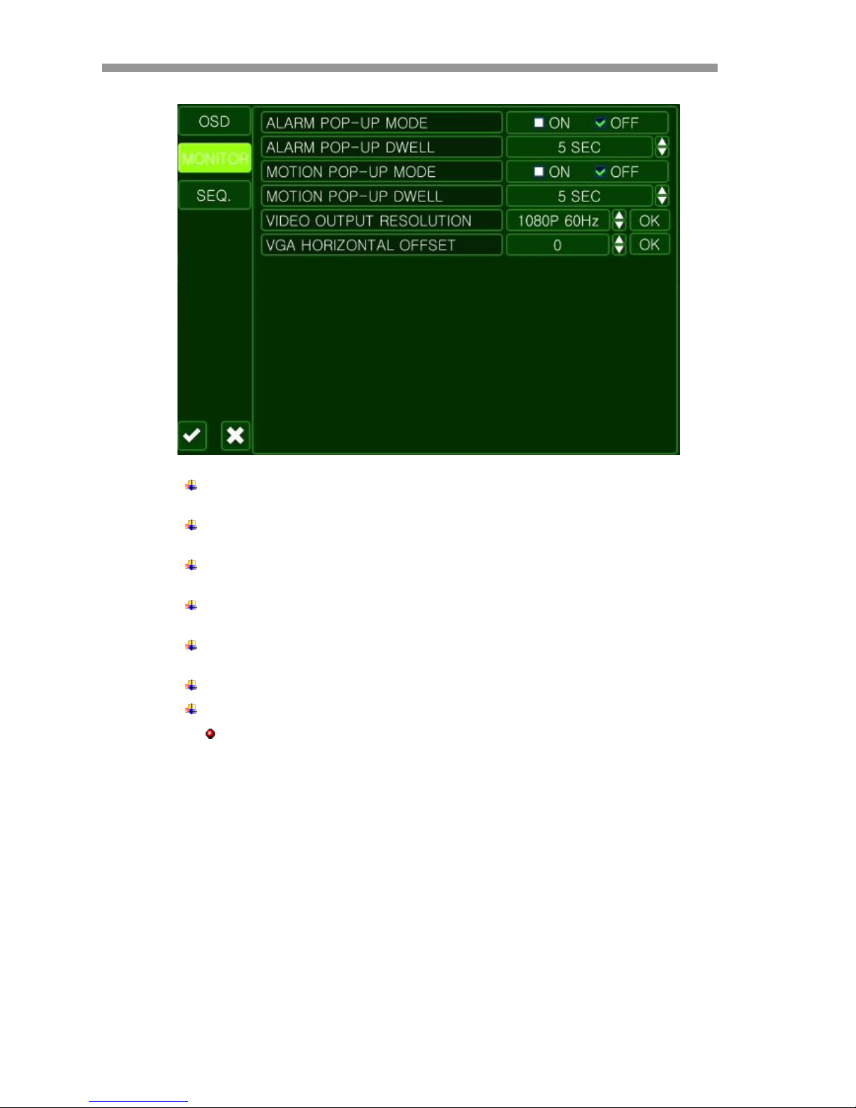
ALARM POP-UP MODE: When set to ON, an alarm input will cause the associated channel to
display full screen.
ALARM POP-UP DWELL: Determines how long the full screen popup is displayed after an alarm
input. If the alarm condition continues, the popup screen is displayed constantly.
MOTION POP-UP MODE: When set to ON, motion detection will cause the associated channel
to display full screen.
MOTION POP-UP DWELL: Determines how long the full screen pop-up is displayed after motion
detection. If motion continues, the popup screen is displayed constantly.
MAIN VIDEO OUTPUT MODE : You can configure video output resolution of main video
480I / 576I / 800x600 / 1280x1024 / 1080P 60Hz / 1080P 50Hz.
OK : Press the OK button to check the configured video output.
ADJUST MAIN VGA H POSITION : You can control the value of VGA video output .
Note: Available only when a VGA monitor is connected.
Page 38

VT-HDOC Series
37
6.2.3 SEQUENCE
SEQUENCE DWELL: The time that each screen is displayed in a sequence operation.
Page 39
VT-HDOC Series
38
6.3 CONFIGURING SYSTEM
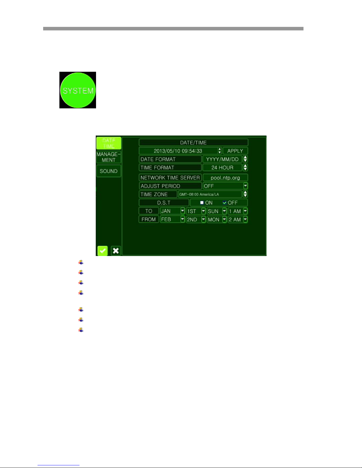
To set-up the various system options, highlight SYSTEM and press ENTER.
6.3.1 DATE/ TIME
DATE&TIME: Allows the operator to set or modify the current date & time.
DATE FORMAT: Determines how the date is displayed.
TIME FORMAT: Determines how the time is displayed.
NETWORK TIME SERVER SETUP: If the DVR is connected to the Internet, you can synchronize
the time and date with a Network Time Sever.
ADJUST PERIOD: Configure how often the DVR synchronizes with the Network Time server.
TIME ZONE SETUP: Should be set according to the region that the DVR is used in.
D.S.T.: When set to ON, the DVR will automatically adjust the time by one hour on the relevant
date in spring and autumn
From : D.S.T : Start time of Daylight Savings Time
To : D.S.T: End time of Daylight Savings Time.
6.3.2 MANAGEMENT
Page 40
VT-HDOC Series
39
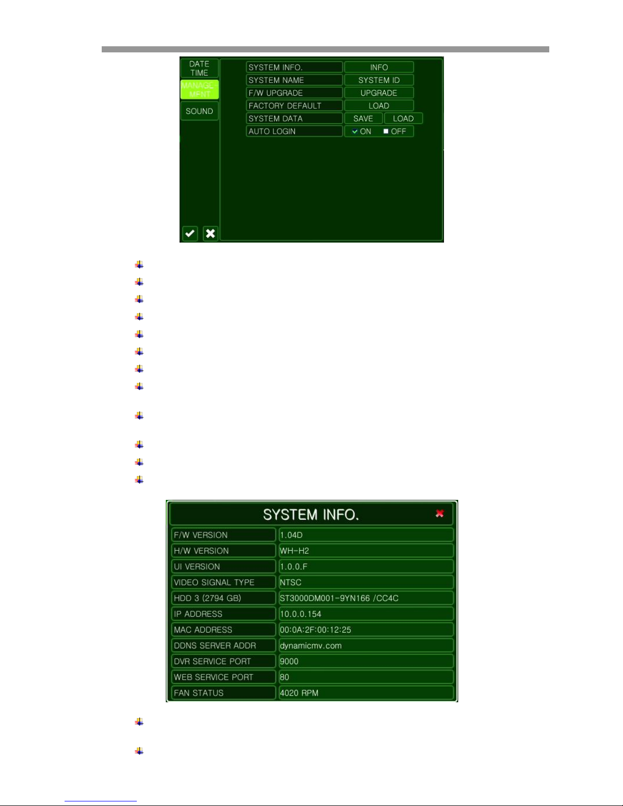
SYSTEM INFORMATION: Select INFO to display
F/W VERSION: Shows the firmware version of the DVR
H/W VERSION: Shows the hardware version of the DVR.
UI VERSION : Shows the UI version of the DVR
VIDEO SIGNAL TYPE: The DVR can be selected between PAL and NTSC via a selector
HDD1: Shows the hard drive 1 capacity installed.
HDD2: Shows the hard drive 2 capacity installed.
IP ADDRESS: Shows either the manual IP address entered in NETWORK setup or the IP address
assigned by a DHCP server if enabled.
MAC ADDRESS: Shows the MAC (Media Access Control) address of the DVR. It is unique – no
other network device has this MAC address.
DDNS DOMAIN NAME: If DDNS is enabled, the host DDNS server is specified here.
DVR SERVICE PORT: The port number the DVR uses for internal networks.
WEB SERVER PORT: The port number that the DVR uses to support remote connections.
SYSTEM NAME: A system name of up to 15 characters can be defined. It is used so that
notification emails can be identified.
F/W UPGRADE: Firmware updates may be released periodically to enhance system
Page 41
VT-HDOC Series
40
performance and add extra features. The operator can upgrade the firmware using a USB
memory stick.
Note: To upgrade firmware, you have to use the top USB port.
FACTORY DEFAULT: Factory default settings can be loaded.
SYSTEM DATA: System settings can be saved to a USB memory stick. The settings can be
reloaded in case of accidental factory reset or can be transferred to another DVR if multiple
units need to be installed with the same settings. All information is saved including network
settings and system name.
Note: You have to use top port of USB ports for System data backup.
AUTO LOGIN: Toggles the Auto Login feature ON/OFF
6.3.3 SOUND
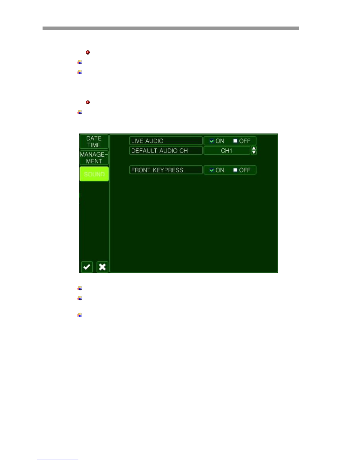
LIVE AUDIO: If you select “on”, Audio output is available at Live mode.
DEFAULT AUDIO CHANNEL: Specify which one of the 4 AUDIO INPUTS is the default audio
when the DVR is in quad screen mode.
FRONT PANEL KEYPRESS: When set to ON, each front panel button press is confirmed by a
beep. This setting will also turn the IR Remote confirmation beep on or off .
Page 42
VT-HDOC Series
41
6.4 CONFIGURING USER
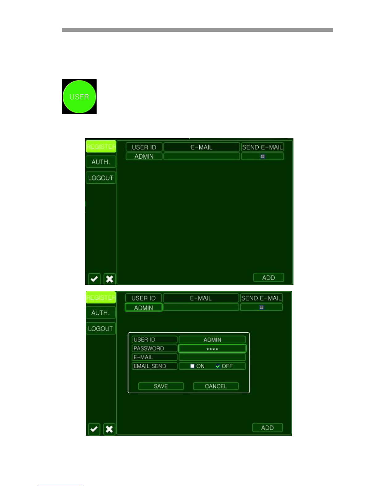
To set-up the User Authority options, highlight USER and press ENTER
6.4.1 USER REGISTER
Page 43
VT-HDOC Series
42
By default the DVR is configured with a USER ID of ADMIN belonging to the ADMIN group and
with a password of 1234.
As well as the ability to add new users, existing user’s defaults can be modified.
The maximum number of users that can be created is 10.
To modify user details, double-click the user with the blue cursor or highlight the user and press ENTER. The
EDIT screen appears.
USER ID: Edit the user ID using the virtual keyboard. (Max 10 characters).
PASSWORD: Change the password using the virtual keyboard. (Max 8 characters)
Please note: To delete the existing password use “CLEAR” on the virtual keyboard.
E-MAIL: Enter the user’s email address if email notifications are required.
E-MAIL SEND: Enable or disable email notification for the particular user.
NOTE: Maximum 10 users can be registered.
NOTE: Any user can be deleted except the default ADMIN user.
6.4.2 USER AUTHORITY
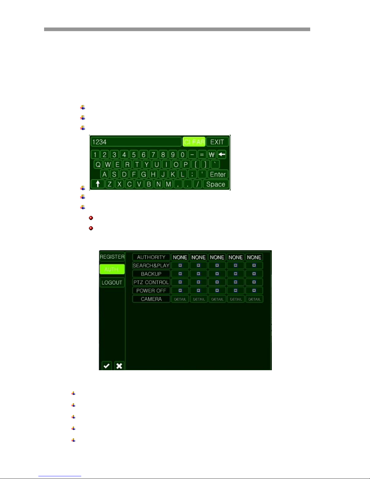
User authority (except ADMIN) can be selected.
Search & Play : authority to enter Search Menu/ Instant Play
Archiving : authority to enter Archive Menu
PTZ Control : authority to enter PTZ Control menu
Power OFF : authority to Power Off
Camera: authority to see specified cameras. Select DETAIL to assign camera access.
Page 44
VT-HDOC Series
43
6.4.3 LOG OUT
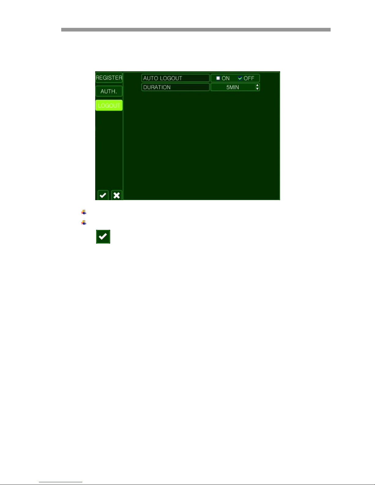
AUTO LOGOUT: Selects if auto log-out is ON or OFF.
DURATION: If auto logout is set to ON this determines the time. (in 1 - 10 Min)
Press APPLY to save settings
Page 45
VT-HDOC Series
44
6.5 CONFIGURING NETWORK
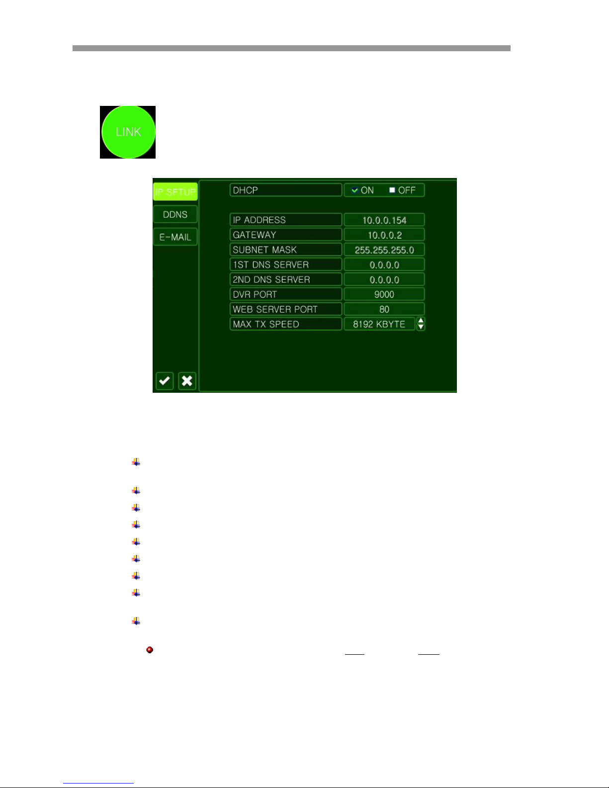
To set-up the Network options, highlight LINK and press ENTER.
6.5.1 IP SETUP
DHCP: When selected, the DVR will obtain an IP address automatically if connected to a DHCP
server or router.
IP ADDRESS: If DHCP is not being used the IP address can be manually set.
GATEWAY: If DHCP is not being used the Gateway can be manually set.
SUBNET MASK: If DHCP is not being used the subnet mask can be set manually.
1ST DNS SERVER: If DHCP is not being used the 1st DNS server can be manually set.
2ND DNS SERVER: If DHCP is not being used the 2nd DNS server can be manually set.
DVR PORT: The port number that the DVR uses to support the remote software.(default 9000)
WEB SERVER PORT: The port number that the DVR uses for a remote connection from Internet
Explorer or other web browsers. (default 80)
MAX TX SPEED: Specifies the maximum bandwidth that the DVR can use during a remote
connection.
NOTE: In order to view your DVR remotely you must port forward BOTH the DVR Port (the
default is 9000) and the WEB SERVER PORT (the default is 80). If you need assistance
with port forwarding, please reference your router’s manual or contact your Network
Administrator/IT Professional.
Page 46
VT-HDOC Series
45
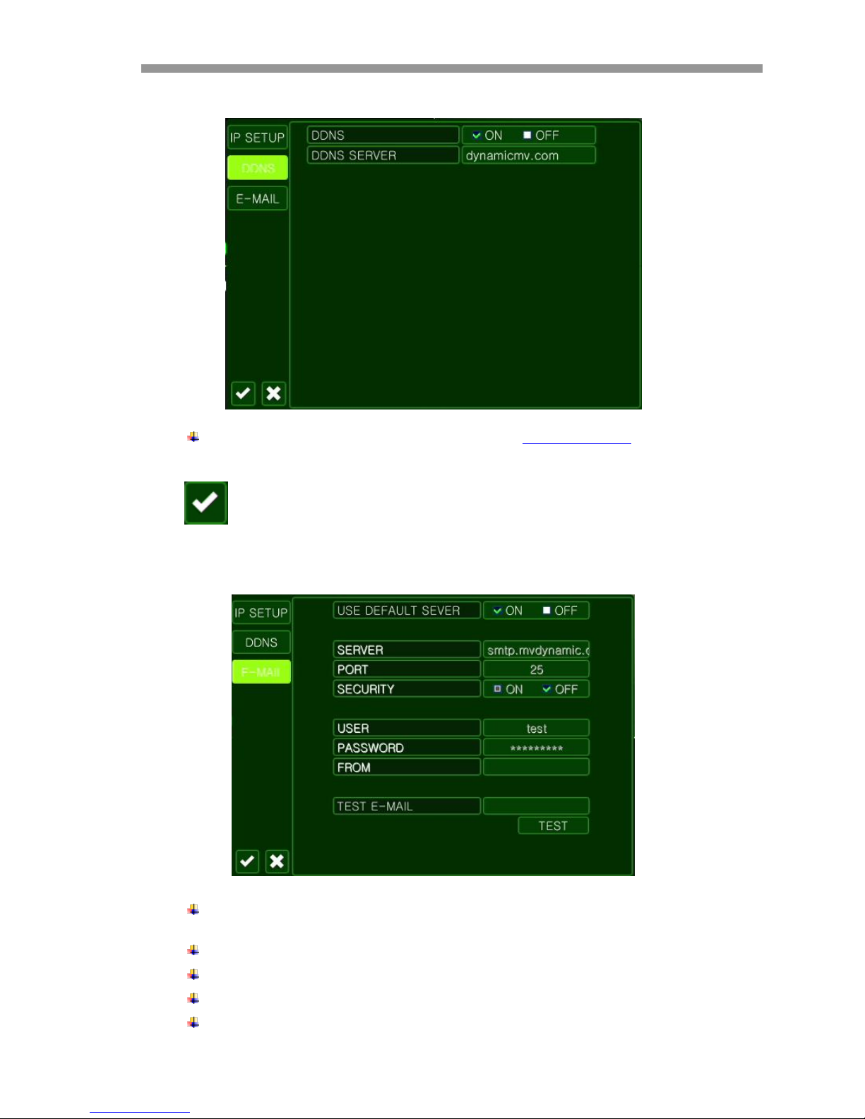
6.5.2 DDNS
DDNS: When enabled, the DVR can be accessed through a dynamic DNS server. Commonly
used if a broadband connection does not have a static IP address.
Press to save settings.
6.5.3 EMAIL
USE DEFAULT SERVER: Selects On or OFF. If you turn Default sever as ON, mail will be sent by
the default mail server .
SERVER: The SMTP outbound email server that should be used to send email notifications.
PORT: The outbound email port number.
SECURITY: Set to OFF if the SERVER does not require a username and password to connect.
USER: Enter a username to identify the DVR in email messages.
Page 47

VT-HDOC Series
46
PASSWORD: If SECURITY is set to ON, enter the password here.
FROM: Input an email address or text.
TEST: Send a test e-mail with the specified server information to verify the delivery.
Page 48
VT-HDOC Series
47
6.6 CONFIGURING RECORD
To set-up the various recording options, highlight RECORD and press ENTER.
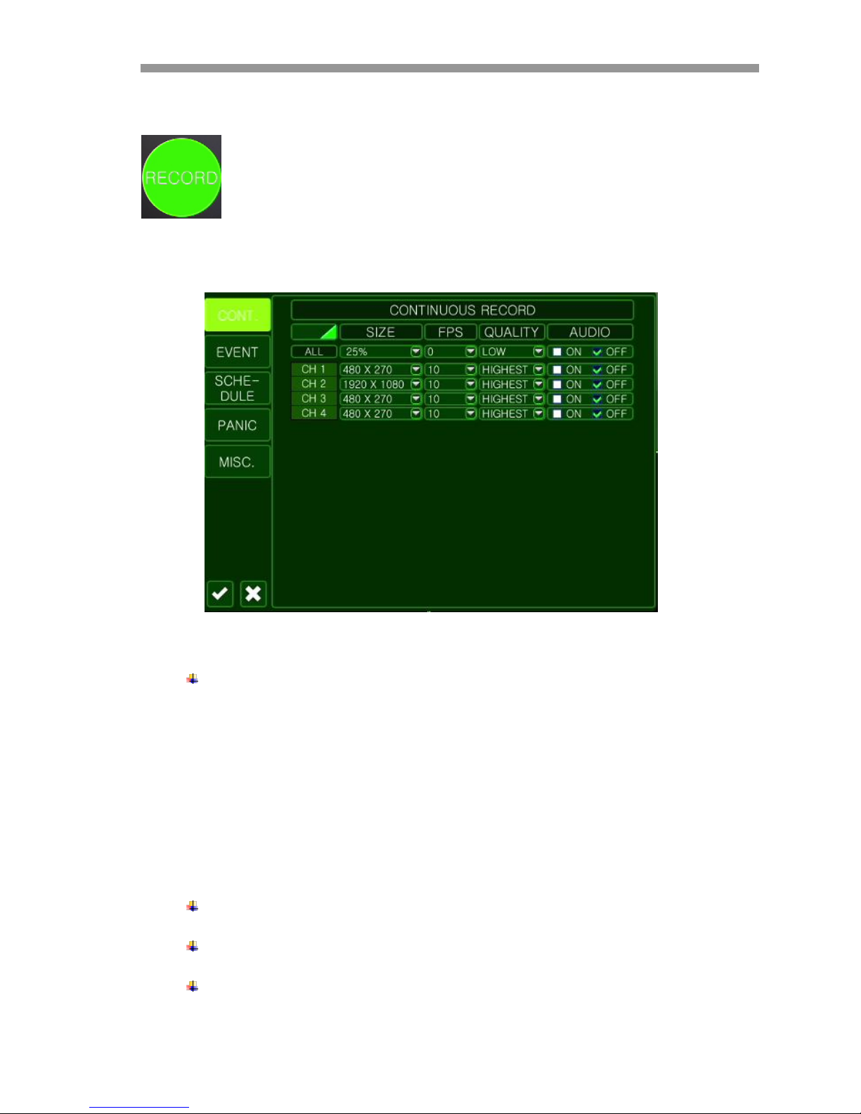
6.6.1 CONTINUOUS
You configure Continuous Record mode.
SIZE : You can select what resolution of video will be recorded as follows;
1080p Camera Input : 1920x1080 / 960x540 /480x270
720p Camera Input: 1280x720 / 640x360/320x180
ALL: Set the resolution for all channels
The resolution setting value is displayed as a percentage of the input resolution of each
camera. This is because there be could multiple cameras with different inputs
connected i.e. 720p camera and 1080p camera inputs.
25%: 480x270 for 1080p input, 320x180 for 720p input
50%: 960x540 for 1080p input, 640x360 for 720p input
100%: 1920x1080 for 1080p input, 1280x720 for 720p input
FPS : NTSC : You can select recording frame rate as 0 / 1 / 2 / 4 / 5 / 8 / 15 /30 at NSTS mode or
0 / 1 / 2 / 4 / 5 / 7 / 13 / 25 at PAL mode.
QUALITY : You can select the recording video quality as 5 levels; Low / Standard / High /
Highest / Super
AUDIO : If you select “ON”, audio data will be recorded.
Page 49
VT-HDOC Series
48
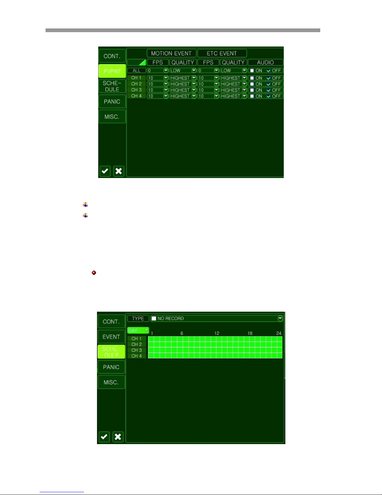
6.6.2 EVENT
For triggered events, you can configure the recording conditions:
MOTION EVENT : You can configure the recording condition when motion is triggered.
ETC EVENT : You can configure the recording condition for Alarm / V-Loss.
FPS : NTSC : You can configure frame rate as 0 / 1 / 2 / 4 / 5 / 8 / 15 /30 at NTSC Mode or 0
/ 1 / 2 / 4 / 5 / 7 / 13 / 25 at PAL mode.
QUALITY : You can configure the video quality at 5 levels: Low / Standard / High /
Highest / Super.
Audio : If you select “ON”, audio data will be recorded.
The recoding resolution for an event recording follows the size in the CONTINUOUS
record setting.
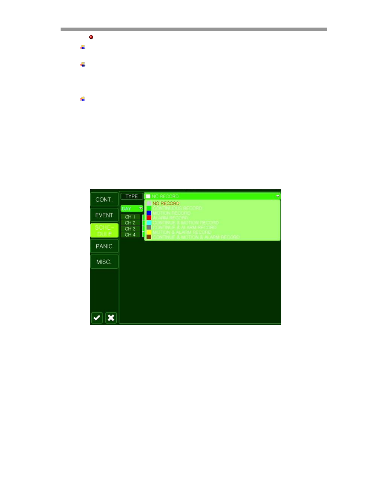
6.6.3 SCHEDULE
You can configure the schedule recording mode as either Day or Week.
Page 50
VT-HDOC Series
49
Day or Week mode is set under the ‘MISC ’ menu under RECORD setup page.
DAY : You can configure the recording type by hour and by channel. This mode is for the
demand that all days have the same recording schedule regardless of the day of the week .
WEEK : In this mode, you can configure the recording type by hour, by channel and by the day
of the week. This mode is suitable for the user who wants to configure separate schedules
according to the day of the week. Refer to the above picture.
TYPE : You can select recording mode from a total of 8 modes. Refer to the below picure
No record.
Continuous record
Motion record.
Alarm record
Continuous & Motion Record
Continuous & Alarm Record
Motion & Alarm Record
Continuous & Motion & Alarm Record
You can configure the schedule time table using the left mouse click or Front keys (press the Enter key button
and use arrow key for top/bottom/left right. You can press the enter key twice at the Front panel to select one
block.
Page 51

VT-HDOC Series
50
6.6.4 PANIC SETUP
During panic recording mode, the DVR will override all other recording settings and record continuously on all
channels at the settings configured here.
SIZE : You can select what resolution of video will be recorded as follows;
1080p Camera Input : 1920x1080 / 960x540 /480x270
720p Camera Input: 1280x720 / 640x360/320x180
ALL: Set the resolution for all channels
The resolution setting value is displayed as a percentage of the input resolution of each
camera. This is because there could be multiple cameras with different inputs
connected i.e. 720p camera and 1080p camera inputs.
25%: 480x270 for 1080p input, 320x180 for 720p input
50%: 960x540 for 1080p input, 640x360 for 720p input
100%: 1920x1080 for 1080p input, 1280x720 for 720p input
FPS : You can configure frame rate as 0 / 1 / 2 / 4 / 5 / 8 / 15 /30 at NTSC Mode or 0 / 1 / 2 /
4 / 5 / 7 / 13 / 25 at PAL mode .
QUALITY : You can configurethe video quality at 5 levels: Low / Standard / High / Highest /
Super.
Audio : If you select Audio as “ON”, audio data will be recorded.
Page 52
VT-HDOC Series
51
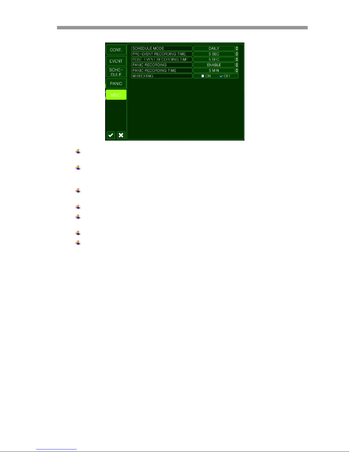
6.6.5 MISC.
SCHEDULE MODE: Either DAILY (one schedule will apply to every day of the week) or WEEKLY
(each day of the week has its own schedule).
PRE EVENT RECORDING TIME: When the DVR is not in continuous recording mode, this setting
determines the amount of footage that is always recorded before an event occurs (motion
detection, alarm input etc.)
POST EVENT RECORDING TIME: You can configure how long the system keeps event recording
after event triggered.
PANIC RECORDING: You can enable Panic recording or not.
PANIC RECORDING TIME: When PANIC RECORDING is set to Enable it determines the amount
of time. The DVR records in panic mode before reverting back to standard recording mode.
MIRRORING : You can enable/disable mirroring recording mode.
MIRRORING TYPE
ALL : All date recorded to the regular HDD will be recorded to the mirroring HDD.
EVENT : Just event data will be recorded to mirroring HDD.
SELECT CHANNEL FOR MIRRORING : You can check which channel will be recorded to
mirroring HDD.
Page 53
VT-HDOC Series
52
6.7 CONFIGURING EVENT/SENSOR
You can configure the Event/Sensor activations such as Alarm Input / Alarm Output / Buzzer Out / E-Mail /
PTZ Preset.
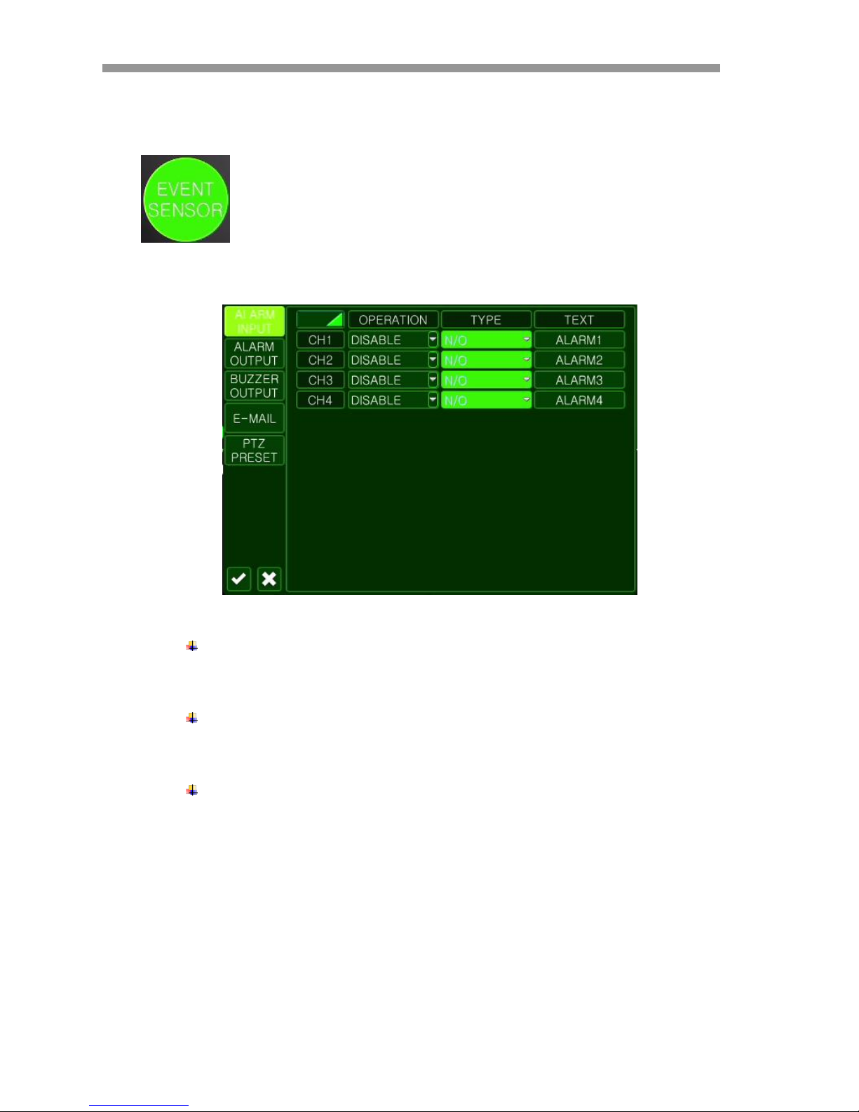
6.7.1 ALARM INPUT SETUP
You can configure Alarm input .
OPERATION : You can configure activation when Sensor is triggered.
DISABLE : Disables the alarm input.
ENABLE : Enables the alarm input.
TYPE : If the operation is enabaled ;
N/O : Normally Open
N/C : Normally Closed .
TEXT : If an event is triggered by Sensor input, you can customize the title of the alarm
channel that will be displayed.
Page 54
VT-HDOC Series
53
6.7.2 ALARM OUTPUT SETUP
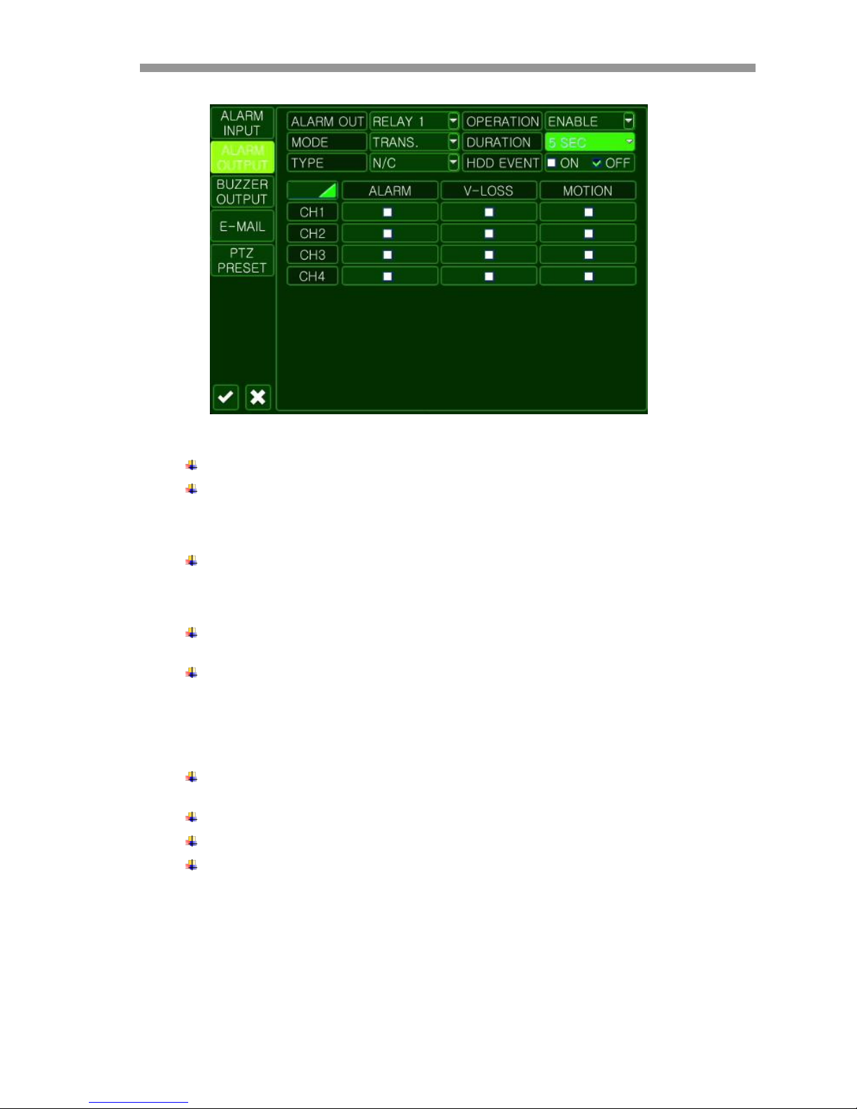
You can cofniture the activation Relay output .
ALARM OUT : Select Relay 1 for configuration
OPERATION : You can configture the output status of Relay 1.
DISABLE : Relay is disabled
ENABLE : Relay is enabled once an event is triggered.
MODE : You can configture activatoin mode of the Relay output.
TRANSPARENT : Keep the Relay output until the triggering event has stopped.
LATCHED : Keep the Relay ouput for the set duration time; see DURATION next.
DURATION : If the alarm output mode is configured as Latched, you can configure duration
time for relay output.
TYPE : Define the trasition of the signal of Alarm output
N/O(Active Low): When an event is triggered, the relay will go to ‘Close’ state from the
‘Open’ state.
N/C(Active High): When an event is triggered, the relay will go to ‘Open’ state from the
‘Close’ state.
HDD EVENT : If you select “ON”, when an HDD related Event is triggered, the relay ouput will
be started.
ALARM : When sensor input is triggered, the relay output will be started.
VIDEO LOSS : When video loss occurs, the replay output will be started.
MOTION : When motion triggered, the replay output will be started.
Page 55
VT-HDOC Series
54
6.7.3 BUZZER OUTPUT SETUP
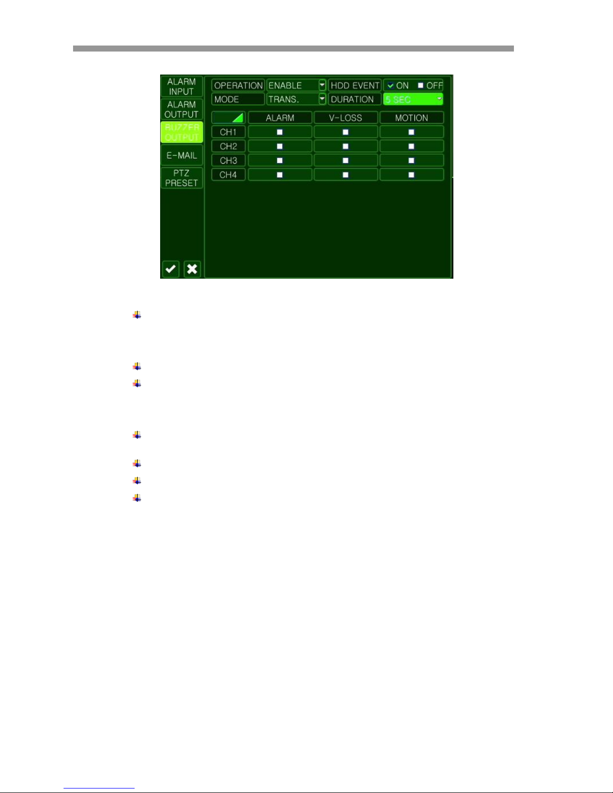
You can configure the Buzzer output when an event is triggered.
OPERATION : You can configure the output status of the Buzzer.
DISABLE : Buzzer is disabled when an event is triggered.
ENABLE : Buzzer is enabled when an event is triggered.
HDD EVENT : If HDD related event is triggered, the Buzzer output will be started.
MODE : You can configure the operation mode of Buzzer output.
TRANSPARENT : Keep the Relay output until the triggering event has stopped.
LATCHED : Keep the Buzzer ouput for the set duration time; see DURATION next.
DURATION : If the Buzzer output mode is configured as Latched, you can configure duration
time for Buzzer output.
ALARM : When a sensor input is triggered, the buzzer output will be started.
VIDEO LOSS : When video loss occurs, the buzzer output will be started.
MOTION : When motion is triggered, the buzzer output will be started.
Page 56
VT-HDOC Series
55
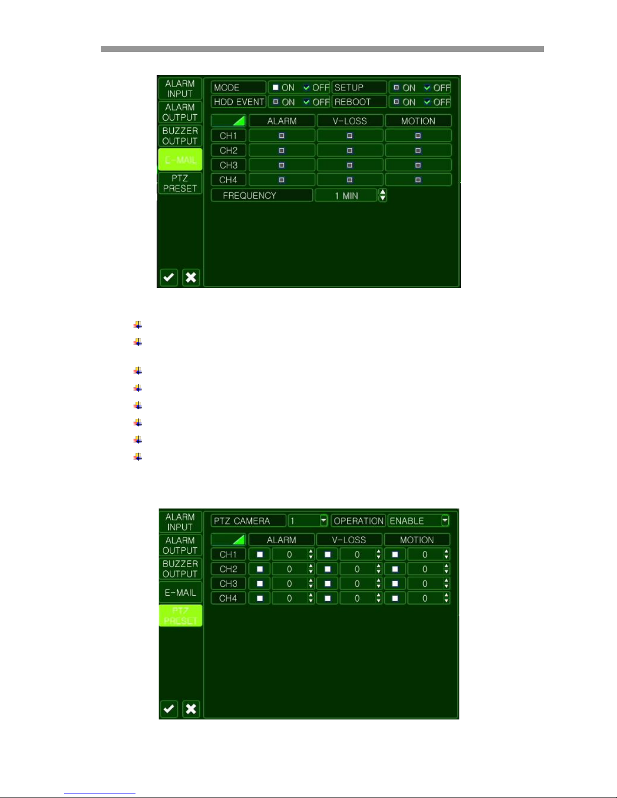
6.7.4 E-MAIL SETUP
You can configure the DVR to send E-mail notifications when an event is triggered.
NOTIFICATION : If you select “ON”, an E-mail will be sent when an event is triggered.
SETUP CHANGE : If you select “ON”, an E-mail will be sent when the menu configuration is
changed.
HDD EVENT : If you select “ON”, an E-mail will be sent when a HDD related event is triggered.
BOOT EVENT : If you select “ON”, an E-mail will be sent when the DVR boots up .
ALARM : An E-mail will be sent when the sensor is triggered.
VIDEO LOSS :An Email will be sent when video loss occurs.
MOTION : An Email will be sent when motion has been triggered.
FREQUENCY : You can configure the E-Mail notification period.
6.7.5 PTZ PRESET SETUP
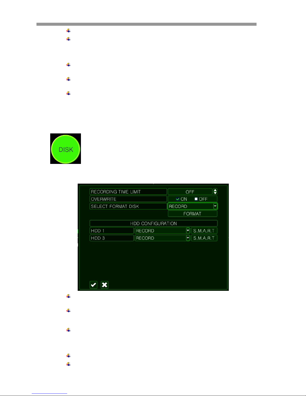
You can configure the PTZ preset feature when events are triggered.
Page 57
VT-HDOC Series
56
PTZ CAMERA: Select the PTZ camera for the following configuration to be applied.
OPERATION : Can be set to Enable/Disable
DISABLE : Disables this feature
ENABLE : Enables this feature.
ALARM PRESET : When an alarm Sensor is triggered, you can configure what preset the PTZ will
go to by seletcing the preset number in the dropdown box.
V-LOSS PRESET : When video loss occurs, you can configure what preset the PTZ will go to by
seletcing the preset number in the dropdown box.
MOTION PRESET : When motion is triggered, you can configure what preset the PTZ will go to
by seletcing the preset number in the dropdown box.
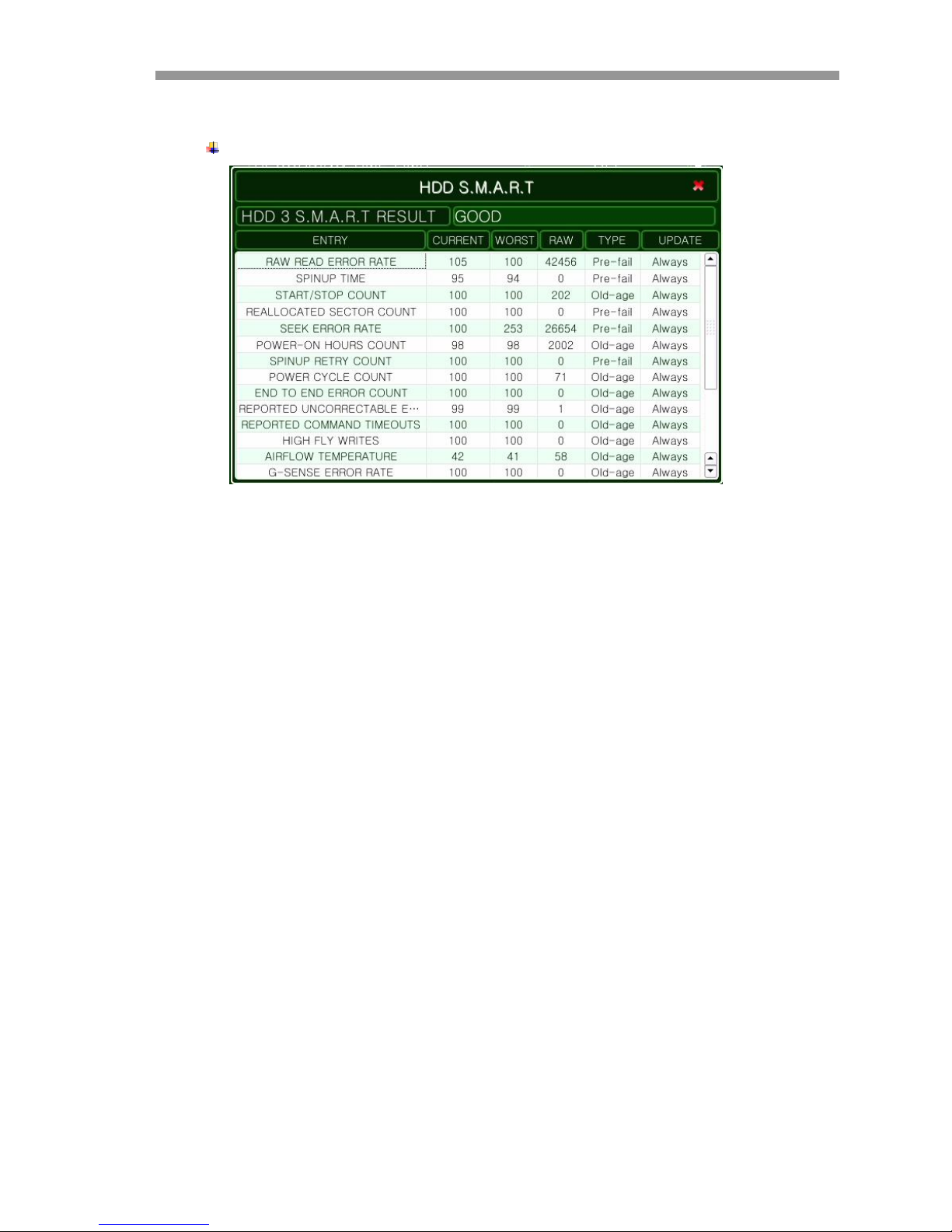
6.8 CONFIGURING DISK
You can configure DISK operation, such as Recording Time Limit / Overwrite / HDD Type / Format / HDD
Configuration.
RECORDING TIME LIMIT : You can limit the amount of data that will be recorded on the hard
drive by length of time (12hr – 2 month).
OVERWRITE : IF you select “ON”, the overwrite mode will be activated. When set to ON,
the DVR will start overwriting the earliest recorded footage once the hard drive
becomes full.
HDD TYPE : You can select HDD when you try to format.
RECORD : You select HDD of record to format at HDD configuration.
MIRRORING : You select HDD of mirroring to format at HDD configuration.
FORMAT : You can format the HDDs.
HDD CONFIGURATION : You can view HDD’s connected to the DVR and the corresponding
S.M.A.R.T. data.
Page 58
VT-HDOC Series
57
RECORD : You can select HDD as record HDD.
MIRRORING : You can select HDD as mirroring HDD.
S.M.A.R.T : You can view S.M.A.R.T information of HDD.
GOOD : It shows current HDD condition is good.
BAD : It shows current HDD condition is bad.
Page 59

VT-HDOC Series
58
7. REMOTE
7.1 WEB SERVER
The DVR prepares the web server internally. This server consists of two services. One is for the remote
configuration of the DVR setup and the other is for the client viewer (based on Active-X).
Using the remote configuration, you can configure all of the features of the DVR. Using the WebViewer, you
can view live video, search, and PTZ controls.
The table below shows the recommended PC specifications:
[Minimum & Recommended Specification of PC]
Minimum
Recommended
Operating System
Windows XP
Windows 7
CPU
Core2Duo @2.53GHz or Equivalent
Core i5 @3.3GHz or Higher
Memory
1 GB
2 GB
Video Card Memory
512MB
512MB
HDD Capacity
50MB
2GB
VGA Resolution
1280x1024x16
1920x1080x32
Direct-X
DirectX 7.0
DirectX 9.0c
Network
Ethernet 10/100B-TX
Page 60
VT-HDOC Series
59
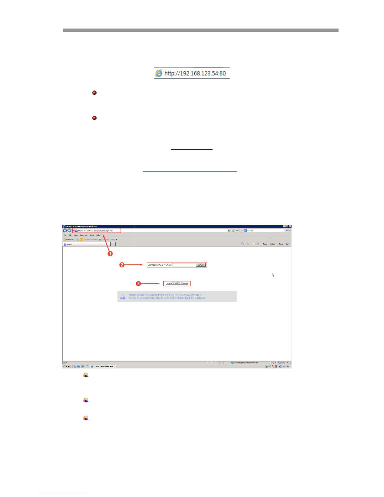
7.1.1 CONNECT TO WEB SERVER
Enter the IP address of DVR into the ULR bar (see picture below)
LOCAL NETWORK ACCESS: To find the IP address of the DVR, go to the ‘INFO’ section
under the SYSTEM/MANAGEMENT of the DVR’s menu. If you are on the same network as
the DVR, you can use the DVR’s IP address to access it.
REMOTE NETWORK ACCESS: To access the DVR from a remote network, you need to use
the WAN IP address of the network the DVR is connected to. (Sometimes this address is
referred to as the LIVE, PUBLIC, or OUTSIDE IP). In order to view your DVR remotely you
MUST port forward BOTH the DVR PORT and the WEB SERVER PORT. To find the DVR and
Web Server ports, go to the NETWORK SETUP page.
If you need assistance with port forwarding, please visit our website and review our
tutorial videos: http://vitekcctv.com/videotutorials.asp. If you need further assistance,
please reference your router’s manual or contact your Network Administrator/IT
Professional. If your router supports the ‘uPNP’ feature, there is no need to manually
configure ‘Port Forwarding’ because the DVR supports the ‘Auto Port Forwarding’ function
using the ‘uPNP’ protocol.
[The initial screen of Web Server]
1: Enter the IP address of your DVR. If you don’t use the default Web Server Port number (80),
you will need to add the port number following the IP address. For example, if the Web Server
Port was set to 8181, you would type the following: http://192.168.123.63:8181
2: Input the adminstrator’s password. Only an admistrator can log in for remote DVR
configuration. Clikcing the ‘LOGIN’ button will guide you to the DVR configuration pages.
3: ActiveX based Web Viewer: Clicking this link will execute the ‘WebViewer’ or initiate the
installation of the ActiveX plugin.
Page 61
VT-HDOC Series
60
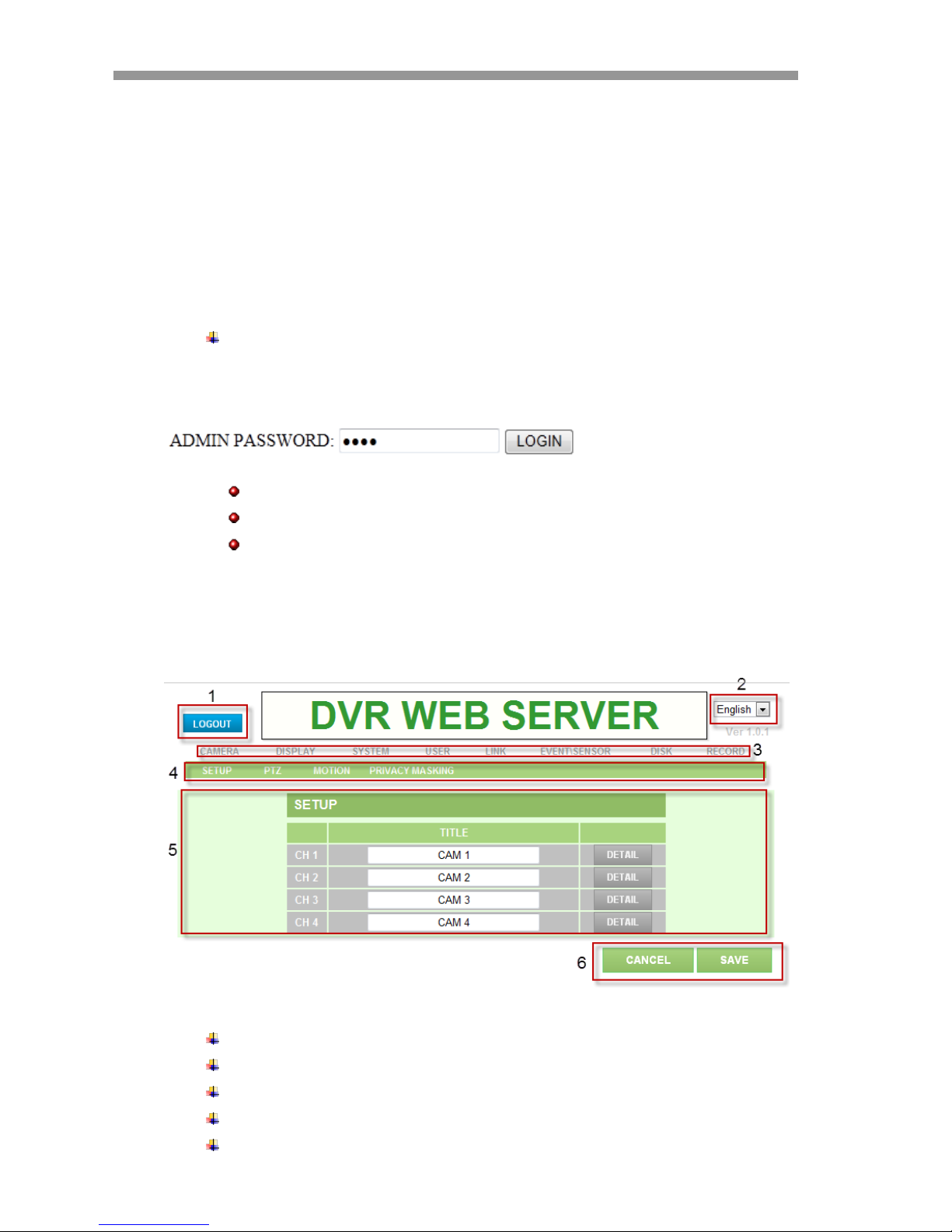
7.1.2 WEB CONFIGURATION PAGE
In the web configuration page, you can set the DVR operations remotely.
Tested Web Browser List
Microsoft Internet Explorer○
R
Mozilla Firefox○
R
Google Chrome Browser○
R
Opera Browser○
R
Apple Safari○
R
Features
Configuring the DVR setup remotely
After entering the ADMIN password and clicking ‘LOGIN’, you can navigate to the page where you can
configure the setup menu of DVR.
NOTE: Default Password for ADMIN: 1234
NOTE: Only the ADMIN account can access the menu configuration pages.
NOTE: When the page has been idle for more than 5 minutes, it will be logged out
automatically.
7.1.2.1 Initial Page of Web Configuration
1: Log out from the configuration page
2: Version number of this web configuration
3: Top menu of DVR
4: Sub menu of DVR
5: Setting or Information section
Page 62

VT-HDOC Series
61
6: Cancling or applying the modification
CANCEL : Ignore any modification and the settings are restored to the previous setting
SAVE: the modified settings are applied to DVR and saved
In order to apply or save, you should click the ‘SAVE’ button. Otherwise all the changes will
be lost.
For more details of the DVR configuration, please refer to the ‘5.HOW TO CONFIGURE’ section of this
manual. Clicking any of the following links will guide you to the proper section which explains each setup.
CAMERA
DISPLAY
SYSTEM
USER
NETWORK
EVENT/SENSOR
DISK
RECORD
Live View, Search, Playback & Copy functions are not supported from the web server. To
user these, please use the ‘Web Viewer’ instead.
7.1.3 WEB VIEWER (Active-X)
Through the ‘Web Viewer’, you can see the live, search and playback of recordings in the DVR and copy the
recordings from the DVR.
Tested Web Browser
Miscrosoft Internet Explorer○
R
Mozilla Firefox○
R
Google Chrome Browswer○
R
Features
The ‘Web Viewer’ is based on the ActiveX
Monitor live, preview videos from the DVR.
Search & Playback of the recorded video in the DVR
Copy the recorded data from the DVR to the PC remotely
PTZ camera control
7.1.3.1 Installation and Execution
[Microsoft IE]
Click the ‘ActiveX WEB Viewer’ to initiate the installation of the ‘Web Viewer’ (if not installed previously). If the
‘Web Viewer’ is installed already in your IE browser, clicking ‘ActiveX WEB Viewer’ will launch the WEB
Viewer.
Page 63
VT-HDOC Series
62
NOTE: To install properly, connect your PC to the internet.
NOTE: ‘Web Viewer’ is certificated with the name ‘NEOXENTEC SYSTEMS CO.LTD’, who
designs the application.
NOTE: The first execution of ‘Web Viewer’ will install the application first.
NOTE: If a new updated version of ‘Web Viewer’ is found, updating starts automatically
before execution.
[Google Chrome]
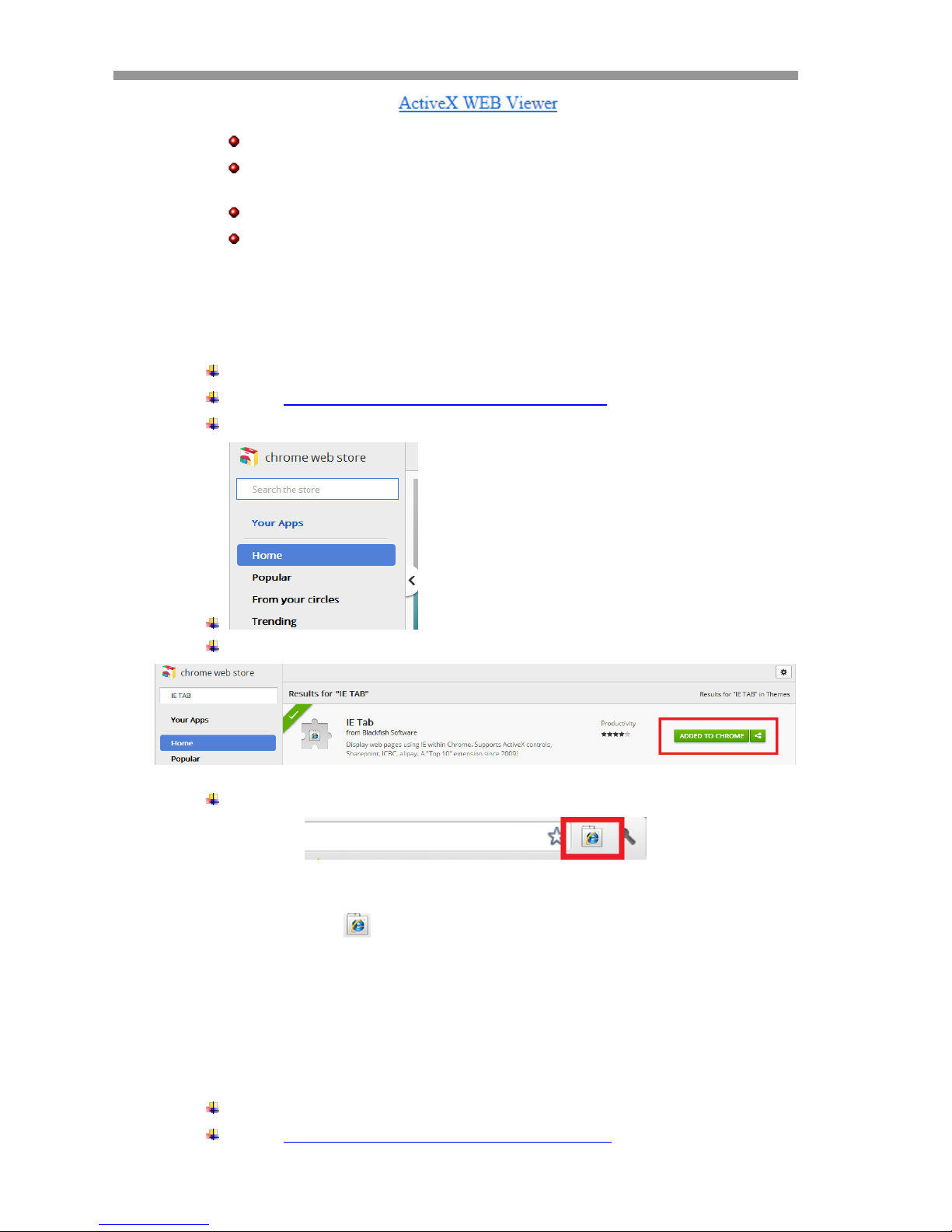
In order to execute the ActiveX plugin, you have to install the ‘IE TAB’ from the Google web store. Please
see the following steps:
Execute the Chrome browser
Goto the https://chrome.google.com/webstore/category/home
Enter the word ‘IE TAB’ into the ‘Search the store’ box and press enter.
‘Searching’ shows the results such as below.
Click the ‘ADD TO CHROME’ and then you can see the IE symbol on the right side of URL Bar
There are two ways to execute the ‘Web Viewer’ from the Chrome.
1. Clike the ICON( ) on the right side of URL bar. It opens new URL bar to get the URL.
Entering the required IP address of DVR will connect the web server.
2. Just entering the IP address of DVR into the URL bar of Chrome and press enter
[Mozilla Firefox]
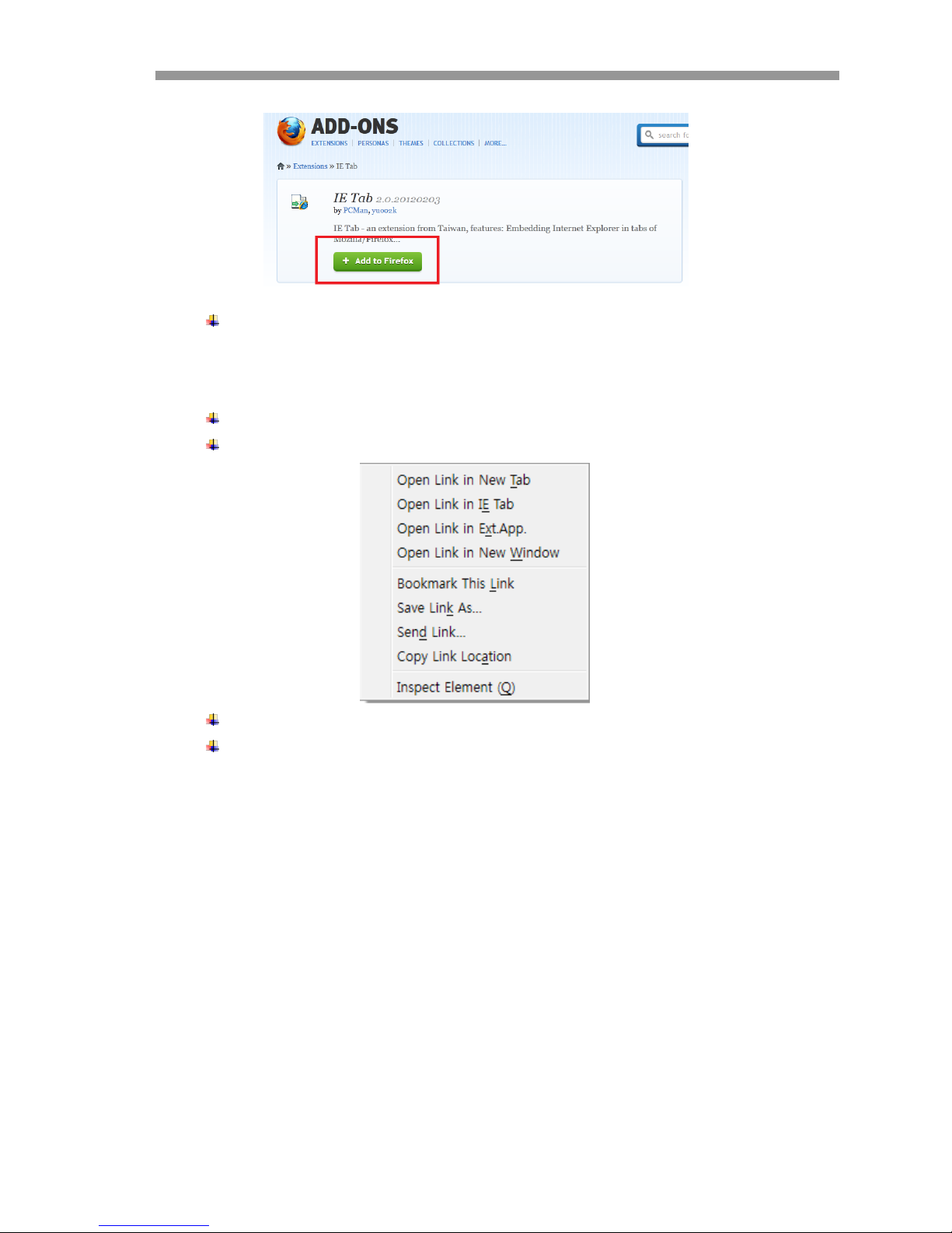
In order to execute the ActiveX plugin, you have to install the ‘IE TAB’ from the add-on page of Firefox.
Please see the following steps:
Execute the FireFox browser
Goto the https://addons.mozilla.org/en-US/firefox/addon/ie-tab. And then the following page
Page 64
VT-HDOC Series
63
will show the way to install the ‘IE TAB’.
Click the ‘Add to Firefox’ will enable supporting Active-X plugin.
How to execute the ‘Web Viewer’ from the Firefox
Enter the IP of DVR into the URL bar of Firefox.
Right-click the link ‘AcitveX WEB Viewer’ will show the pop-up menu such as below.
Select the ‘Open Link in IE TAB’.
First execution will install the ActiveX plug-in. And the application will be executed if installed
already.
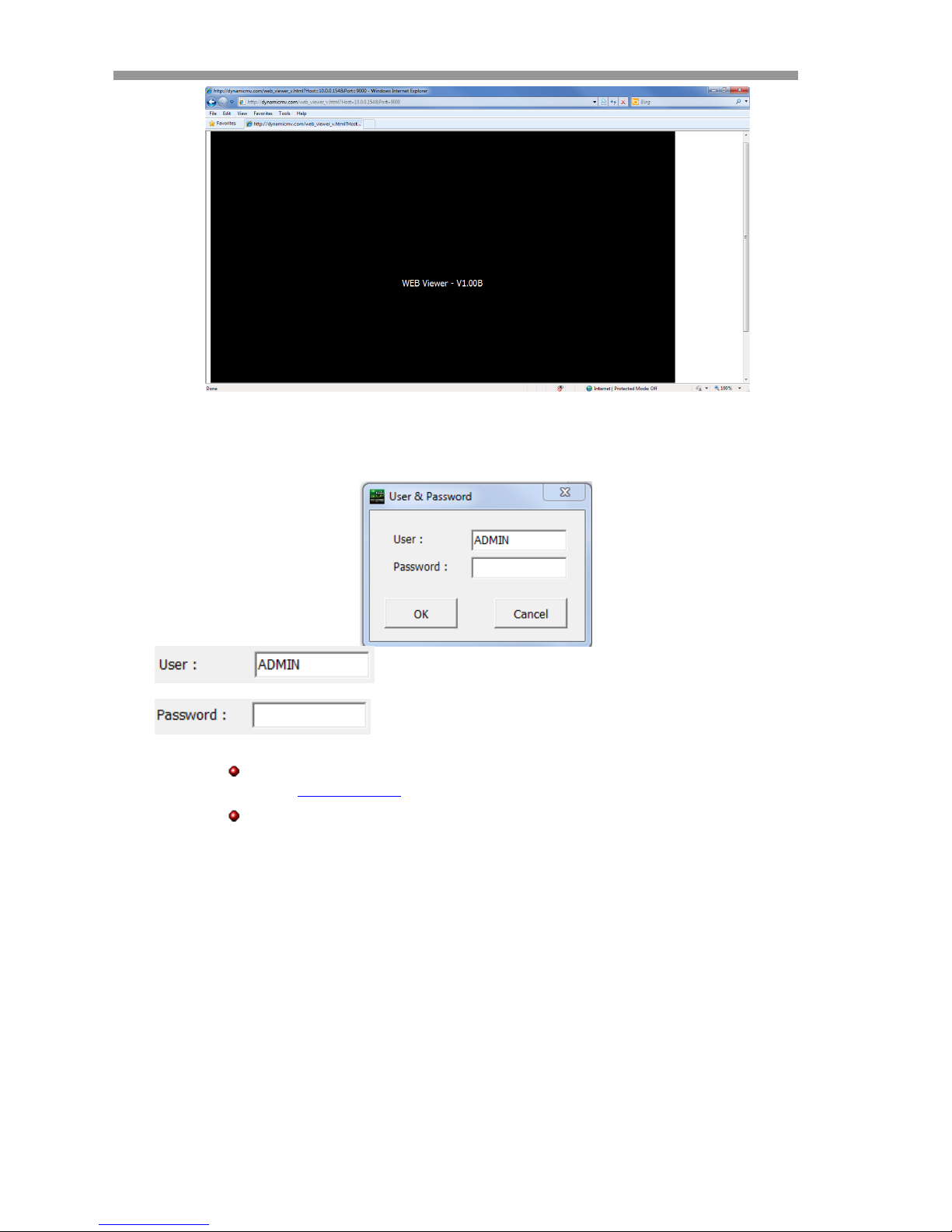
7.1.3.2 Initial Screen of Web Viewer
Executing the ‘Web Viewer’ opens the application in a separate window from the web browser and
displays the login window (see images below).
Page 65
VT-HDOC Series
64
.
7.1.3.3 Log In
: Enter the USER name registered in the DVR
: Enter the Password for the selected user.
The user authority functions (live view, search & playback, PTZ control, etc.), are controlled
by the USER AUTHORITY settings in the DVR menu.
USER ID and Password are case-sensitive.
Page 66
VT-HDOC Series
65
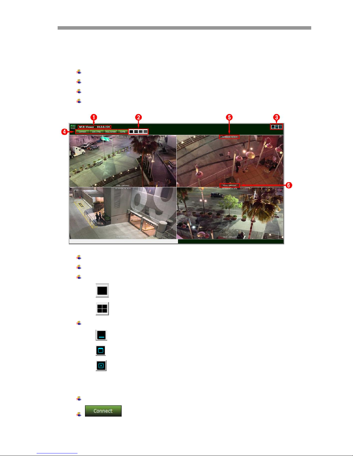
7.1.3.4 Live Preview
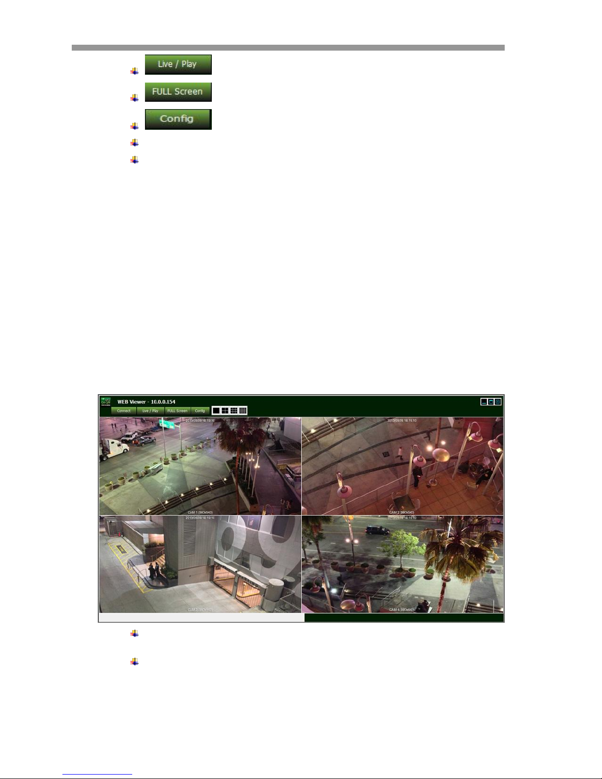
After logging in, the live preview screen will be shown (see below).
Features
User log-in/out feature (RECONNECT)
Monitoring live view
Snapshot and save as JPEG
Control the resolution and quality of video stream
The colored rectangle around video shows the currently selected camera
1: IP of DVR connected remotely
2: display split mode selection
: Single camera view
: Quad split view
3: WEB Viewer Minimize/Maximize/Close
: Minimize the window
: Maximize the window
: Exit the ‘Web Viewer’
4: Reconnect/Live&Search/Full Screen/Config
: Log out and Reconnect
Page 67
VT-HDOC Series
66
: Switching between the live and search & playback
: Full screen video view. Press ‘ESC’ to return to the window
: Set the default save location for JPEG/AVI
5: Date & Time of Camera transferred from the DVR
6 : Channel Title and the resolution of the transferred video
Resolution Steps for HD SDI DVR:
720p Camera: 1280x720 / 1280x360 / 640x360 / 640x180 / 320x180
1080p Camera : 1920x1080 / 1920x540 / 960x540 / 960x270 / 480x270
Default Resolution: 720p Camera: 640x360, 1080p Camera: 960x540
7.1.3.5 JPEG Snapshot/ PTZ control / Video Configuration /Live Audio
In the Web Viewer, you can save a live image as a JPEG file, control a PTZ camera, and hear the audio from
the DVR. You can also configure the transferred video stream coming from the DVR.
Right-click on the video window shows the pop-up menu (see below).
Save to JPEG File: Save the current view of the selected channel with the colored border to the
PC as a JPEG file.
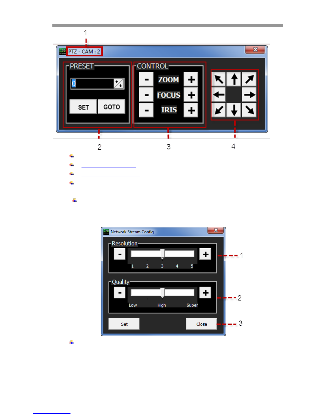
PTZ Control : Open the PTZ control panel, which controls the PTZ camera of the selected
channel.
Page 68
VT-HDOC Series
67
1: Camera Channel number which is currently selected.
2: PRESET OPERATION OF PTZ
3: ZOOM/FOCUS/IRIS CONTROL
4: DIRECTION CONTROL (PAN & TILT)
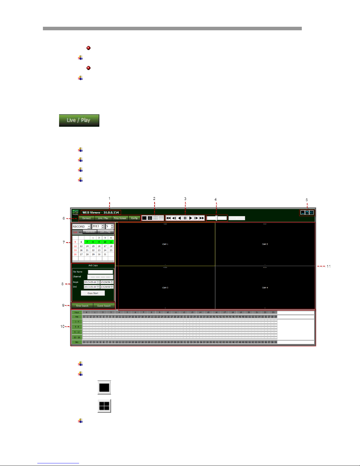
Network Stream Config : Open the ‘Network Stream Config’ panel where you can choose the
resolution and the quality for the transferred video. The changes will affect all channels.
1: Resolution selection (5 levels)
HD SDI DVR
Level 1: 720p : 320x180 / 1080p : 480x270
Level 2: 720p : 640x180 / 1080p : 960x270
Level 3: 720p : 640x360 / 1080p : 960x540
Level 4: 720p : 1280x360 / 1080p : 1920x540
Page 69
VT-HDOC Series
68
Level 5: 720p : 1280x720 / 1080p : 1920x1080
Default Value: 640x360 for 720p, 960x540 for 1080p
2: Modify the quality of video (5 steps): LOW,NORAL,HIGH,BEST,SUPER
Default Quality: ‘HIGH’
3: Apply the modification (SET) and close the panel
7.1.3.6 Search & Playback
Toggles the Live & Playback window
Features
User log-in/out feature (CONNECT)
Toggle between the live and the search & playback
Search & Playback
Copy the recordings from the DVR to the PC remotely
1: Show the IP address of DVR currently connected
2: Split mode selection.
: Single camera view
: Quad split view
3: Playback speed control
Page 70
VT-HDOC Series
69
: Reverse Fast
: Reverse Slow
: Reverse Normal Speed
: Pause
: Forward Normal Speed
: Forward Slow
: Forward Fast
Steps for fast playback : x2, x4, x8, x16,x30, x60, x120
Steps for slow playback : 1/2, 1/4, 1/8, 1/16, 1/30, 1/60, 1/120
4: Fast Playback Speed & Direction Control Bar
Mouse wheel up: fast forward
Mouse wheel down: fast reverse
Center click: normal speed playback
Click on the right half of bar : fast forward
Click on the left half of bar: fast reverse
7 level speed control for each direction
5: View window control
: Minimize the window
: Maximize the window
: Exit the ‘Web Viewer’
6: Reconnect/Live&Search/Full Screen
: Log out and Reconnect
: Switching between the live preview and the search & playback
: Full screen video view. Press ‘ESC’ to return to the standard window
7: Calender Panel: Select between RECORD (main HDD) and MIRROR (if setup) Year and Month.
The green color indicates that recorded data exists. Clicking the date will tigger the search of
the selected day. The search results are displayed on the time selection table (10).
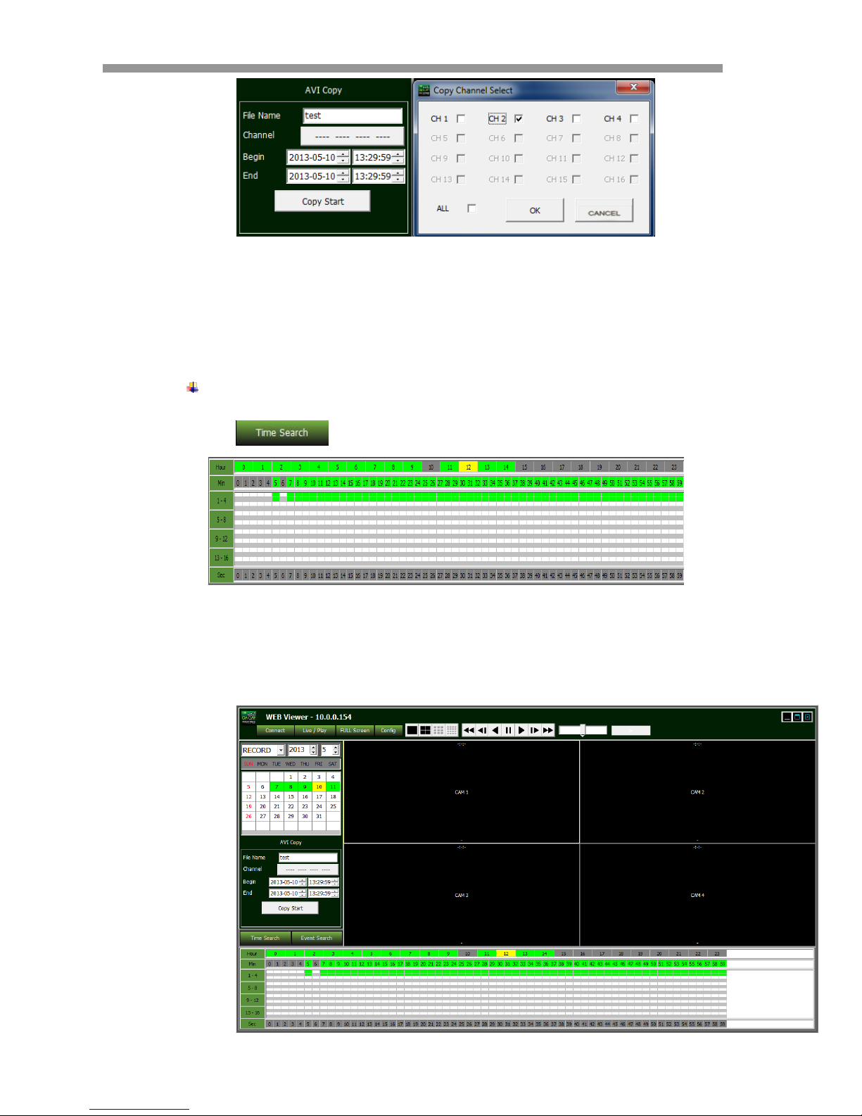
8 : Copy the recorded video from the DVR to the PC
File Name: Name of the AVI file being saved.
Channel: Choose the desired channel(s)
Page 71
VT-HDOC Series
70
Begin: The start time of the recording
End: The end time of the recording
Copy Start: executing the copy operation
9 : Choose search type between ‘TIME’ and ‘EVENT’. The time selection table ‘10’ in the
above picutre is used for one of the two search type’s
: changes the search mode to ‘Time Search’.
Yellow colored cell indicates the currently selected hour and minute.
Green colored cell means that there is recorded data from the continuous recording mode.
Red colored cell means that there is event recording data.
Double-clicking on the cell in the minutes bar will start the playback from the selected
time.
Page 72
VT-HDOC Series
71
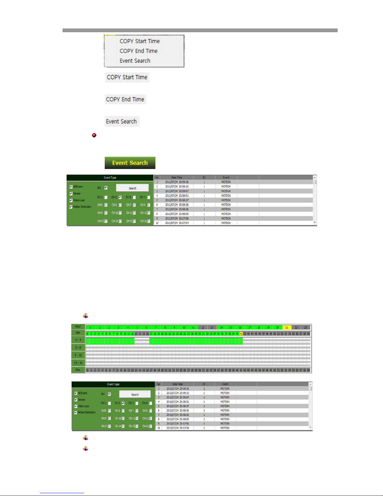
: Right-click the minute bar to show the pop-up menu
: Takes the ‘COPY START TIME’ from the selected time cell and puts it
into the ‘Begin’ of the COPY control panel.
: Takes the ‘COPY END TIME’ from the selected time cell and puts it
into the ‘End’ of the COPY control panel.
: Takes the time for ‘EVENT SEARCH start time’.
Clicking on the ‘second’ bar will move the second of playback video to the selected second.
This is only available while playback is on-going.
: Changes the search mode to ‘EVENT Search’.
Event Type(Search Condition)
All: For all recording events
Sensor: sensor input event
Video Loss: lost video event
Motion Detection: all motion activated recording
CH ALL: Searching for all channels
CH1/CH2/CH3/CH4: choosing the channel to be searched
Search: execute the event search again
10: Time selection & recording indication table / Event search result window
11: display the playback video as a result of searching.
12: show the current playback mode, speed and direction.
Page 73
VT-HDOC Series
72
.
7.2 DDNS SERVER
You can get Domain Name Service through the DDNS server.
7.2.1 HOW TO REGISTER
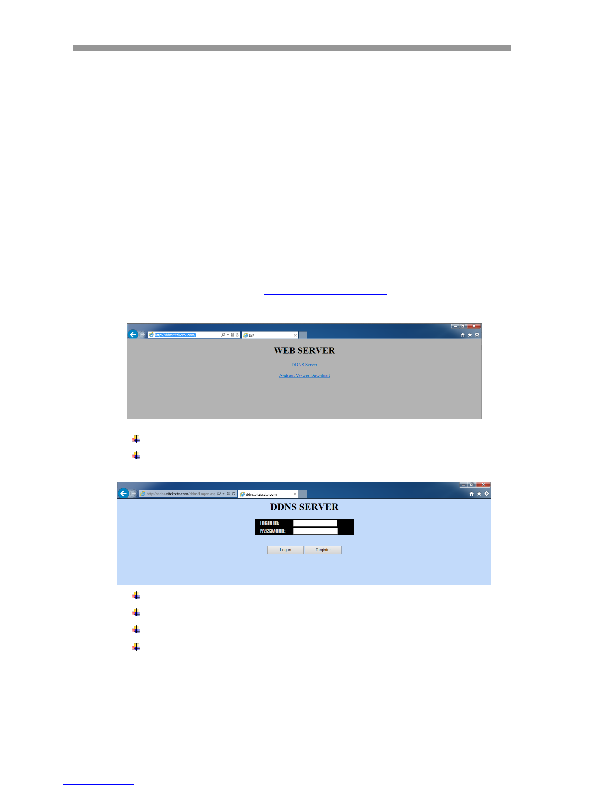
Input the following URL into your browser: http://ddns.vitekcctv.com
ANDROID VIEWER: You can download Android Viewer ( iPocketViewer)
DDNS SERVER: Press the DDNS Server link to go to the DDNS server page.
LOGIN ID : Input USER ID.
PASSWORD : Input Password.
Logon : Press Log-in button to log-in
Register : You can create a user account.
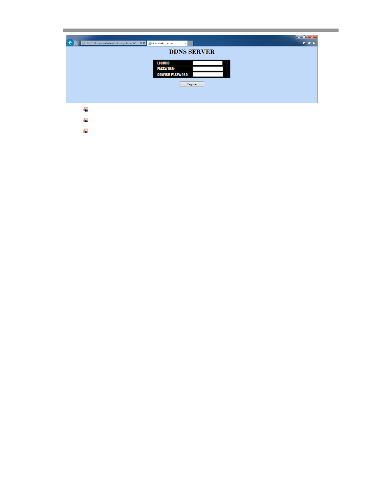
7.2.2 REGISTER
You can create a user account by selecting the register button.
Page 74
VT-HDOC Series
73
LOGIN ID : Create an ID.
PASSWORD : Create a Password..
CONFIRM PASSWORD: Input the password again to confirm the password.
Page 75
VT-HDOC Series
74
7.2.3 Input DVR information.
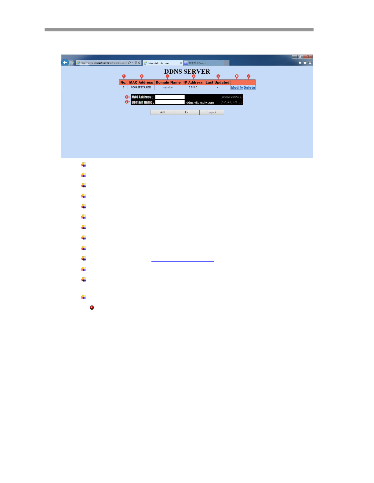
You need to register domain name to get the service and input MAC address into DDNS server.
1 : List number of registered DVR
2 : Mac address of registered DVR (under system info in DVR)
3 : Domain name of registered DVR.
4 : IP address of registered DVR.
5 : Last time that DVR sent the info to the DDNS server.
6 : Update of Last Update
7 : Delete of Domain name registered in the DDNS server.
8 : Input the Mac Address of the DVR that you want to register to the DDNS server.
9 : Input the Domain name of the DVR that you want to register to the DDNS server.
The Domain name type is: http://ddns.vitekcctv.com
ADD : You can register the DVR to the DDNS server by selecting the ADD button.
LIST : A list of DVR’s (on your current IP Public IP Address) that are registered with the DDNS
server will be displayed.
LOGOUT : User can log out
Note: It will take approximately 10 to 15 minutes to confirm the DDNS registration.
Page 76
VT-HDOC Series
75
7.3 DVR MANAGER
The DVR MANAGER is a ‘Remote Client DVR Viewer’ The program allows the user to monitor live video,
Search & Playback, and Download Recorded Video from the DVR (Remote COPY).
[Minimum & Recommended Specification of PC]
Minimum
Recommended
Operating System
Windows XP
Windows 7
CPU
Core2Duo @2.53GHz or Equivalent
Core i5 @3.3GHz or Higher
Memory
1 GB
2 GB
Video Card Memory
512MB
512MB
HDD Capacity
50MB
2GB
VGA Resolution
1280x1024x16
1920x1080x32
Direct-X
DirectX 7.0
DirectX 9.0c
Network
Ethernet 10/100B-TX
7.3.1 INSTALLATION
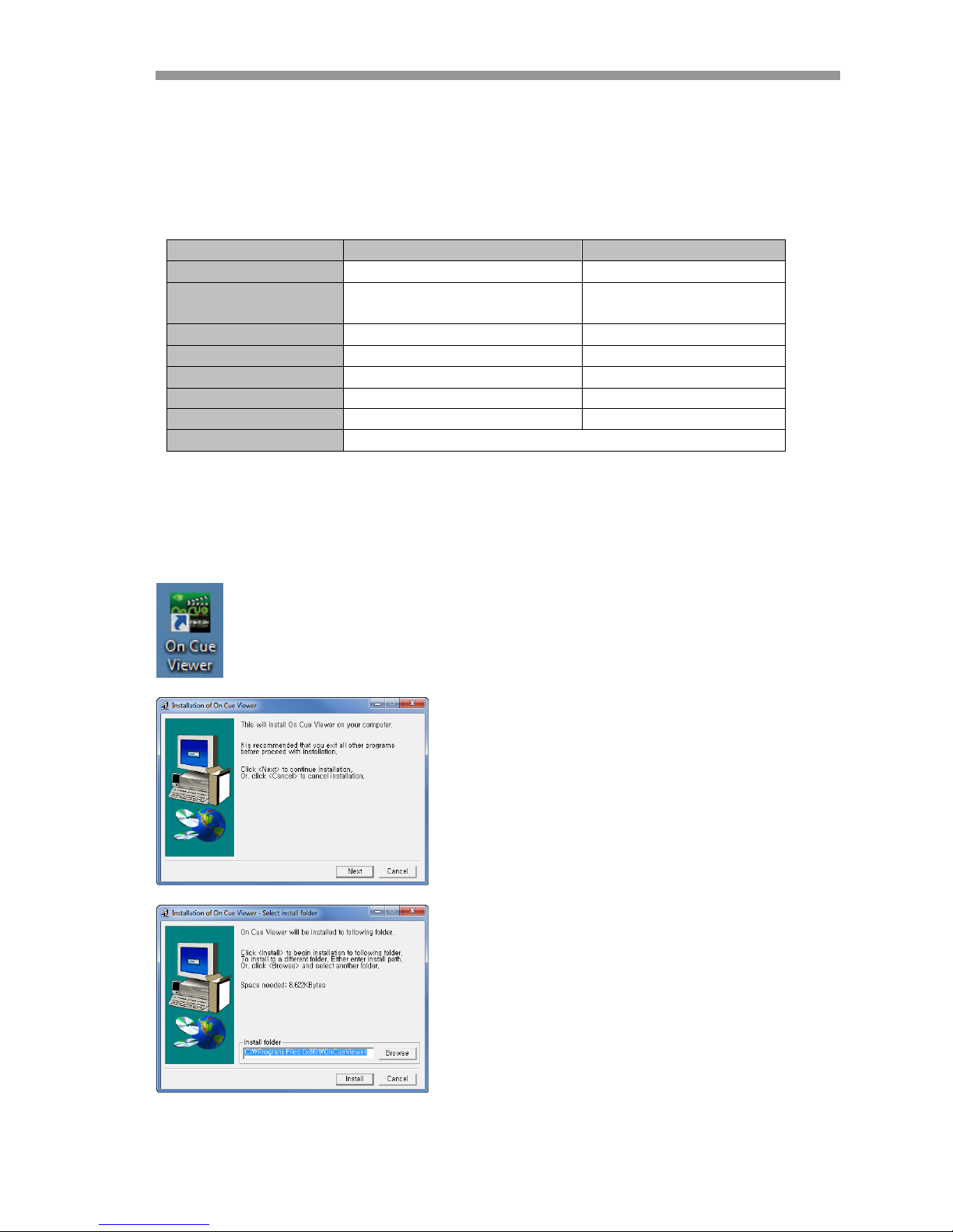
You can install the ‘DVR Manager’ using the ‘setup’ program which is provided on the CD.
Executing the ‘DvrManager_setup.exe’ in the On Cue Viewer folder will initiate the installation.
Setup program of On Cue Viewer
: Introduction of Setup
: Specify the folder location for installation.
Page 77
VT-HDOC Series
76
: Complete Message Window
7.3.2 EXECUTION
After installing the program successfully, a shortcut named ‘OnCue Viewer’ will be created. Clicking
this icon executes the OnCue Viewer.
: Shortcut and icon of DVR Manager
7.3.3 LIVE VIDEO MONITORING
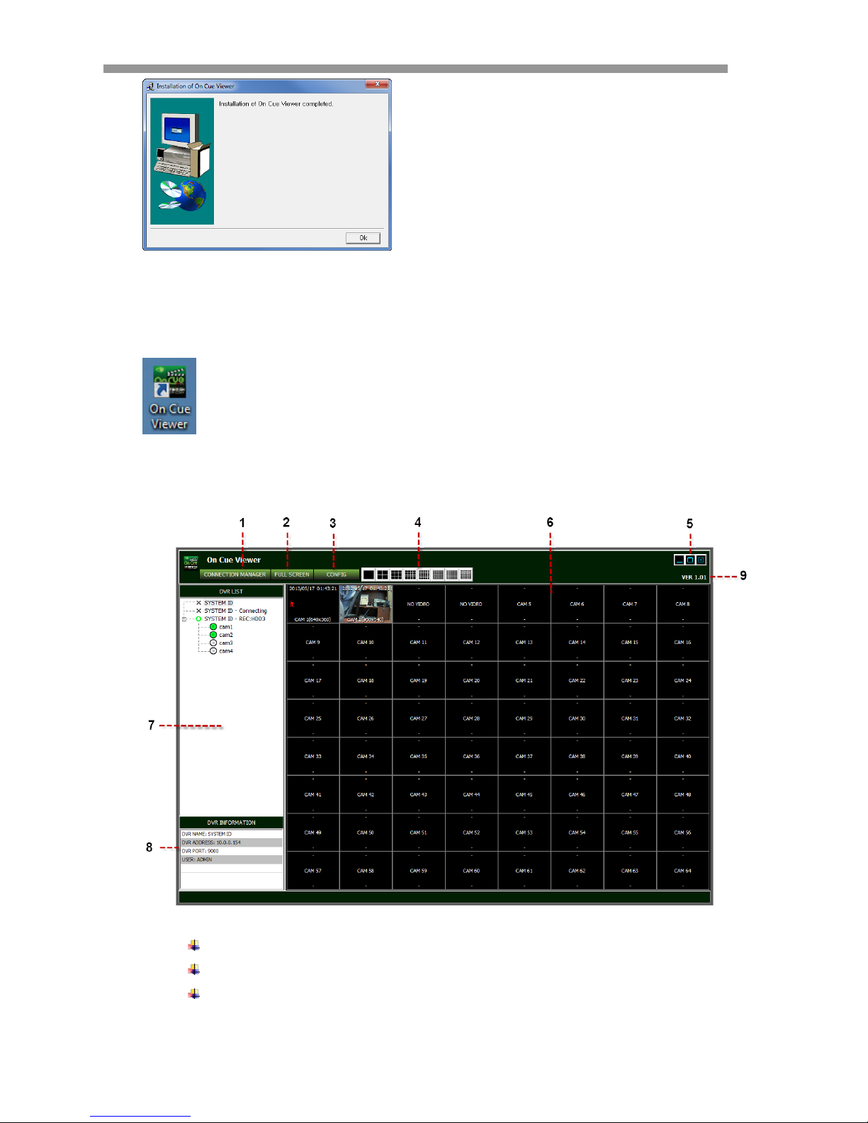
The initial window of OnCue Viewer is composed of the picture below.
1 : CONNECTION MANAGER: for registering or deleting the DVR to/from the DVR List.
2 :FULL SCREEN : Fill and fit only the video windows into the PC monitor.
3 :CONFIG : Saves the DVR Manager configuration
Page 78
VT-HDOC Series
77
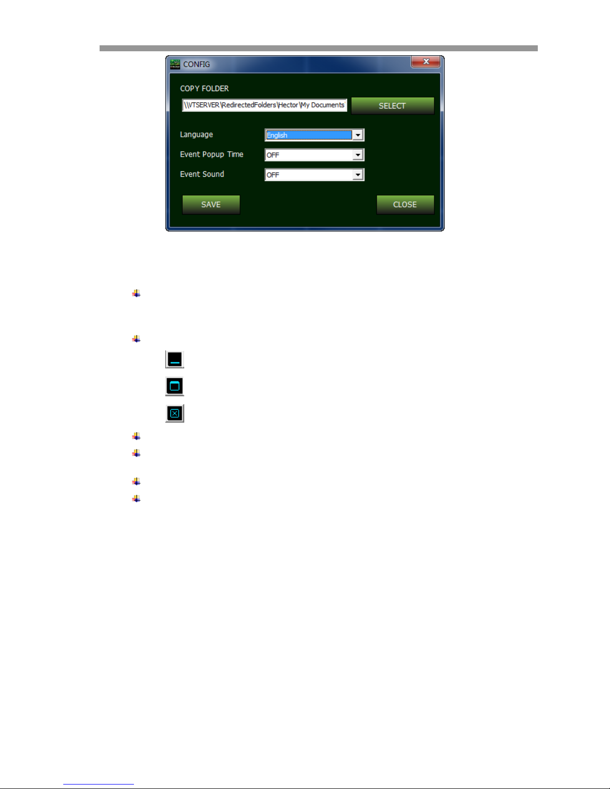
FOLDER SELECT: Choose or make the folder for the data to be copied to.
SAVE: Apply and save the current modification.
CLOSE: exit the ‘Config’ pop-up.
4 : SPLIT MODE SELECTION: choose the number of cameras which will be shown in the live
preview window.
1 / 4 / 9 / 16 / 25 / 36 / 49 / 64
5 : Minimize/Maximize/Close DVR Manager
: Minimize the window
: Maximize the window
: Exit the ‘DVR Manager
6 : Live View Window : show the live video of the connected DVR.
7 : DVR List Window : list the registered DVRs and indicate the connection status. When the
DVR is linked, the cameras connected on that DVR are listed under the DVR.
8 : DVR Information : Shows information of the DVR selected.
9 :Version: the version number of the DVR Manager
7.3.4 CONNECTION MANAGER
Register, remove and edit DVRs in the DVR list.
Page 79
VT-HDOC Series
78
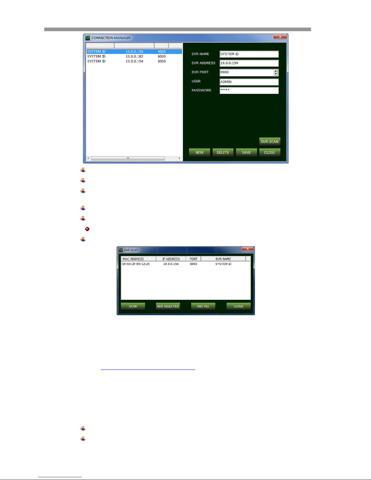
DVR Name : The name which you give to the DVR
DVR Address : specify the IP address of the DVR
DVR Port : Input the DVR Port of the DVR. The value should be the same as the one specifed
in the DVR’s menu.
USER : user ID to be used.
PASSWORD : password for the selected user.
User name and password are case-sensitive.
DVR SCAN: scan the local network and show the detected DVRs in the list.
MAC Address :shows the MAC addresses of detected DVRs
IP Address: shows the IP addresses of detected DVRs
PORT : shows the DVR PORT numbers of the detected DVRs
DVR Name: show the DVR name. This is the same as the ‘SYSTEM NAME’ under the
‘MANAGEMENT’ page of ‘SYSTEM’ menu.
Re-scan: executes scanning of the LAN again.
Add : register the selected DVR into the DVR list.
Add All : register all the scanned DVRs into the DVR list.
Close: Close the DVR SCAN window.
Add: add new DVR into the DVR list.
Edit : edit the connection information of the selected DVR.
Page 80
VT-HDOC Series
79
Remove : remove the selected DVR from the DVR list.
Close : close the CONNECTION MANANGER
7.3.5 LIVE VIDEO WINDOW
Live camera video are monitored in this window.
Features of the LIVE VIDEO WINDOW
Montioring live camera video
Swap the position of two cameras
Snapshot and save it into the PC as a JPEG file.
PAN/TILT Control remotely
Configure the quality and resolution of the transferred video.(ADMIN account only)
Live audio from DVR
Digital Zoom In
7.3.5.1 Monitoring live video stream
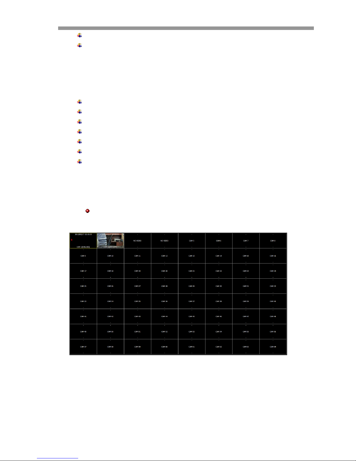
Live videos from multiple DVRs are displayed in the ‘LIVE VIDEO WINDOW’. You can configure
the number of cameras to be shown by the ‘SPLIT MODE SELECTION’ button.
Double click to change the split mode to the single channel full scale view and one more
double click from the single channel view recalls the previous split mode.
7.3.5.2 Swap Camera Position
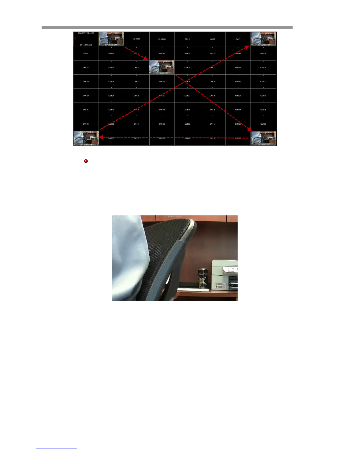
You can swap the display location of selected cameras by dragging and dropping.
Page 81
VT-HDOC Series
80
The swapped camera positions will go back to the original locations in the event the DVR
manager is restarted or the connection is re-established.
7.3.5.3 Digital Zoom in Live View
Area selection by right click of mouse dragging on the desired channel will activate the digital zoom for the
specified area.
And any clicking turns off the digital zoom.
7.3.5.4 JPEG Snapshot/ PTZ control / Video Configuration /Live Audio
You can save live video as JPEG file, control the PTZ of camera, hear the audio from the DVR, and you can
configure the live video directly from the viewer.
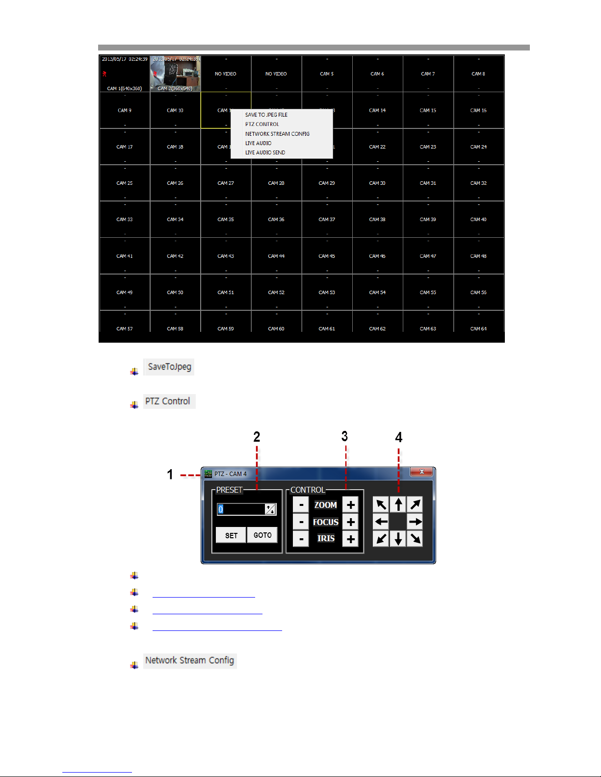
Right-click on the video window to bring up the pop-up menu (see below).
Page 82
VT-HDOC Series
81
: Save the current image (the selected channel with the colored border) to the
PC as a JPEG file.
: Open the PTZ control panel, which controls the PTZ camera of the selected
channel.
1: Camera Channel number which is currently selected.
2: PRESET OPERATION OF PTZ
3: ZOOM/FOCUS/IRIS CONTROL
4: DIRECTION CONTROL (PAN & TILT)
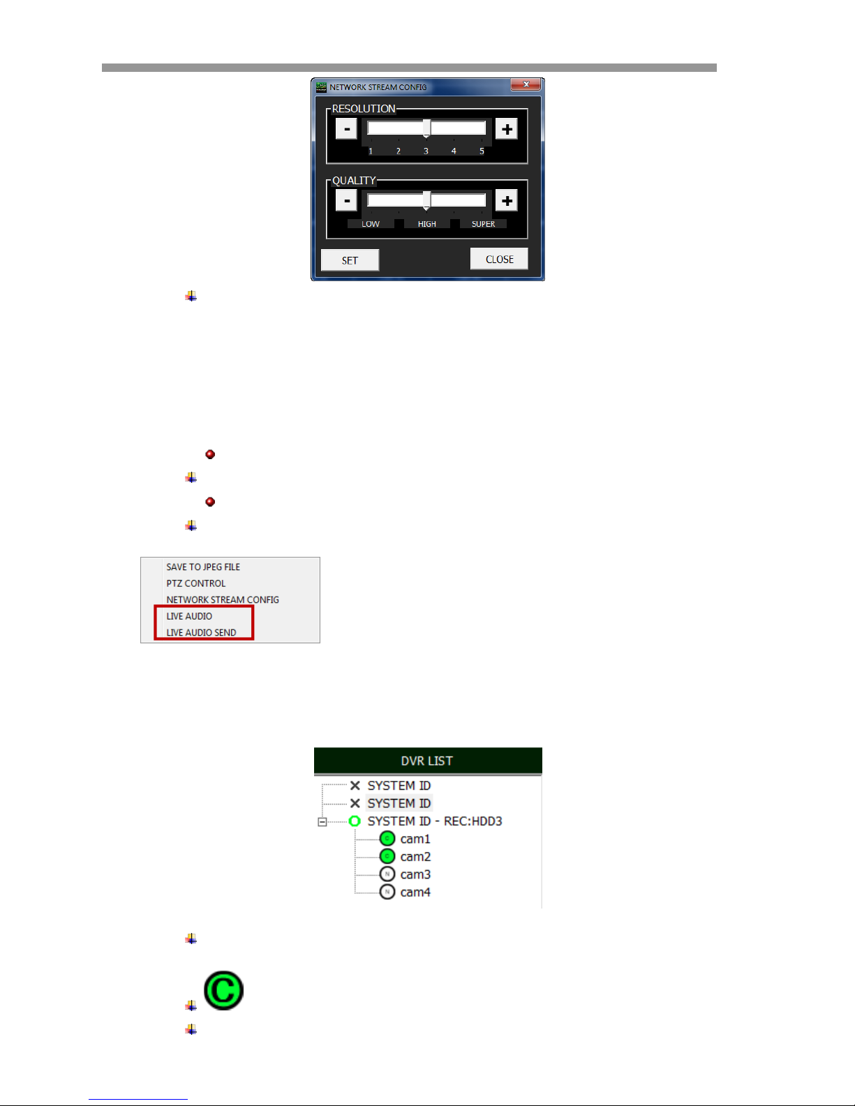
: Open the ‘Network Stream Config’ panel where you can choose the
resolution and the quality for the live video. The changes will affect all channels.
Page 83
VT-HDOC Series
82
1: Resolution selection (5 levels)
HD SDI DVR
Level 1: 720p : 320x180 / 1080p : 480x270
Level 2: 720p : 640x180 / 1080p : 960x270
Level 3: 720p : 640x360 / 1080p : 960x540
Level 4: 720p : 1280x360 / 1080p : 1920x540
Level 5: 720p : 1280x720 / 1080p : 1920x1080
Default Value: 640x360 for 720p, 960x540 for 1080p
2: Modify the quality of video (5 steps): LOW,NORAL,HIGH,BEST,SUPER
Default Quality: ‘HIGH’
3: Apply of modification (SET) and close the panel
: You can hear audio from the selected camera..
7.3.5.5 DVR List
The ‘DVR List’ shows the DVRs registered using the ‘CONNECTION MANAGER’. On the DVR List panel, you
can connect/disconnect the DVR, execute the Player for the remote searching and playback, and see the
status information of DVR.
SYSTEM ID – REC:HDD1 : [The name of DVR]:[HDD number], HDD number means the HDD index
currently be accessed for recording.
: Show the recording type or status..
Richt clicking the DVR name in the DVR list pops up the menu to connect/disconnect DVR or
Page 84
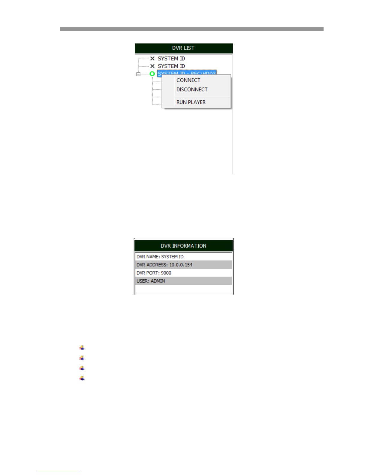
VT-HDOC Series
83
execute the Player for search & playback.
CONNECT: Connect to the selected DVR
DISCONNECT: Disconnect the selected DVR
RUN PLAYER : Execute the Player for the remote search & playback.
7.3.5.6 DVR Information
This panel shows information of the DVR which is currently highlighted in the DVR List.
7.3.6 PLAYER
The Player supports the following features:
Live video monitoring for the connected DVR
Remote search and playback
Download the recorded data from the DVR(remote copy)
Control a PAN/TILT camera movement
7.3.6.1 Initial Screen
Executing the ‘Player’ opens the application separate from the web browser and shows the login
window such as below picture.
Page 85
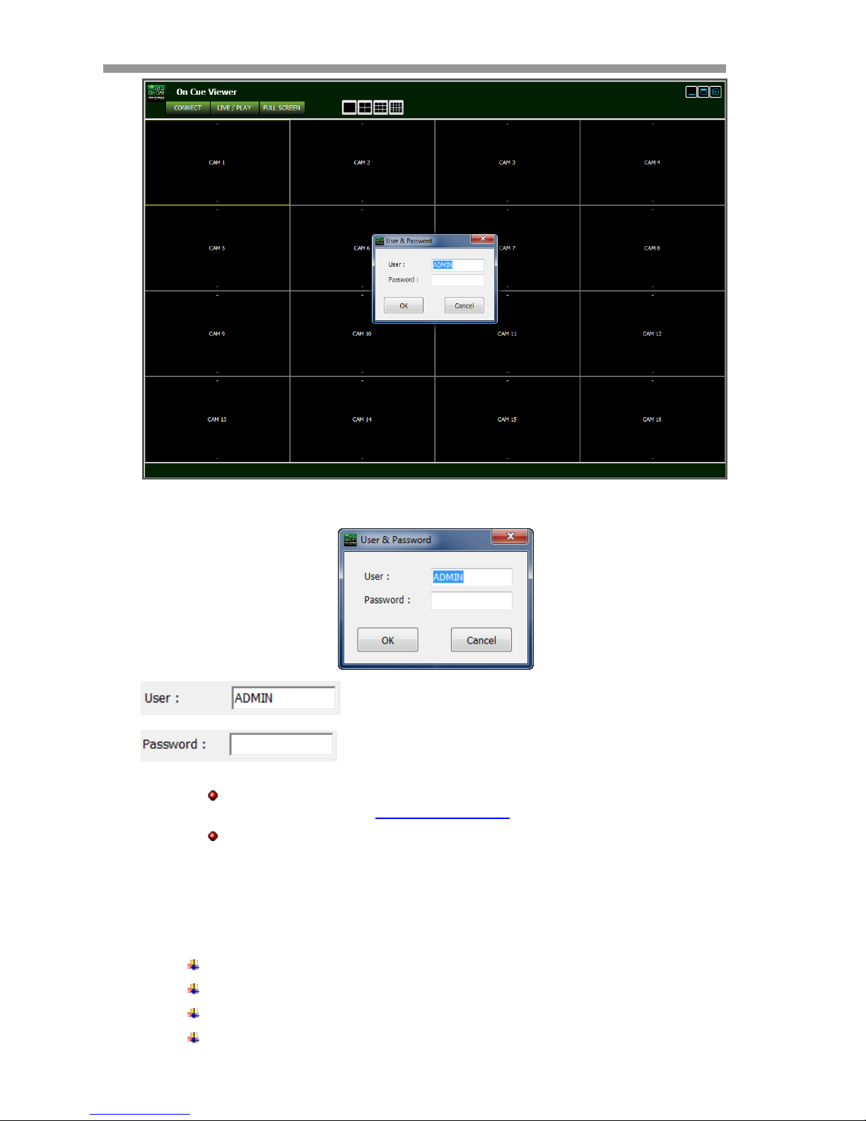
VT-HDOC Series
84
7.3.6.2 Log In
: Enter the USER name of DVR registered in the DVR
: Enter the password for the selected user.
The user authority and allowed functions, live preview, search & playback, PTZ control and
etc., are controlled by the USER AUTHORITY setting in the DVR setup
USER ID and password is case-sensitive.
7.3.6.3 Live Preview
After login, the live preview screen will be shown.
Features
User log-in/out feature (RECONNECT)
Monitoring the live prewview
Snapshot and save the preview video as JPEG
(Admin Only) Control the resolution and quality for transferred video stream directly
Page 86

VT-HDOC Series
85
The colored rectangle around video shows the currently selected camera
1: Application Title
2: Display split mode selection
: Single camera view
: Quad split view
3: WEB Viewer Minimize/Maximize/Close
: Minimize the window
: Maximize the window
: Exit the ‘Web Viewer’
4: Reconnect/Live&Search/Full Screen
: Log out and Reconnect
: Switching between the live preview and the search & playback
: Full screen video view. Press ‘ESC’ to return to the window
5: Date & Time of Camera transferred from the DVR
6 : Channel Title and the resolution of the transferred video
Resolution Steps for HD SDI DVR:
720p Camera: 1280x720 / 1280x360 / 640x360 / 640x180 / 320x180
1080p Camera : 1920x1080 / 1920x540 / 960x540 / 960x270 / 480x270
Default Resolution: 720p Camera: 640x360, 1080p Camera: 960x540
Page 87
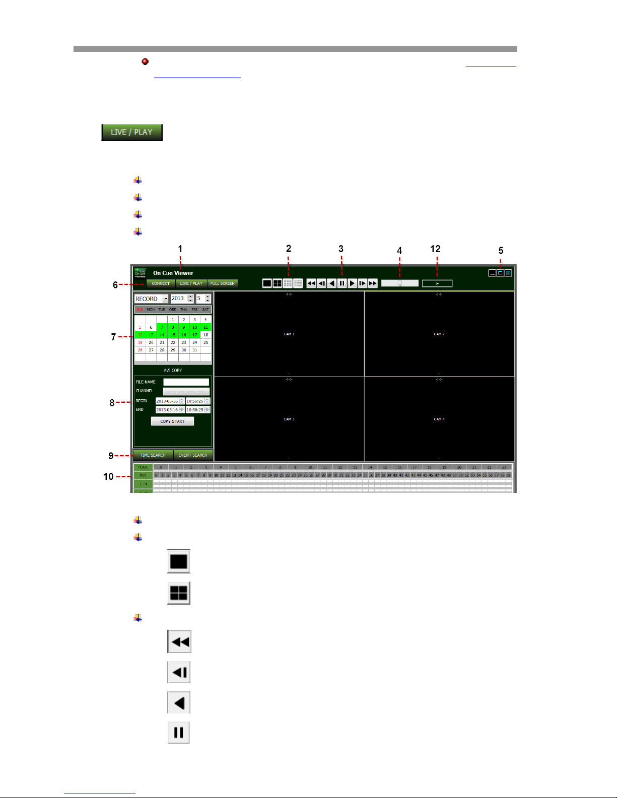
VT-HDOC Series
86
For details about the JPEG Snapshot/PTZ Control/Video Configuration, refer to the same
feature of Web Viewer.
7.3.6.4 Search & Playback
Toggles between the search & playback window
Features
User log-in/out feature (RECONNECT)
Swiching between the live preview and the search & playback
Search & Playback
Copy the recordings from the DVR to the PC remotely
1: Application title
2: Split mode selection.
: Single camera view
: Quad split view
3: Playback speed control
: Reverse Fast
: Reverse Slow
: Reverse Normal Speed
: Pause
Page 88
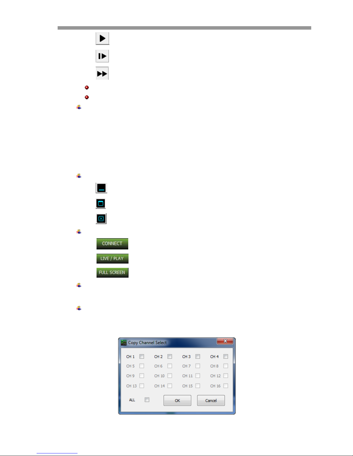
VT-HDOC Series
87
: Forward Normal Speed
: Forward Slow
: Forward Fast
Steps for fast playback : x2, x4, x8, x16,x30, x60, x120
Steps for slow playback : 1/2, 1/4, 1/8, 1/16, 1/30, 1/60, 1/120
4: Fast Playback Speed & Direction Control Bar
Mouse wheel up: fast forward
Mouse wheel down: fast reverse
Center click: normal speed playback
Click on the right half of bar : fast forward
Click on the left half of bar: fast reverse
7 level speed control for each direction
5: View window control
: Minimize the window
: Maximize the window
: Exit the ‘Web Viewer’
6: Reconnect/Live&Search/Full Screen
: Log out and Reconnect
: Switching between the live preview and the search & playback
: Full screen video view. Press ‘ESC’ to return to the window
7: Calender Panel: show the selected date for searching. The green color indicates that the
recording data exist. Click the date will tigger the searching for the selected day. The searching
result is displayed on the time selection table (10).
8 : Copy the recorded video in the DVR to the PC
TAG name: Folder name where the copied AVI file will be saved.
Channel: Choose the desired channel(s) to be copied
From: The start time of the recorded data to be copied
Page 89
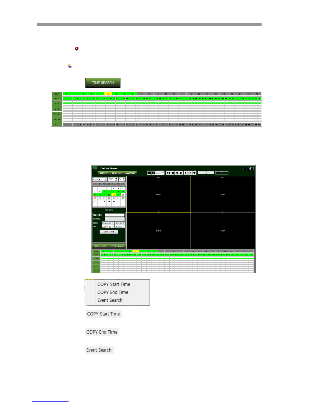
VT-HDOC Series
88
To: The end time of the recorded data to be copied
Copy Start: Begins the copy operation
TAG name and Channel have to be defined before user can copy.
9 : Choose search type: ‘EVENT’ or ‘TIME’. The time selection table tagged ‘10’ in the above
picutre is used for one of this two search type
: select the search mode to ‘Time Search’.
Yellow colored cell indicates the selected hour and minute.
Green colored cells mean there is continuous recorded data.
Red colored cells mean there is event recorded data.
Double-click on the cell in the minutes bar will start the playback from the selected time.
: Right-click the minute bar to show the pop-up menu
: Takes the ‘COPY START TIME’ from the selected time cell and puts it
into the ‘From’ of the COPY control panel.
: Takes the ‘COPY END TIME’ from the selected time cell and puts it
into the ‘To’ of the COPY control panel.
: Takes the time for ‘EVENT SEARCH start time’.
Clicking on the ‘seconds’ bar will move the second of playback video to the selected
second. This is only available while playback on-going.
Page 90
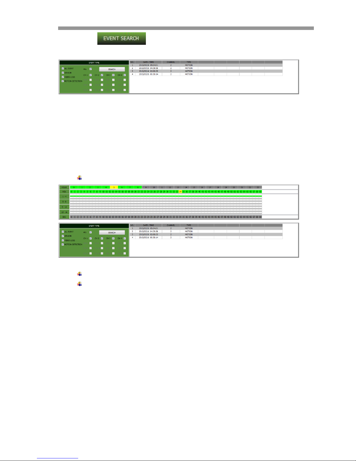
VT-HDOC Series
89
: Select the search mode to ‘EVENT Search’.
Event Type(Search Condition)
All: For all kinds of recording events
Sensor: sensor input event
Video Loss: lost video event
Motion Detection: all motion events
CH ALL: Searching for all channels
CH1/CH2/CH3/CH4: choosing the channel to be searched
Research: execute the event search again
10: Time selection & recording indication table / Event search result window
11: display the playback video as a result of searching.
12: show the current playback mode, speed and direction.
Page 91

Detailed Specifications VT-HDOC4 VT-HDOC8
Video Input / Resolution
Main Monitor Output
Sub Monitor Output
Spot Output
Audio In/Out
Alarm In/Out
Recording Compression
Recording Multi Operation
Recording / Playback (720p Source)
Recording / Playback (1080p Source)
Live Display Speed (Max)
Individual Network Streaming
Simultaneous Network Connections
Recording Mode
Motion Detection
Storage Interface
SATA HDD Inputs
eSATA
Max Supported HDD Size
Data Redundancy (Mirroring)
External Backup
System Control
Network
Ethernet Port
Hybrid Camera Operation
Remote Viewing Software
Network Streaming
Adjustable Access Levels Per User
Digital Zoom
Panorama Search
PTZ Tour Event Preset
Sensor Triggered PTZ activation
Motion Sensor Display
DDNS
Email Notification with Snapshot
Power
Operating Temperature
Dimensions (W x H x D)
Weight
1 HDMI
1 VGA (up to 1920x1080)
1 BNC
4 line in (RCA) / 1 line out (RCA) & HDMI Audio Output
H.264
Pentaplex (Live, Playback, Recording, Backup, Network)
20fps @ 1080p / 30fps @ 1920x540 / 60fps @ 960x540 / 60fps @ 960x270 / 120fps @ 480x270
Up to 8
Continuous, Event (Motion, Alarm, V-Loss), Schedule
16 x 12 Grid
SATA2 / SATA3 (Supports Advanced HDD Formatting)
2 SATA HDD Max. (2x Internal HDD OR 1x internal HDD & 1x External via eSATA)
OPTIONAL (uses 1 internal port)
Up to 4TB each using Advanced Format (Up to 8GB Internal Storage)
Dual Recording Mode (Individually Selectable per Camera)
AVI Format to USB Device (HDD, Thumb Drive, etc.) & Network
USB Keyboard, USB Mouse, Included IR Controller
LAN (TCP/IP Ethernet, RJ45), DHCP, Dynamic IP, DDNS, uPNP, HTTP, NTP
10M / 100M
YES with optional 4-channel breakout box (Model VT-QHD4)
CMS / Web Browser / Mobile (iOS/Android)
WQCIF / 2WCIF / WCIF / 2WCIF / WD1
Search & Play / Archiving / DVR Setup / PTZ Control / Power Off
Linear scale for Live & Playback
YES
YES
YES
YES
YES
YES
12VDC Adapter (3A)
41~104 °F (5~40 °C) / 20~80% RH
13.39” x 2.76” x 9.84” (340 x 70 x 250mm)
4.41 lbs. (2kg)
4 CH HD-SDI Inputs
4 In / 1 Out (Relay)
320x180 / 640x360 / 1280x720 @ 120fps
480x270 / 960x540 / 1920x1080 @ 60fps
120fps @ 720p / 120fps @ 1080p
8 CH HD-SDI Inputs
8 In / 1 Out (Relay)
320x180 / 640x360 / 1280x720 @ 240fps
480x270 / 960x540 / 1920x1080 @ 120fps
240fps @ 720p / 240fps @ 1080p
Page 92

VITEK LIMITED PRODUCT WARRANTY
VITEK products carry a three (3) year limited warranty. Digital recording and storage products
are also warranted for 3 years except for the hard drives which carry their own independent factory warranty from the hard drive manufacturer. VITEK warrants to the purchaser that products
manufactured by VITEK are free of any rightful claim of infringement or the like, and when used
in the manner intended, will be free of defects in materials and workmanship for a period of three
(3) years, or as otherwise stated above, from the date of purchase by the end user. This warranty
is non-transferable and extends only to the original buyer or end user customer of a Vitek Authorized Reseller.
This warranty shall not apply to repairs or replacements necessitated by any cause beyond
the control of VITEK, including but not limited to, acts of nature, improper installation, excess
moisture, misuse, lack of proper maintenance, accident, voltage fluctuations, or any unauthorized tampering, repairs or modifications. This warranty becomes VOID in the event of alteration,
defacement, or removal of serial numbers.
Within the first 6 months of purchase, VITEK will replace or credit any defective product at the
request of the customer (subject to availability) with a new product that equals or exceeds the
performance of the original product purchased.
Within the first 6 months of purchase, at its sole discretion, VITEK may issue an advance replacement for a defective product; however, all related costs including, but not limited to shipping and/
or delivery charges will be the responsibility of the customer. If upon return inspection a product
is determined to be in good working order or shows evidence of misuse, the customer will be responsible for full payment of the original product purchased as well as the replacement product.
Beyond the first 6 month period for the remainder of the warranty, VITEK’S responsibility shall be
limited to repairing the defective product, including all necessary parts and related labor costs.
At its sole discretion, VITEK may choose to either exchange a defective product or issue a merchandise credit towards future product purchases. Any replacement parts furnished in connection with this warranty shall be warranted for a period not to exceed the remaining balance of the
original equipment warranty.
A Return Authorization number or “RA” number must be obtained prior to the return of any item
for repair, replacement, or credit. VITEK requires that this “RA” number be clearly printed on the
outside of the shipping carton to avoid refusal of said shipment. The Return Authorization number
expires after 30 days. Products returned after the 30 day period will be subject to refusal. Shipping charges, if any, must be prepaid. A copy of the bill of sale (or invoice of purchase), together
with a complete written explanation of the problem must accompany all returns.
Vitek makes no warranty or guarantee whatsoever with respect to products sold or purchased
through unauthorized sales channels. Warranty support is available only if product is purchased
through a Vitek Authorized Reseller.
Page 93

28492 CONSTELLATION ROAD VALENCIA, CA 91355
WWW.VITEKCCTV.COM | 888-VITEK-70
 Loading...