

Page 1

VT
-
DVR04
4 CHANNEL DIGITAL
VIDEO RECORDER
User’s Manual
Version 2.1
Page 2

TABLE OF CONTENTS
Forward
Safety and Precautions
2
Getting Started
3
Front Panel
4
Power
4
Audio Selector
4
Video Selector
4
Playing Back Recorded Images
5
System Status LED
5
System Status LED
5
Remote Control Sensor
5
USB Port
5
Rear Panel
6
AC Power Socket (100V-260V)
6
Video Output Terminal (BNC Connector)
6
Audio In Terminal
7
Video Export (RCA Connector)
7
Video Export (RCA Connector)
7
Network Terminal (RJ 45)
7
External Remote Control Sensor Terminal
7
External Alarm Out
7
External Sensor In
7
RS 485 Terminal (P/T/Z/F)
7
Remote Control
8
Using the Remote Control
9
Remote Control Functions
10
Power On/Off
10
Event Log Display
10
OSD (On Screen Display) On/Off
10
M/D (motion detection) Area Display On/Off
10
Network Status
10
Sensor Off
10
Alarm On /Off
10
Video Screen Selector
10
Audio Selector
11
Playback Controls
11
Directional and Enter Keys
11
Menu
11
Exit/Live
11
P/T and Z/F
11
VISS Find/Set
11
R/C (remote control) SET
11
Help
11
Menu – System Configuration
12
Recording Schedule
12
Compress Ratio
12
Alarm Link
12
Password Change
12
Disk Info
12
Recording Speed
12
Spot Monitor
12
Motion Detection
12
P/T/Z/F Setup
12
Misc. Menu
12-13
Trouble Shooting
2
14
Page 3

FORWARD
Thank you for purchasing your VT-DVR04, a state of the art Digital Video Recorder
(DVR) utilizing the latest available video processing technology.
This version of the User’s Manual was written in March 2003. The contents of this
manual, the DVR’s capability, and other information may be changed or revised
without prior notice.
Please read the User’s Manual in its entirety before installing and operating the DVR.
Please keep this guide in a safe place for future reference.
We, at Vitek, have developed a Digital Surveillance System Chip, a central processing
unit, that achieves real-time outputs to each of 4-channels of video. We have increased
the compression rate by employing MPEG-2 technology that enhances the core function
of image preservation--the essence of a security system. For your convenience, we have
included a patented front panel and a remote control with the system. This unique
feature allows the user to use this technologically complex system without prior
knowledge of operating a computer system. VT-DVR04 is a state of the art DVR security
system that can be monitored from anywhere in the world through a Network Interface
Card (NIC) and a DSL or secured line.
Safety and Precautions
1. Only use the power source provided with the product.
2. Do not block the vent as the system may over heat, malfunction, or catch fire.
3. Keep away from direct sunlight and place the product where there is adequate
ventilation.
4. Keep this product away from moisture and do not touch the product with wet
hands.
5. Do not place any items on top of the VT-DVR04.
6. Do not drop or mishandle during transport.
7. Only use accessories that have been approved by Vitek. Keep the product level
during operation.
8. All hard disks and backup disks used with the system must be provided by Vitek.
9. In the case of a malfunction, please contact your local dealer or an authorized
service person. Warranty will be null and void if the product is disassembled or
manipulated by the user.
2
Page 4

The following items are included with the VT-DVR04. Please be certain that all
o
Getting Started
NOTE
items are included upon opening the carton:
1. Components
o VT-DVR04 (main component)
o Remote Control (batteries included)
o Power Cable
o User’s Manual
o Warranty Card
o Software Diskettes (Set of 2)
Rack Mount Bracket
1. Remote control uses two AAA batteries.
2. Battery life depends on usage.
3. Please keep extra batteries handy for future use.
3
Page 5
Product Information
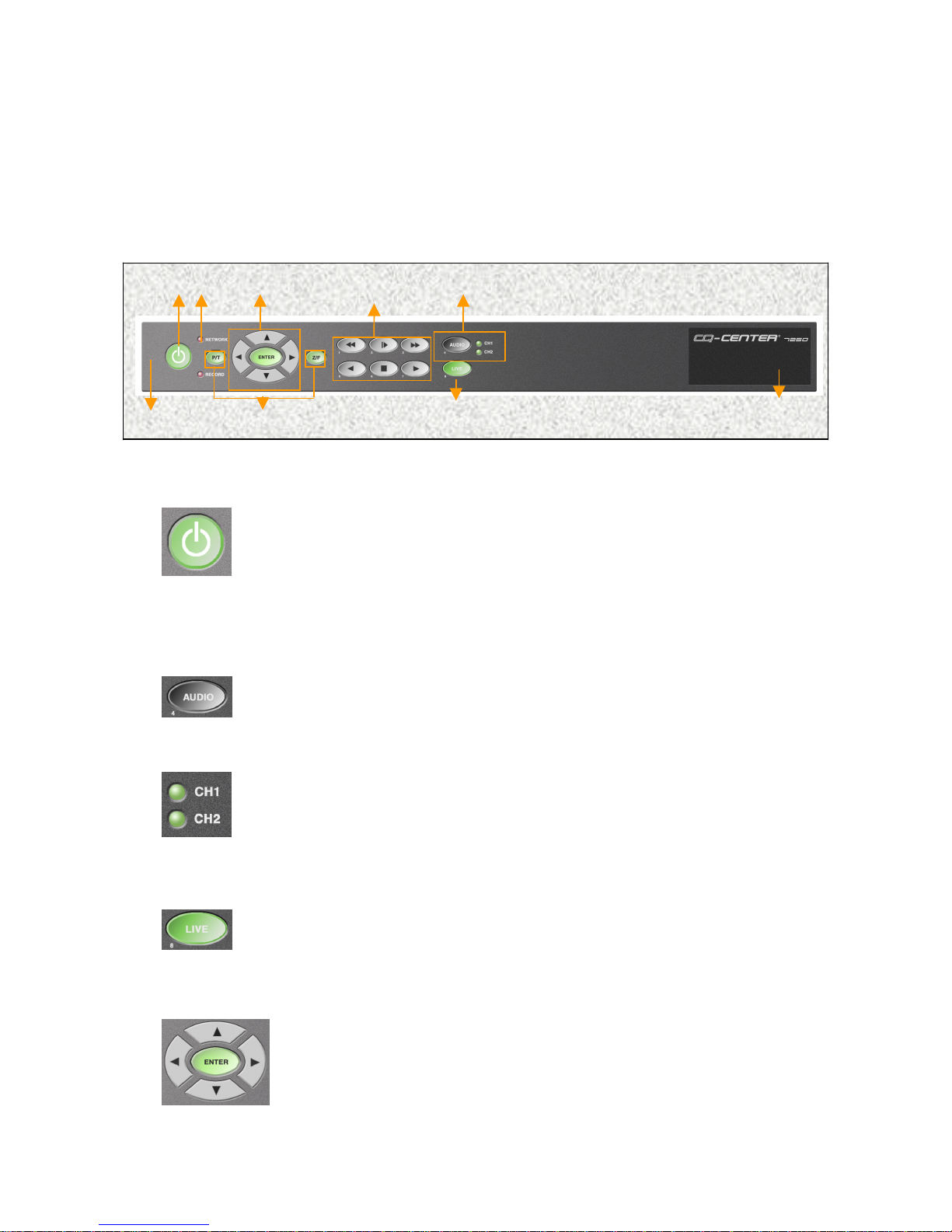
1. Front Panel
8 2 3 5 6 1 7
The Audio button is used to select the desired audio channel. By
1. Power
2. Audio Selector
Power On/Off Button. Power Off is indicated by RED and Power On
status is indicated by GREEN. To turn the system on, press the Power
3. Video Selector
4 9
key. The key should turn amber. Enter the password (default is 1111)
using the remote control and press the power key again. The key should
The key should turn green and the system should become active. To turn
the system off, repeat the above step.
pressing this button, the user will scroll through CH1, CH2, and MUTE.
Select the desired audio channel for playing back recorded audio.
The Green light Indicates the selected audio channel. When both
indicators are not illuminated, this signifies MUTE status.
The Green LIVE button indicates that the system is in the live viewing
mode. This button is also used to return the system to live viewing
mode from the playback mode.
When in live mode, the user can select a screen to be viewed as a
single, full screen. A channel can be selected by using the directional
key *(the channel number will be illuminated in yellow). Once selected,
the user can view the channel full screen by pressing the ENTER key.
To return to the quad m ode, press the ENTER key again.
4
Page 6
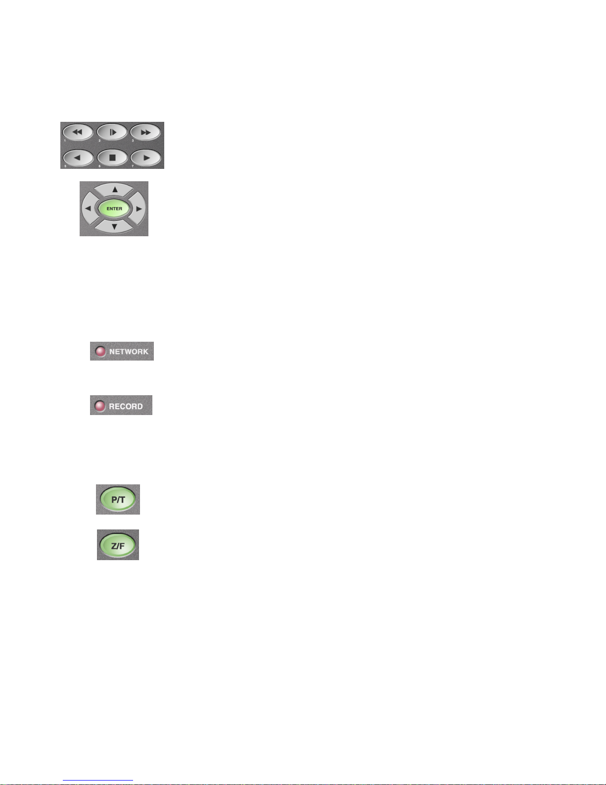
4 & 5. Playing Back Recorded Images
6. System Status LED
When lit, the light indicates that there is a remote user connected to the
8. Remote Control Sensor
The Playback buttons consist of Frame Advance, Fast Forward, Forward
7. P/T/Z
/F Control
9. USB Port
Play, Stop, Reverse Play, and Fast Reverse.
To get to the playback mode, simply press any one of the playback
buttons. Then press the STOP button. This will take the user to the time
selector mode. Note: The first digit in the time will begin to blink. Select
the desired time by pressing the up or down cursor. Press the right
or left cursor to skip to the next digit, then press the PLAY button.
system.
When lit, the light indicates that system is currently recording.
If the system is connected to a P/T/Z camera, the camera can be controlled
from the system. From the live, single screen mode, press the P/T or the
Z/F button. Camera can be controlled with the cursor keys.
To capture a footage (approximately 2.5 seconds), insert a USB Memory Stick and
press enter. Video may also be recorded to an external VCR by use of the video
export connector located at the rear of the unit.
5
Page 7
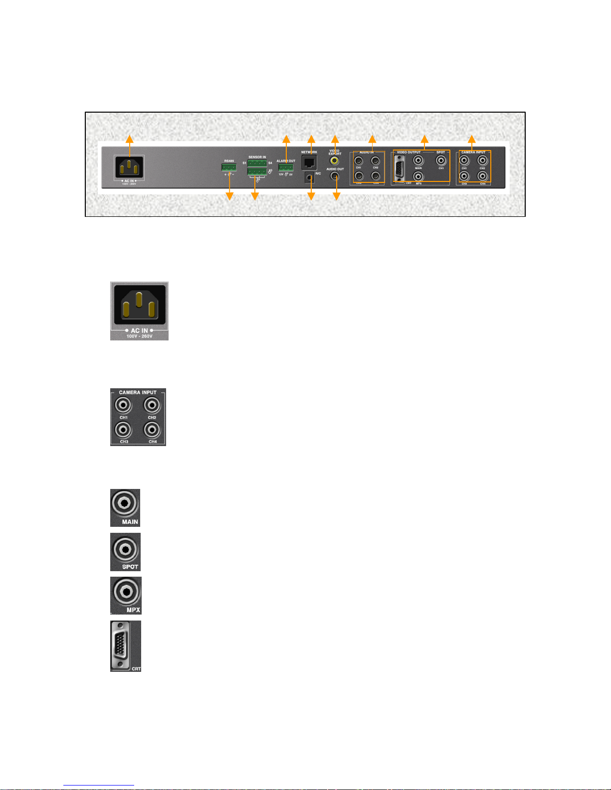
2. Rear Panel
1. AC Power Socket (100V
-
260V)
Insert the provided accessory power cord here.
4 3 2 1 11 8 6 10 5 9 7 2. Video Input Terminal (BNC Connector)
3. Video Output Terminal
(BNC Connector)
Secondary Option. User can view the Live and Playback
screens through a computer monitor. CANNOT BE USED
There are total of four camera inputs.
Main Monitor. Live and Playback is shown with the On Screen Display
(OSD). CANNOT BE USED SIMULTANEOUSLY WITH OPTIONAL
COMPUTER MONITOR CRT OUTPUT.
Switch Monitor. Up to Four cameras can be programmed to
switch sequentially.
Multiplex Output. Four screens are shown without
OSD.
Main MonitorSIMULTANEOUSLY WITH THE MAIN MONITOR.
6
Page 8
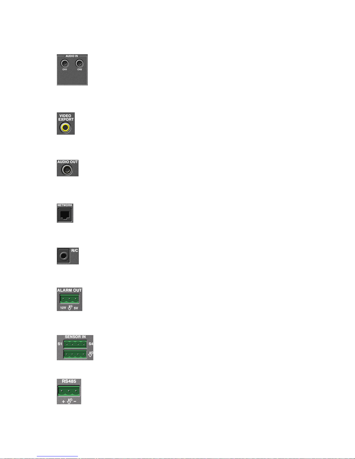
4. Audio In Termin
al
System can record up to two audio inputs.
5. Video Export (RCA Connector)
6. Audio Output
7. Network Terminal (RJ 45)
8. External Remote Control Sensor Terminal
9. External Alarm Out
12V and 5V output can be selected and can be connected to an external
10. External Se
nsor In
11. RS 485 Terminal (P/T/Z/F)
System will export recorded images to a VCR or to TV. This
allows The user to record desired footage in VTR analog format.
Will playback a single, selected audio channel.
Network port for remote access.
For use with IR repeater if unit is located in a remote area (equipment
closet, ETC.).
alarm system. (Normal : Low)
Up to four Open/Close Relay type Sensors can be connected to the system.
Direct connection to supported PTZ with RS485 operation. Converter will
be necessary for other data formats (i.e. RS422, ETC.).
7
Page 9
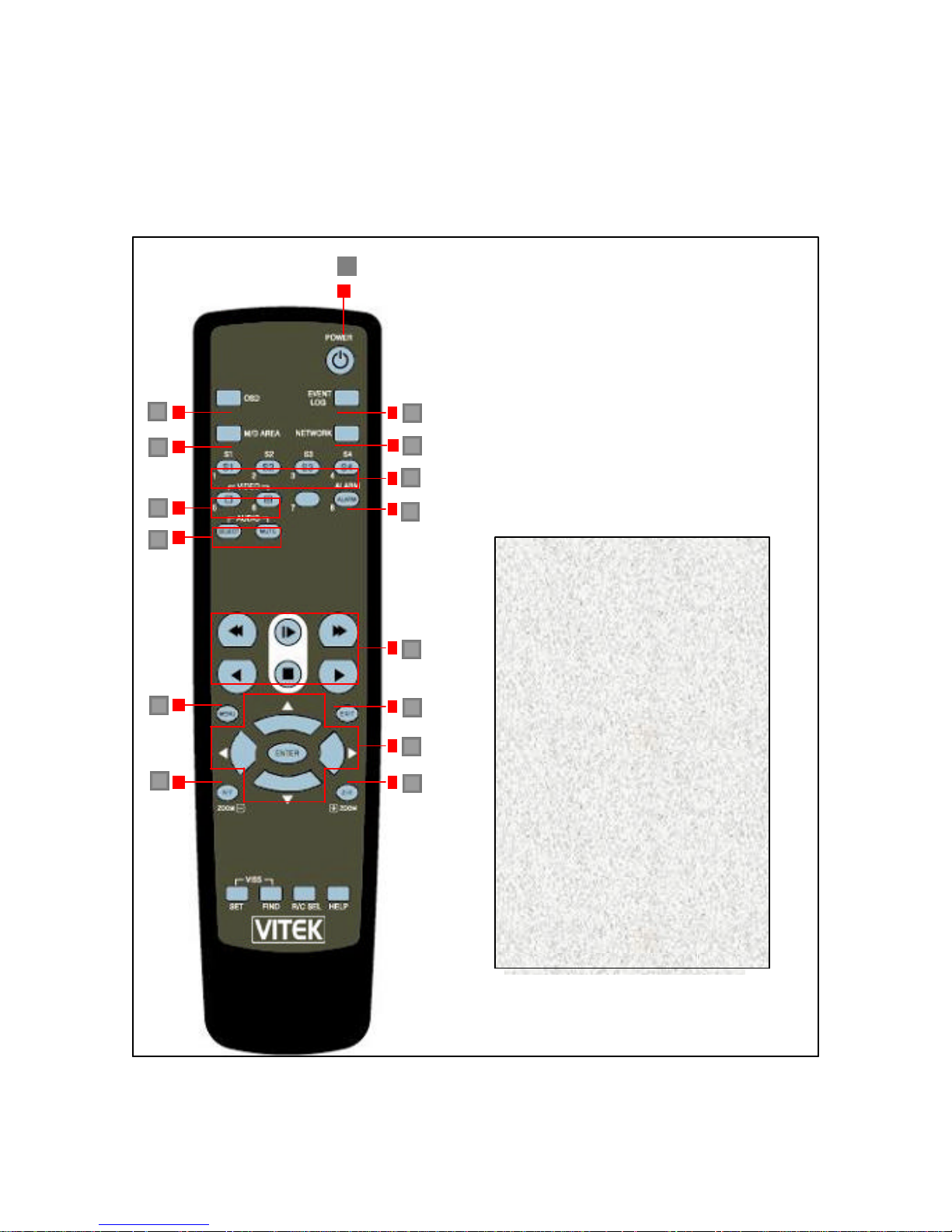
1. Power On/Off
Remote Control ID Selector
software / firmware
3. Remote Control
1
2 3 6 7 4 5 9 12 14 16 17 10 8 11 13 15 14
2. Event Log
3. OSD On/Off
4. M/D (motion detection)
Area indicator On/Off
5. Network Status Indicator
6. Sensor Off (S1-S2)
7. Alarm On/Off
8. Video Selector
9. Audio Selector
10. Playback Controls
11. Directional keys and Enter
12. Menu
13. Exit
14. P/T/Z/F
15. VISS Set/Find
16.
17. HELP –
version
8
Page 10

There are two methods of configuring the VT-DVR04: from the site where VT-DVR04 Is
Access Configuration, please refer to the
to 16 feet away (at angles not
Another
without using
Using the R
emote Control
installed and through the Network Connection.
Following are the description for configuring the VT-DVR04 at the site. For Remote
REMOTE software User’s Guide.
1. Remote Control
The remote control uses infrared (IR) and can be used up
exceeding 60 degrees) from the VT-DVR04. IR transmitter is located at the center of
the remote control and should face the VT-DVR04.
2. VISS SET-FIND
The VISS SET-FIND Button on the remote control allows the user to bookmark a given
incident during playback and automatically return to that incident
3. Keypad
prominent feature of the VT-DVR04 is the keypad located on the front panel.
Unlike it’s PC based competitors, this allows for complete operation of the VT-DVR04
a computer keyboard.
9
Page 11

REMOTE CONTROL FUNCTIONS
2. Event Log Display
3. OSD (On Screen Display) On/Off
4. M/D (motion detection) Area Display
On/Off
5. Network Status
Indicates the network status of the system. If there is an unwanted network intrusion,
6. Sensor Off
7. Alarm On /Off
8. Video Screen Selector
•
1. Power On/Off
Power On/Off Button. Power Off is indicated by RED and On status is indicated by
GREEN. To turn the system on, press the Power key. The key should turn amber.
Enter the password (default is 1111) and press the power key again. The key should
turn green and the system should become active. To turn the system off, repeat the
above step.
User can select the Event Log to be displayed or not. When the log is displayed,
user can select an event with the directional keys and when the ENTER button is
pressed, the system will playback that selected event. NOTE: Event log is only
possible when The system is set to “Event Recording.”
user can manually disconnect the network
User can turn off the four Sensors connected to the system.
User can activate or deactivate the alarm connected to the system.
button: Single Screen Mode.
• button: Multi Screen Mode
10
Page 12

9. Audio Selector
Select button: Can select between CH1 and CH2. During Live View mode, audio
10. Playback Controls
The Playback buttons consist of Frame Advance, Fast Forward, Forward Play, Stop,
11.
Directional and Enter Keys
12. Menu
13. Exit/Live
Used to go back to the previous screen when in the “Menu” mode.
14. P/T and Z/F
15. VISS Find/Set
16. R/C (remote control) SET
ple units in a close proximity, each remote control can
17. Help
For system configuration. See Menu-System Configuration on next page.
monitoring is possible. During Playback mode, user can listen to the recorded
audio.
Mute button: Mutes the audio function.
Reverse Play, and Fast Reverse.
Used to go back to Live View mode from the Playback mode.
This is the system ’s video bookmark. Up to five marks can be set for quick review. By
Pressing the VISS set, the user can mark the beginning of a desired footage. By
pressing find, the user can view the marked footage.
In cases where there are multi
be programmed to operate with each specific unit.
Displays system information.
11
Page 13

Menu – System Configuration
In Live viewing mode, press the menu button on the remote control. Enter the password (factory
default is 2222). A graphic illustration of setup options will be displayed.
1) Recording Schedule – Using the left/right cursor and the enter button to select time
periods for event or continuous recording. Press exit once to return to the setup menu.
2) Compress Ratio – This is the overall image quality. The factory default is “GOOD” (or
medium) image quality. Use the left/right cursor to scroll between BASIC, NORMAL,
GOOD, HIGH and SUPER quality modes. The average usage per second will also be
displayed.
3) Alarm Link – Enables alarm output to be triggered upon camera motion (event) and/or
sensor input.
4) Password Change – Use to change password to the Menu – System Configuration
screen.
5) Disk Info – Displays total hard drive available and earliest as well as most recently
recorded images.
6) Recording Speed – This is a global setting for all 4 cameras. Recording speed cannot
be set individually for each camera. Use the up/down cursor to select 30fps, 15, 10, 5, 2,
1 etc. Hourly usage will also be displayed.
7) Spot Monitor – Use to set dwell time for sequencing cameras. Dwell time may be set
individually from 1 to 9 seconds between cameras. The Spot Monitor output is located in
the rear of the unit.
8) Motion Detection – Use to set sensitivity and area of detection for each individual
camera. There are 3 sensitivity levels. Minimum – Use primarily for outdoor cameras to
avoid false events. Default is the center setting (use for most applications). Max – use for
confined areas with little activity. Enable is used to define the area of detection. Use the
down cursor to select “Enable”. Press “Enter” once to select camera to define and again
to display the area definition grid. The grid represents the selected camera area located
in a given quadrant. Press the enter button to deactivate any of the 48 cells shown. Use
the up/down and left /right cursors to navigate to other cells. Repeat this process to set
up activity area on all cameras.
9) P/T/Z/F Setup – Press “Enter” to select camera input with Pan/Tilt function. Use up/down
cursor to choose P/T data protocol being used. Repeat process for up to 4 P/T/Z units.
10) Misc. Menu -
Software Upgrade – Insert upload into USB port located on the front left side of the
unit and press enter.
I.P. Address Set – Enter I.P. Address, Net Mask and Gateway as issued by provider
in order to enable remote communication.
System Refresh – Enter time to shut down and reboot the unit in order to de-fragment
the operating system.
12
Page 14

T/D Change – Enter the correct Time/Date and Format to be displayed on the OSD.
The system can display Month/Day/Year or Day/Month/Year.
Remote Control – Enter remote control ID when using more than 1 unit in the same
proximity.
Color Tune – Each camera can be adjusted individually for brightness, contrast,
saturation and hue.
Camera Name – Change the On Screen Display (OSD) camera title. Press “enter” to
select camera. Move box to desired characters and press enter. Use the < to erase
characters.
Main Monitor – Use to select main monitor output as computer (CRT) or composite
(TV). After selecting, you must reboot the system for it to recognize the output.
13
Page 15

1. Power switch does not function.
o Connect the AC power cord securely.
2. The Clock is showing incorrect time.
3. Local Sensor Name Remains Highlighted on the Main Screen.
4. The screen is not clear.
please refer to the Setting Video Color section of the Configuration
5
. The remote control does not work.
o
TROUBLE SHOOTING
o Make sure that POWER key is RED (illuminated).
o If the POWER key is RED, input the Password using the [A1]-[D4] buttons
and press the POWER key again.
o If the problem persists, please contact the professional installer or the
security manager.
o Refer to the Menu-System Configuration section of the User’s Guide and enter
the correct time.
o If the problem persists this indicates that the mercury battery is low.
To replace the battery, contact the professional installer or the security manager.
o If the problem still persists after replacing the mercury battery, please contact
After Service Center located in the back of the User’s Guide.
o When an “event” occurs, the Local Senor remains highlighted until
inactivated by the user. The user must select the highlighted
Sensor and inactivate it.
o The displayed images and the images that were compressed and restored
are programmed to be of the same quality. If you are not satisfied with the
display,
chapter of the User’s Guide and manipulate the display.
o If you still feel that there is a significant difference, please recalibrate the
camera’s picture quality or replace the camera.
o The remote keyboard is battery operated. If the keyboard does not operate
properly, please replace the batteries.
o Please be certain that IR transmitter of the keyboard and IR receiver of the
DVR are in alignment.
The remote keyboard must be within 15 feet from the DVR.
o Please re-examine the camera’s operation using Recording section of the
User’s Guide as a reference.
o Restoration of images is only possible when images are recorded. Hence,
restoration will not occur if there are no images recorded.
o If recording is programmed as “On Event Recording,” there will be no
recording if there were no “events.”
14
Page 16

9970 GLENOAKS BLVD. UNIT B SUN VALLEY, CA 91352
PHONE: 888-VITEK-70 818-771-0300 FAX: 818-771-0400
WWW.VITEKCCTV.COM
 Loading...