

Vitek VTD-VPH Series Product Manual
VITEK
VTD-VPH
Vandal Resistant Color
Dome Camera Series
Product Manual
The VTD-VPH Vandal Resistant Dome Camera is a
smaller, more attractive camera ideal for use in
commercial or residential applications. It measures only 5”
in diameter and comes with a 24 Volt AC power input for
easy integration with standard cameras and power
systems. Versatile mounting and lens options allow you to
achieve perfect video images in virtually any environment.
All VTD-VPH domes feature Sony Super-HAD and/or
Ex-View Technology with Hi-Resolution of 480 Television
Lines.
2
CONTENTS OF PACKAGE
• One Fully Assembled VTD-VPH Series Dome Camera
• One Additional Knock-Out Plug
• One Tamper-Proof Wrench
• One Rubber Sealer Mat
• One Instruction/Installation Manual
• Assorted Additional screws for Convenience
Your VTD-VPH Dome Camera is designed to be flush or ceiling mounted on a wall or ceiling and
comes complete with a surface mount rear casing including conduit knockouts. Its patented 3-axis
gimbal allows for perfect viewing angles on any vertical or horizontal surface. An optional goose
neck wall mount (VT-VPHWM) is available if desired. The VTD-VPH Dome Camera is weather
sealed for indoor or outdoor locations.
The VTD-VPH Dome Camera should be powered by 24 Volts AC. Polarity is not important but you
should make sure that the power supply you are using is CSA Certified Class 2 Power Supply
delivering a minimum of 2.5 Watts.
For optimum video signal, use 95% copper shielded coax cable. Twisted pair or CAT-5E cable may
also be used with optional VT-TR1M Passive Video Transceivers. Maximum cable distance for 95%
copper braid coax is approximately. 800’; For Cat-5E or twisted pair, 2000’ using VT-TR1M
transceivers.
INSTALLATION OVERVIEW
WIRING CONNECTIONS
3
FLUSH MOUNT INSTALLATION
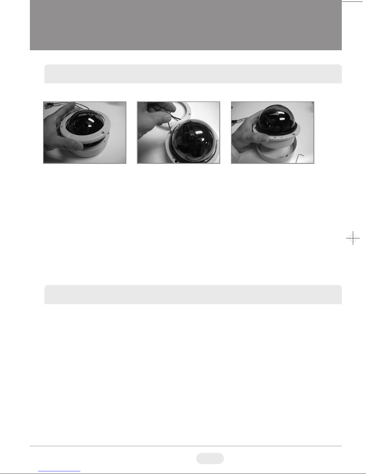
Begin by removing the three tamper proof screws in the outer bezel with the special wrench
included and removing it. Continue by removing the tamper proof screws on the inner casing (you
may want to remove and set aside the polycarbonate bubble to avoid scratching it).
Remove the inner casing from the outer surface mount casing and set the outer casing aside. You
may want to keep the surface mount box in case you decide to re-mount it at a later time.
Cut a hole in the ceiling or wall the exact size of the inner back box and set the camera into the
hole securing it with anchors. When installing in a drop ceiling always attach a guy wire to a beam
above the camera to hold the weight and secure the camera for safety reasons.
Begin by removing the three tamper proof screws in the outer bezel with the special wrench
included and removing it. Continue by removing the tamper proof screws on the inner casing (you
may want to remove and set aside the polycarbonate bubble to avoid scratching it).
Remove the inner casing from the outer surface mount casing (back box) and temporarily set the
inner casing/camera to the side.
Secure the outer back box directly to a wall or ceiling using wood screws or anchors. If installing
outside, remember to glue the rubber matting to the wall and then attach the back box. Conduit
may be attached to the rear or the side of the back box depending on the installation.
Re-secure the inner casing with the camera to the back box but remember to attach the wiring
before doing so. You may also want to find a desirable angle of view and adjust the iris and focus
before making the final wiring connections.
Remove Inner Screws Detach CasingRemove Top Bezel
SURFACE MOUNT INSTALLATION
 Loading...