

Page 1
VTD-TNMD4RFS
Transcendent Series 4
Megapixel H.265 IP Dome
Camera with IR LED Illumination
QUICK START GUIDE
VITEK
VITEK
FEATURES
1/3” 4.0 Megapixel Progressive Scan CMOS image sensor
• Up to 30fps live view @ 4 MegaPixel (2592x1520)
• 2.8mm or 3.6mm Fixed Iris Lens Options
• 10 Infrared LED’s with 65’ IR Range
• 120dB Super Wide Dynamic Range (WDR)
• True Mechanical Day/Night function by ICR
• XD-DNR (2D-DNR & 3D-DNR) Noise Reduction
• Fully Programmable Intelligent Analytics including Object Removal/
Museum Search, Line Crossing, and Area Intrusion Detection
• H.265/H.264/MJPEG Triple Streaming
• Secondary Video Output (CVBS)
• Remote Viewing via CMS, Internet Explorer, and iOS & Android
Apps
• ONVIF Compliant
• IP66 Weather Resistance & IK10 Impact Rating
• 12VDC & PoE (Power over Ethernet) Operation
PLEASE NOTE:
Complete User Guide, Software, Tools, and Updates are
available online. Scan the QR Code or visit:
http://www.vitekcctv.com/Downloads
Page 2
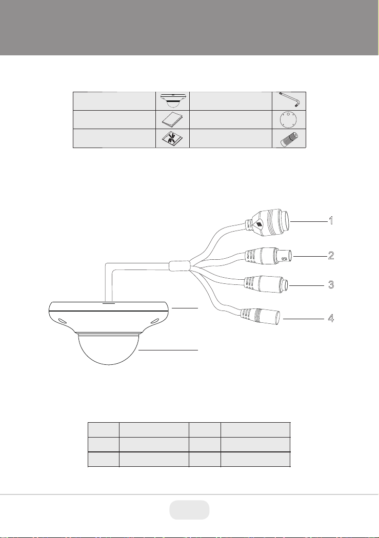
Components and Accessories
Camera
Quick Guide
Screws
Overview
Hex Wrench
Drill Template
Waterproof Cap
1
2
3
5
4
6
1
2
3
RJ-45 Ethernet
CVBS Output
Audio Input
Power Input
4
Mounting Base
5
6
Capsule
2 3
Page 3
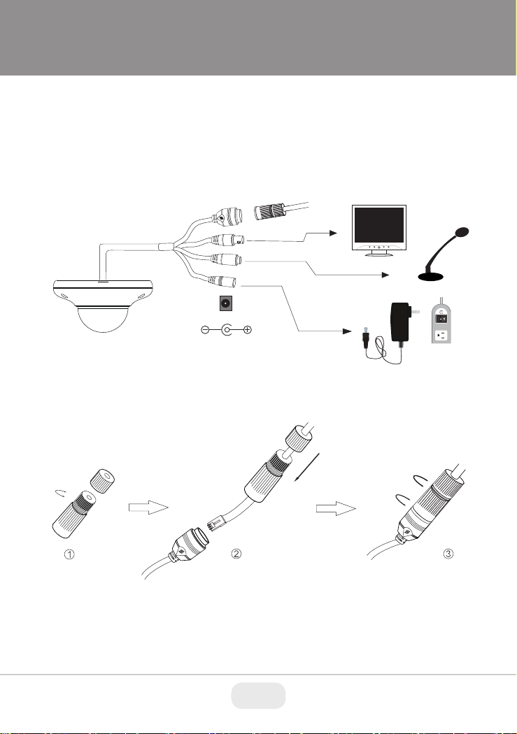
Network Cable & Power Connections
First connect the Waterproof Cap to an Ethernet patch cable, then
connect the cameras ethernet adaptor. If not powering the camera with
PoE, also connect the power Cable to an approved 12VDC Power
Supply.
Network Cable
12VDC
Optional 12VDC
Power Connection.
Not needed with PoE
Weather Resistant Network Coupler
1. Loosen the nut from the Weather Resistant Network Coupler,
2. Run ethernet cable through coupler, then attach a RJ-45 connector.
3. Tighten the nut and coupler for a weather resistant seal.
3
Page 4
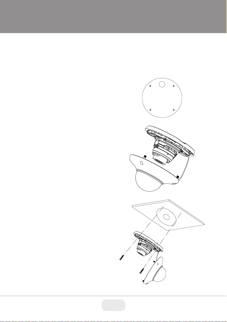
Installation
Before beginning installation, make sure that the wall or ceiling is
strong enough to withstand 3 times the weight of the camera. The
mounting steps are as follows:
1. Attach the drill template to
the place where you want to
install the camera, then drill
the screw holes and 1 cable
hole according to the drill
template.
2. Loosen the screws to open
the lower dome and then
loosen the lock screw to
remove the mounting base.
3. Route the cables and
connect the power & video
cables, use the rubber plug
to fill the gap of the mounting
base. then secure the
mounting base to the ceiling
or wall with screws.
4 5
Page 5

Installation
4. Before adjusting the three-axis camera mount, preview the
camera on a monitor, then adjust as necessary achieve the
optimum viewing angle.
Pan: 0°~360°
Rotation: 0°~350°
5. Install the dome bubble on the camera with the included screws,
then carefully remove the protective film to complete the installation.
Tilt: 0°~70°
5
Page 6

LAN Configuration
The camera can be accessed on the local network either using the
IP-Tool or directly in a web browser.
Accessing the Camera Using the IP-Tool
1. Make sure the camera and PC are connected to the LAN.
2. Locate the IP-Tool installer on the included Product Documentation
CD, then install on the PC. Open the installed application.
3. Modify the IP address. The default IP address is 192.168.226.201.
Click the information of the camera listed in the above table to show
the network information on the right side. Modify the IP address and
gateway of the camera and make sure its network address is in the
same local network segment as the computer’s. Please modify the
IP address of your device according to the practical situation.
For example, the IP address of your computer
is 192.168.13.4. So the IP address of the
camera shall be changed to 192.168.13.X.
After modification, please input the password
of the administrator and click “Modify” button
to modify the setting.
** Default admin password: “123456".
6 7
Page 7

4. Double-click the IP address and then the system will pop up the web
browser to connect IP-CAM . IE browser will download the Active X
control automatically. After downloading, a login window will pop up
as shown below:
Input the user name and password to log in.
Default user name: admin / Default password: 123456.
Directly Access Through a Web Browser
The default network settings are as shown below:
IP address: 192.168.226.201 HTTP: 80
Subnet Mask: 255.255.255.0 Data Port: 9008
Gateway: 192.168.226.1
You may use the above default settings when you log in the camera for
the first time.
1. Manually set the IP address of the PC and the network segment
should be as the same as the default settings of IP-CAM. Open the
network and share center. Click “Local Area Connection” to pop up
the following window.
Select “Properties” and then select Internet protocol according to the
actual situation (for example: IPV4). Next, click “Properties” button to
set the network of the PC.
7
Page 8

2. Open the IE Browser and input the default address of IP-CAM and
confirm. The IE browser will download Active X control automatically.
3. After downloading Active X control, the login dialog box will pop up.
4. Input the default username and password and then enter to view.
Rubber Plug
WAN Configuration
Access the camera by the router or virtual server for example.
1. Make sure the camera is connected to the LAN; Then log into the
camera via LAN and go to System Congfig→Network Config→Port
menu to set up the port number.
2. Enter System Config→Network Config→IP Address menu to modify
the IP address.
3. Go to the router’s management interface through IE browser to
forward the IP address and port of IP-CAM in the “Virtual Server”.
4. Open the web browser and input its WAN IP and HTTP port to
access the IP-CAM.
8 9
Page 9

NOTES:
9
Page 10

CONSIDER THESE OTHER GREAT
TRANSCENDENT PRODUCTS!
VT-TNR Series
Transcendent Series 4, 8, 32, and 64 Channel 5 MegaPixel H.265 Real
Time Network Video Recorders with 4K HDMI Output
FEATURES
• 4, 8, 32, and 64 Channel Stand-alone Real-time IP Network Video Recorders
• Full 5 Megapixel Real-time recording & playback
• 4K HDMI & VGA Video Outputs
• H.265 / H.264 Video Compression
• Plug and Play & Auto configuration for many leading ONVIF compliant IP Camera
models
• Internal PoE Switch (VT-TNR414P, VT-TNR818P, and VT-TNR3216P)
• 1 Gigabit LAN
• Pentaplex: Live Display / Record / Playback / Backup / Remote Access
• Supports SATA2/SATA3 HDD
• Applications for iOS® & Android®
• Remote Viewing over the Internet via Web Browser or LAN
• Mac OS® Client & CMS Central Management Software Included
• Supports both Dynamic and Static IP Addresses
• Web-based remote configuration
• Control locally via Front Panel Controls, USB Mouse, or with the Included IR Remote
control
Local Management, Viewing
Interface & Remote Viewing
with Web Browsers
Remote Viewing Using Mac
OSX
10 11
Apps Available for iPhone,
iPad, & Android Devices
Page 11

OPTIONAL ACCESSORIES FOR
TRANSCENDENT IP CAMERAS
VT-TJB01
Junction Box for
Cable Management
for use with all
Transcendent Bullet
and Turret Style
Cameras
VT-TWM03
Wall Mount for
Transcendent 30 IR
LED Vandal Domes
and Varifocal Turret
Cameras
MODEL MOUNTS J BOX
VTC-TNB3RFE Included Wall/Ceiling VT-TJB01
VTC-TNB3RVE Included Wall/Ceiling VT-TJB01
VTD-TND3RFE VT-TWMT-A1/PDMT-A1 w/VT-TJB03 VT-TJB03
VTD-TND3RVE VT-TWM03/VT-TWMT-A1/PDMT-A1 w/TJB02A VT-TJB02A
VTC-TNT3RFE VT-TWMT-3 VT-TJB01
VTC-TNT3RVE VT-TWM03 VT-TJB01
VTC-TNB4RFS Included Wall/Ceiling VT-TJB01
VTD-TND4RFS VT-TWMT-A1/PDMT-A1 w/VT-TJB03 VT-TJB03
VTD-TND4RFS-2 VT-TWMT-A1/PDMT-A1 w/VT-TJB03 VT-TJB03
VTC-TNT4RFS VT-TWMT-3 VT-TJB01
VTC-TNT4RMS VT-TWM03 VT-TJB01
VTC-TNB4RMS Included Wall/Ceiling VT-TJB01/TJB03
VTD-TND4RMS VT-TWM03/VT-TWMT-A1/PDMT-A1 w/TJB02A VT-TJB02A
VTD-TNMD4RFS VT-TWMT-3 N/A
VTC-TNB8RFS Included Wall/Ceiling VT-TJB01
VTC-TNB8RMS Included Wall/Ceiling VT-TJB01/TJB03
VTD-TND8RFS VT-TWMT-3 VT-TJB03A
VTD-TND8RMS VT-TWM03/VT-TWMT-A1/PDMT-A1 w/TJB02A VT-TJB02A
VT-TJB02A
Junction Box for
Cable Management
for use with
Transcendent 30 IR
LED Vandal Domes
VT-TWMT3
Optional Wall
Mount for use with
Transcendent VTDTNMD4RFS Vandal
Dome & Fixed Turret
Cameras
VT-TJB03
Junction Box for
Cable Management
for use with
Transcendent 24 IR
LED Vandal Domes
VT-TPDMT-A1
Universal 10” Pedestal
Mount Post Adapter Requires VT-TJB02A or
VT-TJB03
VT-TWMT-A1
Universal 10” Wall
Mount Post Adapter
- Requires VT-TJB02A
or VT-TJB03
11
Page 12

LIMITED PRODUCT WARRANTY
VITEK products carry a three (3) year limited warranty. VITEK warrants
to the purchaser that products manufactured by VITEK are free of any
rightful claim of infringement or the like, and when used in the manner
intended, will be free of defects in materials and workmanship for a
period of three (3) years, or as otherwise stated above, from the date of
purchase by the end user. This warranty is nontransferable and extends
only to the original buyer or end user customer of a VITEK Authorized
Reseller.
The product must have been used only for its intended purpose, and
not been subjected to damage by misuse, willful or accidental damage,
caused by excessive voltage or lightning.
The product must not have been tampered with in any way or the
guarantee will be considered null and void.
This guarantee does not affect your statutory rights.
Contact your local VITEK Reseller should servicing become necessary.
VITEK makes no warranty or guarantee whatsoever with respect to
products sold or purchased through unauthorized sales channels.
Warranty support is available only if product is purchased through a
VITEK Authorized Reseller.
28492 CONSTELLATION ROAD VALENCIA, CA 91355
WWW.VITEKCCTV.COM
Version 21.0
January 2018
 Loading...