

Page 1
VITEK
FEATURES
• 1/2.8” 2.1 Megapixel Progressive Scan CMOS
Sensor
• Advanced Starlight Technology Offers Dramatically
Higher Sensitivity to Light Producing Color Images in
Very Dark & Night Scenes
• 2.1 MegaPixel High Definition Analog (HDA):
HD-TVI , AHD, CVI / 960H: CVBS: Output
• 2.8 or 3.6mm Fixed Lens Options
• Infrared LED’s with up to 120’ IR Range
• True Wide Dynamic Range (WDR)
PLEASE NOTE:
Complete User Guide, Software, Tools, and Updates are
available online. Scan the QR Code or visit:
http://www.vitekcctv.com/Downloads
VTC-THB36R2F
VTD-THD16R2F
VTD-THMD2RF
VTC-THT24R2F
Transcendent 2.1 Megapixel Indoor/
Outdoor 4-IN-1 HDA Cameras w/IR LED
Illumination
• True Mechanical Day/Night function by ICR
• 3D-DNR Noise Reduction
• IP66 Weather Resistance & IK10 Impact Rating
• Supports Up The COAX Control
• Over 1500’ HD Video Transmission (Depending on
cable characteristics and integrity)
• Optional Junction Box & Wall Mounts Available
• 12VDC Operation
• 3 Year Warranty
Page 2
Safety Precaution
To prevent electrical shock and risk of fire hazards, do not expose this unit
to rain or moisture and only use specified power source..
CAUTION: TO REDUCE THE RISK OF ELECTICAL
SHOCK, DO NOT REMOVE COVER (OR BACK).
NO USER SERVICEABLE PARTS INSIDE.
REFER SERVICING TO QUALIFIED SERVICE PERSONNEL
The symbol is intended to alert the user to the presence of uninsulated
"dangerous voltage" within the product's enclosure that may be of
sufficient magnitude to constitute a risk of electrical shock.
The symbol is intended to alert the user to the presence of important
operating and maintenance (servicing) instructions in the literature
accompanying the unit.
Warning :
This equipment has been tested and found to comply with the limits for a Class
A digital device, pursuant to part 15 of the FCC Rules. These limits are designed
to provide reasonable protection against harmful interference when the equipment
is operated in a commercial environment. This equipment generates, uses, and
can radiate radio frequency energy and, if not installed and used in accordance with
the instruction manual, may cause harmful interference to radio communications.
Operation of this equipment in a residential area is likely to cause harmful
interference in which case the user will be required to correct the interference at
their own expense.
Caution :
Any changes or modifications in construction of this device which are not expressly
approved by the party responsible for compliance could void the user's authority
to operate the equipment.
Main power quality should be that of a typical commercial environment. If the user
of the model requires continued operation during power interruptions, it is
recommended that the device be powered from an uninterruptible power supply
(UPS).
Limited Product Warranty
VITEK products carry a three (3) year limited warranty. VITEK warrants to
the purchaser that products manufactured by VITEK are free of any rightful
claim of infringement or the like, and when used in the manner intended,
will be free of defects in materials and workmanship for a period of three
(3) years, or as otherwise stated above, from the date of purchase by the
end user. This warranty is nontransferable and extends only to the original
buyer or end user customer of a VITEK Authorized Reseller.
The product must have been used only for its intended purpose, and not
been subjected to damage by misuse, willful or accidental damage, caused
by excessive voltage or lightning.
The product must not have been tampered with in any way or the
guarantee will be considered null and void.
This guarantee does not affect your statutory rights.
Contact your local VITEK Reseller should servicing become necessary.
VITEK makes no warranty or guarantee whatsoever with respect to
products sold or purchased through unauthorized sales channels. Warranty
support is available only if product is purchased through a VITEK
Authorized Reseller.
2
Page 3
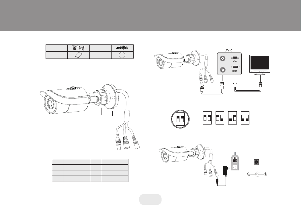
VTC-THB36R2F Components
Camera
User Manual
Screws
Drill Template
Overview
2
1
3 4
Video Connection
Connect the BNC video connector to a BNC cable, then to a DVR.
Monitor
Video
Video Output Mode Switch:
Select the desired video mode using the dip switches contained
within the on-cable Output Mode Switch as follows:
ON
ON
1
2
Power Connection
Connect the power connector to a regulated 12 VDC power adaptor.
ON
1
1
2
2
AHD
HD-TVI
ON
ON
1
1
2
2
CVBS
CVI
5
1
2
3
4
Lens
Sun Shield
Mount Lock
Mount Base
BNC Video Output
5
Output Mode Switch
6
7
Power Cable
76
12VDC
Power
3
Page 4
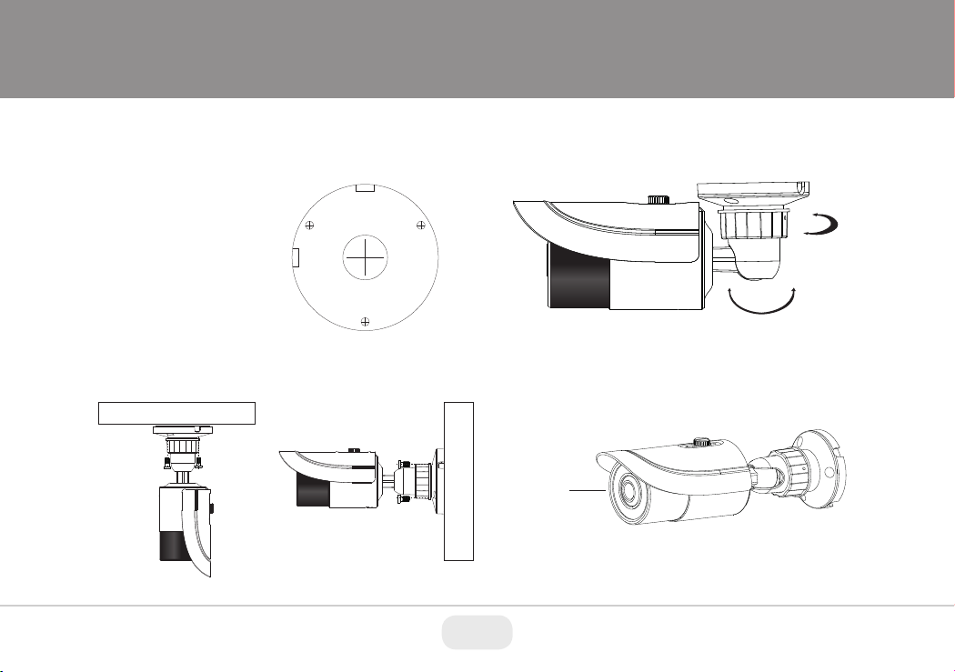
Installation
Before you begin, please make sure that the wall or ceiling is strong
enough to withstand 3 times the weight of the camera. The mounting
steps are as follows:
1. Attach the drill template to
the place where you want to
install the camera, then drill
3 screw holes and 1 cable
hole (if you want to route the
cables through the mounting
base) according to the drill
template
3. Loosen the mount lock to adjust the Pan and Tilt of the camera, then
tighten the mount lock to secure the viewing angle adjustments.
360° Pan
90° Tilt
2. Route the cables and connect the power & video cables, then
secure the mounting base to the ceiling or wall with screws.
Ceiling Mounted
Wall Mounted
4. Carefully remove the protective film from the lens to complete the
installation.
Protective
Lens Film
4
Page 5
VTC-THT24R2F Components
Camera
Manual
Screws
Hex Wrench
Mounting Plate
Rubber Plug
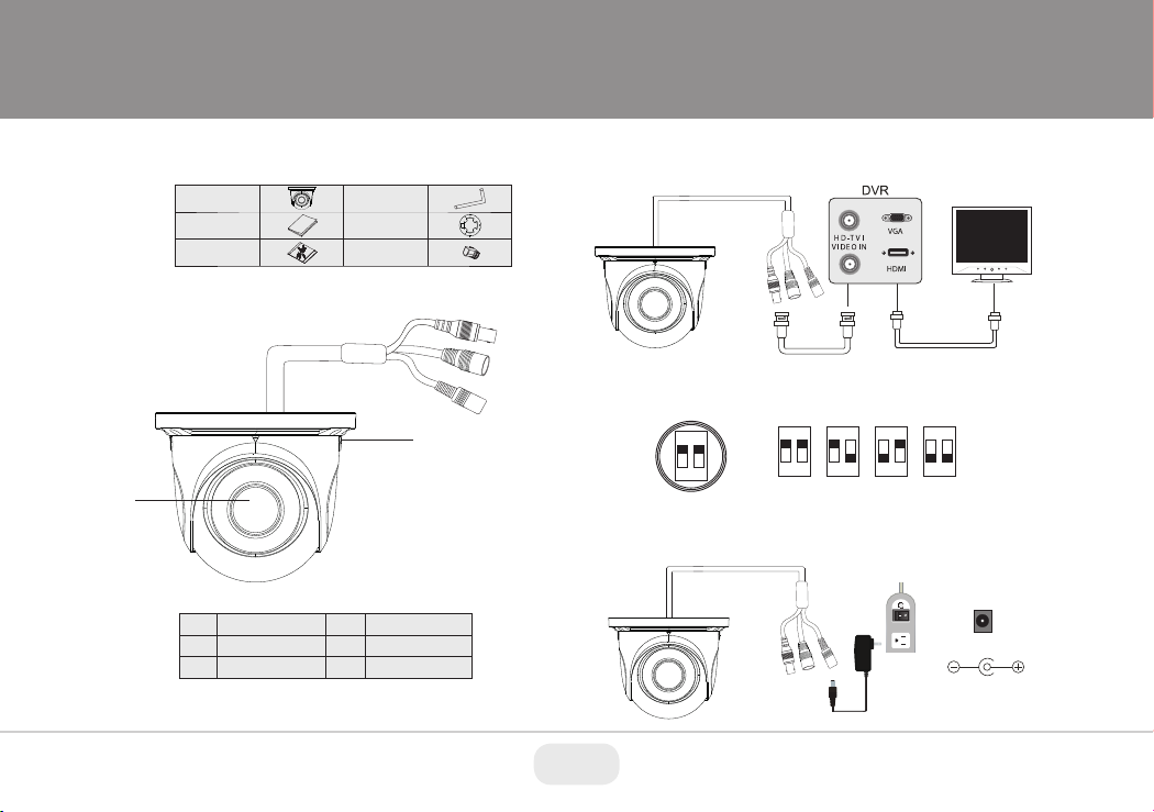
Overview
2
1
Video Connection
Connect the BNC video connector to a BNC cable, then to a DVR.
Monitor
3
4
5
Video Output Mode Switch:
Select the desired video mode using the dip switches contained
within the on-cable Output Mode Switch as follows:
ON
1
2
Power Connection
Connect the power connector to a regulated 12 VDC power adaptor.
Video
ON
ON
1
1
2
2
AHD
HD-TVI
ON
ON
1
1
2
2
CVBS
CVI
1
2
3
Lens
Lock Screws
BNC Video Output
Output Mode Switch
4
5
Power Cable
12VDC
Power
5
Page 6

Installation
Before you begin, please make sure that the wall or ceiling is strong
enough to withstand 3 times the weight of the camera. The mounting
steps are as follows:
1. Attach the drill template to
the place where you want to
install the camera, then drill
3 screw holes and 1 cable
hole (if you want to route the
cables through the mounting
base) according to the drill
template
.
2. Route the cables and
connect the power & video
cables, then secure the
mounting base to the ceiling
or wall with screws.
3. Loosen the lock screws, then
adjust the camera to obtain
the optimium viewing angle.
Confirm the correct viewing
angle with a monitor. Next
insert the rubber plug.
Rubber Plug
4. Tighten the lock screws to secure the viewing angle adjustments.
5. Carefully remove the protective film from the lens to complete the
installation.
Protective
Lens Film
6
Page 7

VTD-THD16R2F Components
Camera
Manual
Drill Template
Screws
Hex Wrench
Video Connection
Connect the BNC video connector to a BNC cable, then to a DVR.
Monitor
Overview
1
2
3
Mounting Base
Dome Cover
BNC Video Output
1
2
Output Mode Switch
4
5
Power Cable
Video
Video Output Mode Switch:
3
4
5
Select the desired video mode using the dip switches contained
within the on-cable Output Mode Switch as follows:
ON
ON
1
2
Power Connection
Connect the power connector to a regulated 12 VDC power adaptor.
ON
1
1
2
2
AHD
HD-TVI
ON
ON
1
1
2
2
CVBS
CVI
12VDC
Power
7
Page 8

Installation
Before beginning installation, make sure that the wall or ceiling is
strong enough to withstand 3 times the weight of the camera. The
mounting steps are as follows:
1. Attach the drill template to
the place where you want to
install the camera, then drill
the screw holes and 1 cable
hole according to the drill
template.
4. Adjust the Three-axis camer bracket to obtain the optimium
viewing angle.
Pan: 0°~240°
2. Loosen the screws to open
the lower dome and then
loosen the lock screw to
remove the mounting base.
3. Route the cables and
connect the power & video
cables, use the rubber plug
to fill the gap of the mounting
base. then secure the
mounting base to the ceiling
or wall with screws.
Rubber Plug
Rotation: 0°~220°
5. Install the dome bubble on
the camera with the screws,
then carefully remove the
protective film to complete
the installation.
8
Tilt: 0°~68°
Page 9

VTD-THMD2RF Components
Camera
Manual
Drill Template
Screws
Hex Wrench
Video Connection
Connect the BNC video connector to a BNC cable, then to a DVR.
Monitor
Overview
1
2
3
Mounting Base
Dome Cover
BNC Video Output
1
2
Output Mode Switch
4
5
Power Cable
Video
Video Output Mode Switch:
3
4
5
Select the desired video mode using the dip switches contained
within the on-cable Output Mode Switch as follows:
ON
ON
1
2
Power Connection
Connect the power connector to a regulated 12 VDC power adaptor.
ON
1
1
2
2
AHD
HD-TVI
ON
ON
1
1
2
2
CVBS
CVI
12VDC
Power
9
Page 10

Installation
Before beginning installation, make sure that the wall or ceiling is
strong enough to withstand 3 times the weight of the camera. The
mounting steps are as follows:
1. Attach the drill template to
the place where you want to
install the camera, then drill
the screw holes and 1 cable
hole according to the drill
template.
2. Loosen the screws to open
the lower dome and then
loosen the lock screw to
remove the mounting base.
3. Route the cables and
connect the power & video
cables, use the rubber plug
to fill the gap of the mounting
base. then secure the
mounting base to the ceiling
or wall with screws.
4. Before adjusting the three-axis camera mount, preview the
camera on a monitor, then adjust as necessary achieve the
optimum viewing angle.
Pan: 0°~360°
Rotation: 0°~350°
5. Install the dome bubble on the camera with the included screws,
then carefully remove the protective film to complete the
installation.
10
Tilt: 0°~70°
Page 11

Camera OSD Menu
The Transcendent 4-in1 camera series must be connected to a DVR
which supports HD-TVI/AHD video signal input and COC protocol to
access the OSD setup menu. Different DVRs manufacturers may have
different modes of menu operation.
The Following image will pop-up when you left click once on the
image when using Transcendent HDA DVR's.
You will see the following interface by clicking the PTZ button.
Click on the OSD tab and then click on the camera menu
button.
You can select the menu by clicking (U) or (D) key on the
direction area. Click (L) or (R) key to select the menu on the
left. The menu with arrow icon which means it has sub-menu. You
can select the menu and click the Enter Button to enter the
sub-menu. to return to previous screen, arrow down to Return and
click Enter Button. To Exit menu arrow down to Exit and click Enter
Button.
11
Page 12

VTC-THB36R2F Specifications
Preliminary Specifications:
VTC-THB36R2F
Transcendent 2.1 Megapixel Indoor/Outdoor 4-IN-1
HDA Bullet Camera w/36 IR LED Illumination
Preliminary Specifications:
VTD-THD16R2F
Transcendent 2.1 Megapixel Indoor/Outdoor 4-IN-1 HDA Vandal
Dome Camera w/16 High Power Covert IR LED Illumination
Image Sensor
Signal System
Effective Pixels
Resolution
Video Output
Frame Rate
Lens
Day/Night
Min. IIIumination
IR LEDs
IR Distance
S/N Ratio
WDR
Defog
Digital Noise Reduction (DNR)
White Balance
BLC
Up the COAX Control (COC)
Transmission Distance
Power Input
Power Consumption (12VDC)
Weather Resistance
Operation Conditions
Weight
Dimensions
1/2.8” 2.1 Megapixel Progressive Scan CMOS Sensor with Advanced Starlight Technology
Up to 1500’ (Depending on cable characteristics & integrity)
PAL/NTSC
1920 x 1080
HD-TVI / AHD / CVI: 2.1 MegaPixel / CVBS: 960H
HD-TVI / AHD / CVI / CVBS (Selectable)
30fps
2.8 or 3.6mm Fixed Lens Options
True Day/Night by ICR
Color: 0.001 lux@F1.2, AGC ON / B/W: 0 lux (with IR ON)
36 Dynamic Intensity LEDs
120’
≥52dB (AGC Off)
True WDR
YES
3D-DNR
Auto (AWB)
YES
YES
12VDC
IR On: 120mA / IR Off: 360mA
IP66
-4~122 / 10%~90% Humidity
20.81 oz. / 1.30 lbs. / 590g
3.43 x 8.62” (87mm x 219mm) Dia x L
VTD-THD16R2F Specifications
Image Sensor
Signal System
Effective Pixels
Resolution
Video Output
Frame Rate
Lens
Day/Night
Min. IIIumination
IR LEDs
IR Distance
S/N Ratio
WDR
Defog
Digital Noise Reduction (DNR)
White Balance
BLC
Up the COAX Control (COC)
Transmission Distance
Power Input
Power Consumption (12VDC)
Resistance Rating
Operation Conditions
Weight
Dimensions
12
1/2.8” 2.1 Megapixel Progressive Scan CMOS Sensor with Advanced Starlight Technology
Up to 1500’ (Depending on cable characteristics & integrity)
PAL/NTSC
1920 x 1080
HD-TVI / AHD / CVI: 2.1 MegaPixel / CVBS: 960H
HD-TVI / AHD / CVI / CVBS (Selectable)
30fps
2.8 or 3.6mm Fixed Lens Options
True Day/Night by ICR
Color: 0.001 lux@F1.2, AGC ON / B/W: 0 lux (with IR ON)
16 Dynamic Intensity LEDs
65’
≥52dB (AGC Off)
True WDR
YES
3D-DNR
Auto (AWB)
YES
YES
12VDC
IR Off: 120mA / IR On: 480mA
IP66 / IK10
-4~122 / 10%~90% Humidity
21.34 oz. / 1.33 lbs. / 605g
4.57” x 3.58” (116mm×91mm) Dia x H
Page 13

Preliminary Specifications:
VTD-THMD2RF-2
Transcendent 2.1 Megapixel Indoor/Outdoor 4-IN-1
HDA Dome Camera w/10 IR LED Illumination
VTD-THMD2RF-2 Specifications
Preliminary Specifications:
VTC-THT24R2F
Transcendent 2.1 Megapixel Indoor/Outdoor 4-IN-1
HDA Turret Camera w/24 IR LED Illumination
Image Sensor
Signal System
Effective Pixels
Resolution
Video Output
Frame Rate
Lens
Day/Night
Min. IIIumination
IR LEDs
IR Distance
S/N Ratio
WDR
Defog
Digital Noise Reduction (DNR)
White Balance
BLC
Up the COAX Control (COC)
Transmission Distance
Power Input
Power Consumption (12VDC)
Resistance Rating
Operation Conditions
Weight
Dimensions
1/2.8” 2.1 Megapixel Progressive Scan CMOS Sensor with Advanced Starlight Technology
Up to 1500’ (Depending on cable characteristics & integrity)
PAL/NTSC
1920 x 1080
HD-TVI / AHD / CVI: 2.1 MegaPixel / CVBS: 960H
HD-TVI / AHD / CVI / CVBS (Selectable)
30fps
2.8mm Fixed Iris Lens
True Day/Night by ICR
Color: 0.001 lux@F1.2, AGC ON / B/W: 0 lux (with IR ON)
10 Dynamic Intensity LEDs
65’
≥52dB (AGC Off)
True WDR
YES
3D-DNR
Auto (AWB)
YES
YES
12VDC
IR Off: 120mA / IR On: 480mA
IP66 / IK10
-4~122 / 10%~90% Humidity
12.31 oz. / 0.77 lbs. / 349g
4.33” x 2.28” (110 × 58mm) Dia x H
VTC-THT24R2F Specifications
Image Sensor
Signal System
Effective Pixels
Resolution
Video Output
Frame Rate
Lens
Day/Night
Min. IIIumination
IR LEDs
IR Distance
S/N Ratio
WDR
Defog
Digital Noise Reduction (DNR)
White Balance
BLC
Up the COAX Control (COC)
Transmission Distance
Power Input
Power Consumption (12VDC)
Weather Resistance
Operation Conditions
Weight
Dimensions
13
1/2.8” 2.1 Megapixel Progressive Scan CMOS Sensor with Advanced Starlight Technology
Up to 1500’ (Depending on cable characteristics & integrity)
PAL/NTSC
1920 x 1080
HD-TVI / AHD / CVI: 2.1 MegaPixel / CVBS: 960H
HD-TVI / AHD / CVI / CVBS (Selectable)
30fps
2.8 or 3.6mm Fixed Lens Options
True Day/Night by ICR
Color: 0.001 lux@F1.2, AGC ON / B/W: 0 lux (with IR ON)
24 Dynamic Intensity LEDs
65’
≥52dB (AGC Off)
True WDR
YES
3D-DNR
Auto (AWB)
YES
YES
12VDC
IR Off: 120mA / IR On: 480mA
IP66
-4~122 / 10%~90% Humidity
13.05 oz. / 0.82 lbs. / 370g
3.43” x 4.25” (87 × 108mm) Dia x H
Page 14

14
Page 15

TRANSCENDENT MOUNTS ALSO
AVAILABLE FOR 4-IN-1 CAMERAS!
VT-TJB01
Optional Junction Box for
Cable Management for use
with all Transcendent Bullet
and Turret Style Cameras
(VTC-THB36R2F / VTCTHT24R2F)
VT-TWMT3
Optional Wall Mount for use
with most Transcendent
Fixed Domes and Turrets
(VTC-THT24R2F / VTDTHD16R2F)
15
VT-TJB03A
Optional Junction Box for Cable
Management for use with Select
Transcendent Vandal Dome
Cameras (VTD-THD16R2F)
Page 16

28492 CONSTELLATION ROAD VALENCIA, CA 91355
WWW.VITEKCCTV.COM
Version 3.0
September 2018
 Loading...