

Page 1
VTD-T4D6HR2MD
2.1 Megapixel 4-IN-1 HD-TVI /
AHD / CVI / CVBS Motorized
Varifocal WDR Dome Camera
with IR LED Illumination
VITEK
VITEK
FEATURES
• 1/2.9” 2.1 Megapixel Sony® Exmor™ Progressive Scan
CMOS Sensor
• 30fps live view @ 1920 x 1080p
• True Day/Night by IR Cut Filter
• HD-TVI / HD-CVI / AHD / 960H CVBS Video Output
(Selectable)
• Motorized 2.8~12mm MegaPixel IR Corrected Auto Focus
Varifocal Lens with CoC
• 6 Integrated High Power Dynamic IR LEDs with up to 165’
IR Range
• 3D-DNR Noise Reduction
• True Wide Dynamic Range (WDR)
• 16:9 Video format
• IP66 Weather Resistance
• Supports Up The COAX Control (CoC)
• Over 1500’ HD Video Transmission (Depending on cable
characteristics and integrity)
• 12VDC / 24VAC Dual Voltage Operation
• 3 Year Warranty
Page 2
Safety Precaution
To prevent electrical shock and risk of fire hazards, do not expose this unit
to rain or moisture and only use specified power source..
CAUTION: TO REDUCE THE RISK OF ELECTICAL
SHOCK, DO NOT REMOVE COVER (OR BACK).
NO USER SERVICEABLE PARTS INSIDE.
REFER SERVICING TO QUALIFIED SERVICE PERSONNEL
The symbol is intended to alert the user to the presence of uninsulated
"dangerous voltage" within the product's enclosure that may be of
sufficient magnitude to constitute a risk of electrical shock.
The symbol is intended to alert the user to the presence of important
operating and maintenance (servicing) instructions in the literature
accompanying the unit.
Warning :
This equipment has been tested and found to comply with the limits for a Class
A digital device, pursuant to part 15 of the FCC Rules. These limits are designed
to provide reasonable protection against harmful interference when the equipment
is operated in a commercial environment. This equipment generates, uses, and
can radiate radio frequency energy and, if not installed and used in accordance with
the instruction manual, may cause harmful interference to radio communications.
Operation of this equipment in a residential area is likely to cause harmful
interference in which case the user will be required to correct the interference at
their own expense.
Caution :
Any changes or modifications in construction of this device which are not expressly
approved by the party responsible for compliance could void the user's authority
to operate the equipment.
Main power quality should be that of a typical commercial environment. If the user
of the model requires continued operation during power interruptions, it is
recommended that the device be powered from an uninterruptible power supply
(UPS).
2 3
Page 3
Installation
1) Disconnect power before installation.
2) Confirm proper 12VDC or 24VAC power supply is used to prevent
damage to the camera.
3) Do not use in an environment beyond the boundaries of the
specifications.
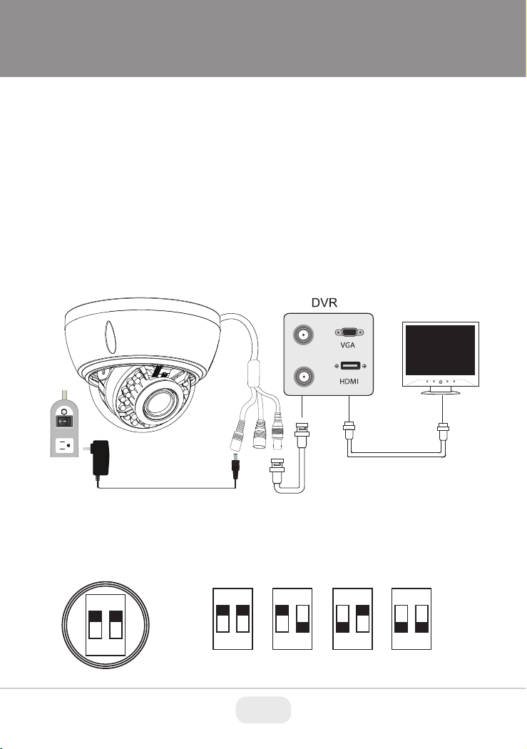
Power & Video Connections
Connect the HD-TVI Video or AHD/CVBS video connector to a BNC
patch cable, then to a DVR. Next connect the power connector to a
12VDC or 24VAC power adaptor.
Monitor
12VDC / 24VAC Power
Video
Video Output Mode Switch:
Select the desired video mode using the dip switches
contained within the on-cable Output Mode Switch as follows:
ON
1
2
ON
1
AHD
2
ON
1
HD-TVI
ON
2
2
1
CVI
3
ON
1
CVBS
2
Page 4

OSD Instruction
EXIT
SCANNING HALF
1. IRIS
IRIS ELC
2-MOTOR
EXPOSURE
BACKLIGHT OFF
DAY&NIGHT
COLOR
DNR LOW
IMAGE
MOTION OFF
SYSTEM
2. 2-MOTOR
IRIS ALC
2-MOTOR
EXPOSURE
BACKLIGHT OFF
DAY&NIGHT
COLOR
DNR LOW
IMAGE
MOTION OFF
SYSTEM
EXIT
AF MODE AUTO
ONE PUSH AF ON
SYNC TDN ON
INITIAL ON
RETURN
IRIS
Electronic Ligh t Control (ELC)
When using a fi xed or manual ir is lens, the
camera's ELC can adjust for moderate changes in
illumination levels. While it is fine for indoor
applications in fixed illumination conditions, a
fixed i ris and ELC circuitry cannot approach the
range o f illumi nation us able wi th an auto-iris lens
and A LC circuitry.
Automa tic Lig ht Contr ol (ALC)
When using an auto-iris lens, the ALC circuitry
samples the illumination level and automatically
adjusts the iris to cr eate the proper sized aperture
for proper exposure.
2-M OTOR
AF (Auto Focus))
Choose between A uto focus a nd Manual fo cus.
SCANNING
When Le ns scans Half or Full for foc using.
SYNC TDN
Lens scans Half or Full for focus ing.
when swi tching from Day to Ni ght or Night to Day.
INITIAL
Sets lens parameters from close to far.
Adjust lens
4 5
Page 5

3. EXPOSURE
EXPOS URE
POS 4
RETUREN
RETURN
IRIS ELC
2-MOTOR
EXPOSURE
BACKLIGHT OFF
DAY&NIGHT
COLOR
DNR LOW
IMAGE
MOTION OFF
SYSTEM
EXIT
4. BACKLIGHT
IRIS ELC
2-MOTOR
EXPOSURE
BACKLIGHT BLC
DAY&NIGHT
COLOR
DNR LOW
IMAGE
MOTION OFF
SYSTEM
EXIT
BRIGHTNESS
SHUTTER MANUAL
SENS UP X2
AGC
H-POS 6
V-
H-SIZE 5
V-SIZE 3
BRIGHTN ESS
0-20 selectable.
SHUTT ER
AUTO/FLICKER/MANUAL
MANUAL MODE
1/25、1/50、1/100、1/200、1/400、1/800、1/1600、
1/3200、1/6400、1/12800、1/25600、1/30000,
selectable.
AUTO
DEBLURE/NORMAL., s electable.
SENS-UP
OFF、X2、X4、X8、X16、X32 selectable.
AGC
0-20 selectable
BACKLIGH T
BACKLIGH T
OFF/HLC/BLC/WD R, used in different environment.
HLC (High Light Compensation)
Cuts ou t the bright area with a mask and excludes it
from compensation..
LEVEL (0~20)
Sets the H LC level. It det ermines the video level that
starts cutting ou t. Lower set ting starts the cut out at a
lower light level. The cut out area is masked with
selected color.
COLOR
Select mask color from 9 colors. Black, White,
Yellow, Cyan, Green, Magenta, Red, Blue and
Customize.
BLC (Back light Compensation)
Compensates the video i mage by cutting out the
bright areas with a mask or adjusting the contrast of
the vid eo. This function is used to brighten an image
in the f oregrou nd with a bright light area behind it
such as sunlight, li miting t he affec t of silho uette. BLC
has a target window for compensation and its size
and position can be s et by H-POS, V-POS, H-S IZE and
V-SIZE.
H-POS, V-P OS
Sets the position of BLC area to move vertically and
horizontally.
H-SIZE, V-SIZE
Sets the size of BLC area to move vertically and
horizontally.
WDR:
HIGH/ MIDDLE/ LOW level, selectable, 30fps.
Note: CVBS will stop when WDR is turned o n.
5
Page 6

5. D AY& NIGHT
IRIS ELC
2-MOTOR
EXPOSURE
BACKLIGHT OFF
Day& NIGHT EXTERN
COLOR
DNR LOW
IMAGE
MOTION OFF
SYSTEM
EXIT
6. COLOR
IRIS ELC
2-MOTOR
EXPOSURE
BACKLIGHT OFF
DAY&NIGHT
COLOR
DNR LOW
IMAGE
MOTION OFF
SYSTEM
EXIT
ANTI-SAT.
EXTERN SW NONE
D>N THR ES
N>D THR ES
DE LAY LOW
RETURN
WB MANUAL
COLOR GAIN
RETUEN
DAY & NIGHT
Switch settings of Day and Night mode.
AUTO
Used when DAY or NIGHT is determined by light
level through t he lens.
COLOR
The camera is always in COLOR mode. DAY/NIGHT
is disabled and o utputs color video
B&W
The camera is always in B/W mode. Forcibly
removes IR c ut filter and switches to B/W regardless
of light level.
EXTER N
DAY or NIGHT is determined by the built-in light
photo sensor for camera s with b uilt-in IR LEDS.
ANTI-S AT
Sets the anti saturation level 0~20. Setting high
level avoids saturation but the corners will be
darker accordingl y.
D>N THR ES & N>D THRES
Sets the light level for switchi ng from Day to Night /
Night to day.
DE LAY
Is time i n seconds w hile ca mera mai ntains its status
before Day to Night / Night to Day switchin g. (Only
available when mode is AUTO or EXTERN).
COLOR
AWB (Auto White Ba lance)
Automatically tra cks the cha nges of color
temperature and contin uously adjusts the white
balance. AUTO, AUTOext, PRESET and MANUAL
modes are available.
AUTO
Optimiz ed for Indoor installation a nd comp ensates
AWB for low color temperat ure such as
incandes cent li ghts.
AUTOex t
Optimized for outdoor sunlight applications and
compens ates AWB for high color te mperature suc h
as sunli ght.
PRESET
AWB is performed only whenever b utton is pressed.
MANUAL
White balance is fixed to the settings by
Color-Temperature Red-GAIN and Blue-GAIN. It can
be used only when the color temper ature does not
va ry.
6 7
Page 7

7. D NR
DNR
o qual ity can be less in normal e nvironme nts.
IRIS ELC
2-MOTOR
EXPOSURE
BACKLIGHT OFF
DAY&NIGHT
COLOR
DNR LOW
IMAGE
MOTION OFF
SYSTEM
EXIT
8. IMAGE
IRIS ELC
2-MOTOR
EXPOSURE
BACKLIGHT OFF
DAY&NIGHT
COLOR
DNR LOW
MOTION OFF
SYSTEM
EXIT
IMAGE
SHARPNESS
GAMMA 0.55
ORIENTATION NORMAL
FLIP OFF
ACE OFF
DEFOG ON
PR IVA CY
RETURN
3D-NR ( Digital Noise Reduction)
DNR function improves picture quality by filtering
out signal noise which is generated under low light
conditions. Set off, low, middle or high level. 3DNR
(3-dimensional n oise red uction) whic h reduces
noise by multi frames. It is effective in low light. Set
to high will reduce the most noise but the image
will be less sharp and a tailing effect might occur.
IMAGE
SHARPNESS
Sets the Sharpness level 0~10. Increases or
decreases the s harpness of the pi cture. Too much
sharpnes s can make image harsh and show more
noise as well as line flicker at the edge of objec t in
the picture
GAMMA
Used to adjustmen t the mo nitor GAMMA value
0.45/0.55/0.65/0.75 selectable.
ORIENTATION
NORMAL / MIRROR / FLIP / MIRR OR_V.
ACE
Improves the visibility for the bright areas and the
dark areas by co mpensa ting the video gai n. Care
should be taken to select low, middle or high level,
because video may lose its quality in some
environments by over compensation. Video noise
can be increased in the dark area accordingly
DEFOG
Enhance foggy video accordi ng to sta tus of sc ene.
Vide
PRIVA CY
Set ON/OFF for enabling/disabling PRIVACY mask.
16 privacy areas are available and each area is
programmable in size, color, position and
transparency.
ZONE N UM
Selects mask zone number from 0 to 16 to b e
adjust.
‘
ZONE DISP
Displa ys OFF/ON for the mask ar ea which you
selected.
H-POS, V-P OS
Adjusts the mas k area H, V positi on whic h you
selected.
TRANS
Selects transparency rate for the mask area from 0
to 3
7
Page 8

9. M OTION
IRIS ELC
2-MOTOR
EXPOSURE
BACKLIGHT OFF
DAY&NIGHT
COLOR
DNR LOW
IMAGE
MOTION ON
SYSTEM
EXIT
DET WINDOE
DET TONE 2
MORECT FILL OFF
SENSITIVITY
MOTION OSD OFF
TEXT AL ARM OFF
SIGNAL OUT OFF
RETURN
MOTIO N
3 motion detection areas are available a nd each
area is programmable in size and location.
Motion c an be detected in the area and
displays the results in blocks and/or a text
message
DET WINDOW
WINDOW Z ONE : Set t he detectio n zone
number from 0 to 3.
H-POS
0-60 horizontal starting point.
V-POS
0-34 vertical ending point.
H-SIZE
0-60 horizontal ending point.
V-SIZE
0-34 vertical ending point.
DET ZON E
Sets the detectio n zone 0 to 4 displ ay types
which wi ndow use se tting ON.
0) Set 100% opacity level of video background
except detection window zone.
1) Set 50% opacity level of video background
except detection window zone.
2) Set 25% opacity level of video background
except detection window zone.
3) Video background image is same as
detection w indow zone.
4) Detection wi ndow zone is display ed with box
line
MDRECT FILL
Sets the motio n display type w hen motio n is
detected in video. Setting ON will display a red
solid box type. Setting OFF will display a red
outline box type
Sensit ivity
Sets the detection sensitivity for motion (0~10).
Higher valu es increases the sensitivit y to detect
motion. Too low of a value will cause the erratic
detection by tree leaves or light level changes
MOTION OSD
Set ON or OFF to display motion results.
TEXT ALARM
Setting ON enables to display a text mess age
“WINDOWS MOVING!!” or icon when motion
is detected.
8 9
Page 9

10. SYSTEM
SYST EM
IRIS ELC
2-MOTOR
EXPOSURE
BACKLIGHT OFF
DAY&NIGHT
COLOR
DNR LOW
IMAGE
MOTION OFF
SYSTEM
EXIT
COM.
IMAGE RANGE USER
COLOR S PACE HD -CbCr
FRAME RATE 1080P_30FPS
Monitor 0-3
FR EQ PAL
CVBS ON
LANGUAGE CHN[S]
COLOR BAR
CAM TITLE OFF
RESET ON
RETURN
COM.
RS-485 Communication setting ID: 0-255,
BAUDRATE: 2400/4800/9600/57600/115200
selectable.
IMAGE RANGE
USER/FULL/COMP, the OFFSET of USER: 0 -32.
COLOR SPACE
HD-CbCr、YUY、 SD-Cb Cr.
FRAME RA NGE
1080P/720P_ (25fps/30fps), selectable.
Monitor
0-3, choose a different screen style.
FREQ
NT SC/ PAL.
CVBS
ON/OFF.
LAUGUAGE
Multiple languages CHN [S], CH N,EN、JPN
KOR、I TA
COLOR BAR
OFF/ON, used in color contrast test (col or bar
on screen).
CAM TITLE
Using the OSD button s elect letters by
pushing button up, down, left or right.
RESET
Hold OSD button for 10 sec onds to r eset
camera
9
Page 10

CONSIDER THESE OTHER GREAT
TRANSCENDENT PRODUCTS!
VT-TTAR Series
Transcendent Series 4, 8, 16, and 32 Channel 5-In-1 HD-TVI / AHD /
CVI / 960H / IP Digital Video Recorders
• 4, 8, 16, or 32 Channel HD-TVI / AHD / CVI / CVBS BNC Inputs + IP Camera Support
• 1-Channel IP Camera Support (VT-TTAR410 / VT-TTAR810) / 4-Channel IP Camera
Support (VT-TTAR1620 / VT-TTAR3280)
• 960fps @ 720p & 1080P-Lite / 480fps @ 1080p Recording
• Simple plug and play, point-to-point connection from camera to DVR
• H.264 Compression
• HDMI, VGA, and BNC (Spot) Video Outputs
• 2-Way Audio
• PTZ Control over RS-485
• 16 Alarm inputs / 4 Alarm Output
• Pentaplex: Live Display / Record / Playback / Backup / Remote Access
• 1 Internal SATA2/SATA3 HDD Slot supporting up to 8TB (1 x 8TB HDD) (VT-TTAR410
/ VT-TTAR810) / 2 Internal SATA2/SATA3 HDD Slots supporting up to 16TB (2 x 8TB
HDD) (TTAR1620) / 8 Internal SATA2/SATA3 HDD Slots supporting up to 64TB (8 x
8TB HDD) Internal Storage (VT-TTAR3280)
• Applications for iOS & Android
• Remote Viewing over the Internet via Web Browser or LAN
• Mac OS® Client & CMS Central Management Software Included
• Supports both Dynamic and Static IP Addresses
• Control locally via USB Mouse, or with the Included IR Remote control
• 3 Year Warranty
10 11
Page 11

Detailed Specifications
Image Sensor
Signal System
Effective Pixels
Resolution
Video Output
Lens
Day/Night
Min. IIIumination
IR LEDs
IR Distance
DSS (Sens-Up)
S/N Ratio
WDR
Digital Noise Reduction (DNR)
White Balance
BLC
Defog
Privacy Mask
Motion Detection
Up the COAX Control (COC)
Transmission Distance
Power Input
Power Consumption (12VDC)
Power Consumption (24VAC)
Weather Resistance
Operation Conditions
Weight
Dimensions
1/2.9” 2.1 Megapixel Sony® Exmor™ Progressive Scan CMOS Sensor
PAL/NTSC
1920(H) × 1080(V)
HD-TVI / HD-CVI / AHD: 1080p/720p (2.1 MegaPixel) / CVBS: 960H
HD-TVI / HD-CVI / AHD / CVBS (Selectable)
Motorized 2.8~12mm MegaPixel IR Corrected Varifocal Lens
True Day/Night by ICR
0.001 Lux @ f2 (B/W) / 0.1Lux @ F2.0 (Color) / 0 Lux (IR ON)
6x High Power Dynamic IR LEDs
165’
OFF / X2 ~ X32
≥50dB (AGC Off)
True WDR
3D-DNR
Auto / Present / External / Manual
Adjustable
Adjustable
16 Programmable Areas
4 Programmable Areas
YES
Up to 1500’ (Depending on cable characteristics & integrity)
Dual Voltage: 12VDC / 24VAC
650mA (IR ON) / 220mA (IR OFF)
325mA (IR ON) / 110mA (IR OFF)
IP66
-4~122 / 10%~90% Humidity
17 oz. / 1.06 lbs. / 482g
4.72” x 3.41” x 4.72” (120 x 86.5 x 120mm)
Page 12

LIMITED PRODUCT WARRANTY
VITEK products carry a three (3) year limited warranty. VITEK warrants
to the purchaser that products manufactured by VITEK are free of any
rightful claim of infringement or the like, and when used in the manner
intended, will be free of defects in materials and workmanship for a
period of three (3) years, or as otherwise stated above, from the date of
purchase by the end user. This warranty is nontransferable and extends
only to the original buyer or end user customer of a VITEK Authorized
Reseller.
The product must have been used only for its intended purpose, and
not been subjected to damage by misuse, willful or accidental damage,
caused by excessive voltage or lightning.
The product must not have been tampered with in any way or the
guarantee will be considered null and void.
This guarantee does not affect your statutory rights.
Contact your local VITEK Reseller should servicing become necessary.
VITEK makes no warranty or guarantee whatsoever with respect to
products sold or purchased through unauthorized sales channels.
Warranty support is available only if product is purchased through a
VITEK Authorized Reseller.
28492 CONSTELLATION ROAD VALENCIA, CA 91355
WWW.VITEKCCTV.COM
Version 1.0
December 2017
 Loading...