

Vitek VTD-MVS1850-L35-B, VTD-MVS1850DN, VTD-MVS1850DN-B, VTD-MVS1850-L35, VTD-MS922DN User Manual
...Page 1
MIGHTY DOME
960H Cameras
750 TVL Dome Cameras Series
VITEK
• 1/3” 960H High Density Double Scan Sony CCD
• 750 TVL High Resolution
• WDR - Wide Dynamic Range (Selected Models)
• True Day/Night by ICR
• IR Corrected Lens Options Lens options: 2.8-10mm and
9-22mm
• XD-DNR (2D+3D DNR) Noise Reduction
• Polygon Masking with 15 Programmable Zones
• OSD (On Screen Display) for Camera Setup
• Flush or Surface mount with included adaptor
• Defog video enhancement processing
• Ultra Versatile Design with Infinity Ball Mount for Any
Viewing Angle
• UTC CONTROL - Serial Control over Coax
• Secondary Video Output (Cable Included)
• Optional UTP Interface Available
• Fully Gasket Sealed with an IP-68 Water tight NEMA Rating
(Vandal Resistant Versions)
• Optional Heater / Blower Options Available (Vandal
Resistant Versions)
• Standard (-40°F) and Extreme Cold (-60°F) Temperature
Kits Available (Vandal Resistant Versions)
• Available in Ivory or Black
• 12VDC / 24VAC Dual Voltage Operation
Page 2

TABLE OF CONTENTS
BOX CONTENTS .......................................................................... 2
INCLUDED ACCESSORIES ......................................................... 2
AVAILABLE MODELS/ACCESSORIES ........................................ 3
MIGHTY DOME LAYOUT .............................................................. 4
INSTALLATION ............................................................................. 5
JUNCTION BOX INSTALLATION .................................................. 6
CONNECTIONS ........................................................................... 7
LENS ADJUSTMENT .................................................................... 8
3-AXIS GIMBAL ADJUSTMENT.................................................... 9
WDR MIGHTY DOME FEATURES ............................................... 10
OSD MENU STARTUP / MENU TABLE ........................................ 10
1. Scene Select ........................................................................ 13
2. Picture Adjustment ............................................................... 20
3. Electronic Zoom.................................................................... 21
4. Digital Image Stabilization (DIS) ........................................... 21
5. Privacy Mask ........................................................................ 22
6. Motion Detection................................................................... 23
7. System Setting ..................................................................... 24
8. Language.............................................................................. 26
9. Version ................................................................................. 26
10. Maintenance ....................................................................... 27
11. Exit ...................................................................................... 28
HEATER/BLOWER SPECIFICATIONS ......................................... 28
INDOOR WDR DOME SPECIFICATIONS .................................... 29
VANDAL WDR DOME SPECIFICATIONS .................................... 30
INDOOR DAY/NIGHT DOME SPECIFICATIONS ......................... 31
VANDAL DAY/NIGHT DOME SPECIFICATIONS .......................... 32
IR DOME SPECIFICATIONS ........................................................ 33
DIMENSIONS ................................................................................ 34
OTHER PRODUCTS FROM VITEK ............................................. 35
OTHER PRODUCTS FROM VITEK ............................................. 36
WARRANTY .................................................................................. 37
1
Page 3

BOX CONTENTS
1) Mighty Dome Camera
2) Accessories
3) VT-MD-2VOC (Secondary Video Output Cable)
4) Instruction Manual & Mounting Template
INCLUDED ACCESSORIES
Torx Wrench - (Vandal & IR Versions Only)
Type #: T20
Length: 63mm / Diameter: 4mm
Qty: 1
Phillips head Screws - (Vandal & IR Versions Only)
For attaching the dome cover to the flush housing.
Type #: Phillips head M4x10
Length: 10mm / Diameter: 4mm
Qty: 4
Self Tapping Screws
For attaching the surface mount housing or the the flush
mount base
to a solid surface.
Type #: Phillips St4x30
Length: 30mm / Diameter: 4mm
Qty:4
Self Tapping Screws - (Indoor Version Only)
For attaching the dome cover to the flush housing.
Type #: Phillips St4x12
Length: 12mm / Diameter: 4mm
Qty: 4
Anchors
If necessary, use to help secure the self tapping screws.
Length: 30mm / Diameter: 7mm
Qty: 4
Secondary Video Output Cable for Mighty Domes:
VT-MD-2VOC
For viewing video image during installation.
Qty: 1
Mounting Template
Surface Mount
109.0
70.0
Mounting Template
Qty: 1
2
Page 4

AVAILABLE MODELS / ACCESSORIES
Indoor MIghty doMe ConfIguratIons:
VTD-MS2810DN: 960H - Indoor Effio-A Powered Day/Night Mighty Dome 750TVL Camera
w/2.8-10mm Lens, OSD, ICR and “Night Watch” DSS -12VDC/24VAC (Ivory or Black)
VTD-MS922DN: 960H - Indoor Effio-A Powered Day/Night Mighty Dome 750TVL Camera w/922mm Lens, OSD, ICR and “Night Watch” DSS -12VDC/24VAC
VTD-MS1850DN: 960H - Indoor Effio-A Powered Day/Night Mighty Dome 750TVL Camera
w/18-50mm Lens, OSD, Day Night w/ICR and “Night Watch” DSS -12VDC/24VAC -Special
Order (Call for Lead Time) (Available In Ivory or Black)
VTD-MS2810WDR: 960H - Indoor Effio-V Powered WDR Mighty Dome 750TVL Camera
w/2.8-10mm Lens, OSD, ICR and “Night Watch” DSS -12VDC/24VAC (Ivory or Black)
VTD-MS922WDR: 960H - Indoor Effio-V Powered WDR Mighty Dome 750TVL Camera w/922mm Lens, OSD, Day Night w/ICR and “Night Watch” DSS -12VDC/24VAC (Ivory or Black)
Vandal resIstant MIghty doMe ConfIguratIons:
VTD-MVS2810DN: 960H - Outdoor Vandal Proof Effio-A Powered Day/Night Mighty Dome
750TVL Camera w/2.8-10mm Lens, OSD, ICR and “Night Watch” DSS -12VDC/24VAC (Ivory or
Black)
VTD-MVS922DN: 960H - Outdoor Vandal Proof Effio-A Powered Day/Night Mighty Dome
750TVL Camera w/9-22mm Lens, OSD, ICR and “Night Watch” DSS -12VDC/24VAC (Ivory or
Black)
VTD-MVS1850DN: 960H - Outdoor Vandal Proof Effio-A Powered Day/Night Mighty
Dome 750TVL Camera w/18-50mm Lens, OSD, Day Night w/ICR and “Night Watch” DSS
-12VDC/24VAC - Special Order (Call for Lead Time) (Available In Ivory or Black)
VTD-MVS2810/L35: 960H - Outdoor Vandal Proof Effio-A Powered IR Mighty Dome 750TVL
Camera w/2.8-10mm Lens, 35 IR LED’s, OSD, Day Night w/ICR and “Night Watch” DSS
-12VDC/24VAC (Available In Ivory or Black)
VTD-MVS922/L35: 960H - Outdoor Vandal Proof Effio-A Powered IR Mighty Dome 750TVL
Camera w/9-22mm Lens, 35 IR LED’s, OSD, CR and “Night Watch” DSS -12VDC/24VAC (Ivory
or Black)
VTD-MVS1850/L35: 960H - Outdoor Vandal Proof Effio-A Powered IR Mighty Dome 750TVL
Camera w/18-50mm Lens, 35 IR LED’s, OSD, Day Night w/ICR and “Night Watch” DSS
-12VDC/24VAC - Special Order (Call for Lead Time) (Available In Ivory or Black)
VTD-MVS2810WDR: 960H - Outdoor Vandal Proof Effio-V Powered WDR Mighty Dome
750TVL Camera w/2.8-10mm Lens, OSD, ICR and “Night Watch” DSS -12VDC/24VAC (Ivory or
Black)
VTD-MVS922WDR: 960H - Outdoor Vandal Proof Effio-V Powered WDR Mighty Dome
750TVL Camera w/9-22mm Lens, OSD, /ICR and “Night Watch” DSS -12VDC/24VAC (Ivory or
Black)
optIonal Mounts & aCCessorIes:
1. VT-MD-HB24: Heater/Blower Kit (Vandal Resistant Models)
2. VT-MD-UTP: Unshielded Twisted Pair Transceiver Built-In
3. VT-MD/FMP: Flush Mount Plate for installation in drop ceilings or can be used as cover
plate when using 4S Junction Box
4. VT-MD/PLMT: Mighty Dome Pole Mount Adapter - Requires VT-MD/WMT Wall Mount
5. VT-MD/CMT: Mighty Dome Ceiling/Pedestal Mount (Can be extended if necessary)
6. VT-MD/CNMT: Mighty Dome Corner Mount Adapter - Requires VT-MD/WMT Wall Mount
7. VT-MD/WMT: Mighty Dome Wall Mount (Available In Ivory or Black)
1. 2. 3. 4. 5. 6. 7.
3
Page 5
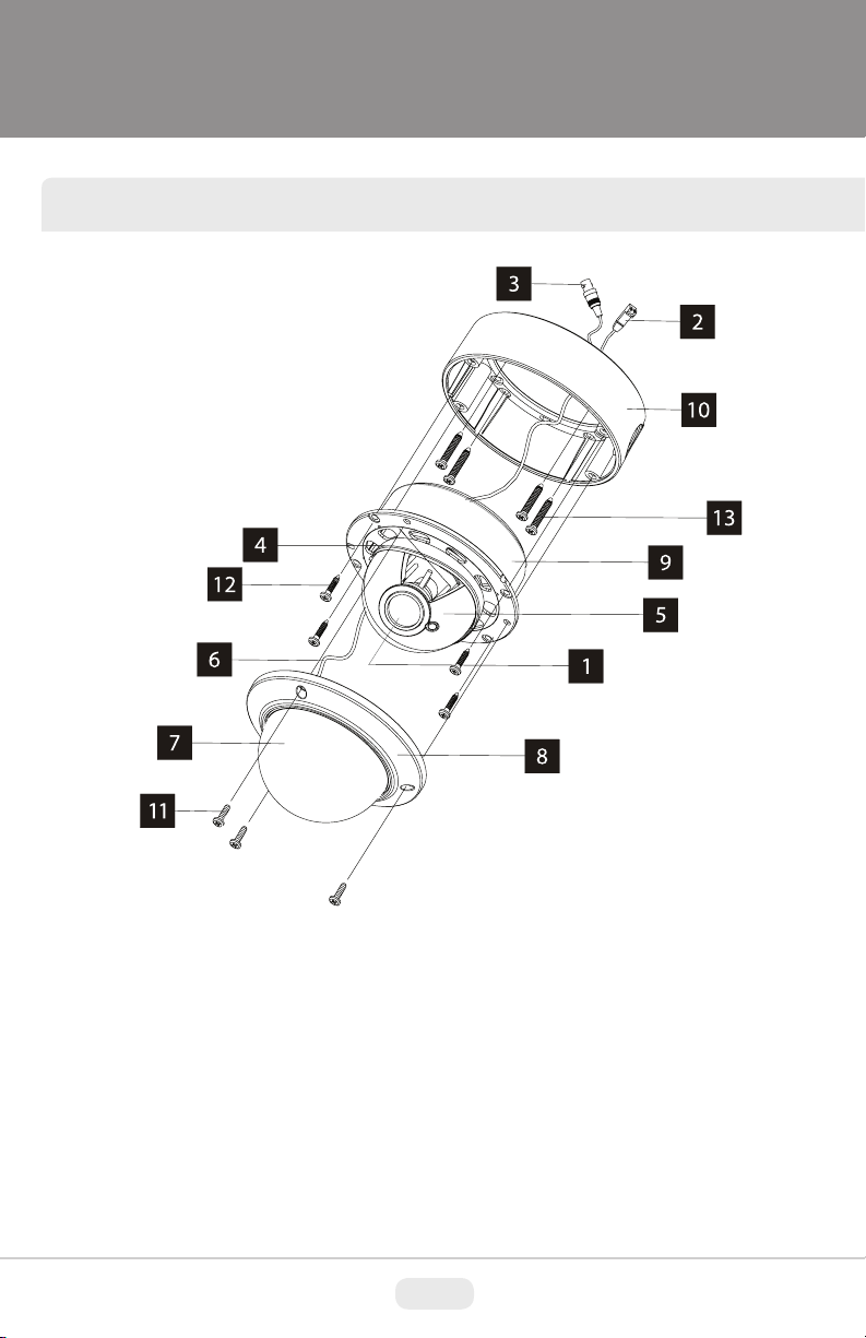
MIGHTY DOME LAYOUT
1) Lens
2) Power Input Connector(12VDC /
24VAC)
3) Video Output Connector - BNC
4) Camera Holder and 2nd Video
output
5) Ball with the Camera Assembly
6) Safety Wire
7) Bubble
8) Dome Cover Ring
9) Flush Mount Base
10) Surface Mount Base
11) Assembly Screws - Torx M4x9
(Vandalproof)
12) Assembly Screws - Phillips
ST4x12 (Indoor) / Phillips M4x10
(Vandalproof / IR)
13) Mounting Screws - Phillips
ST4x30
4
Page 6
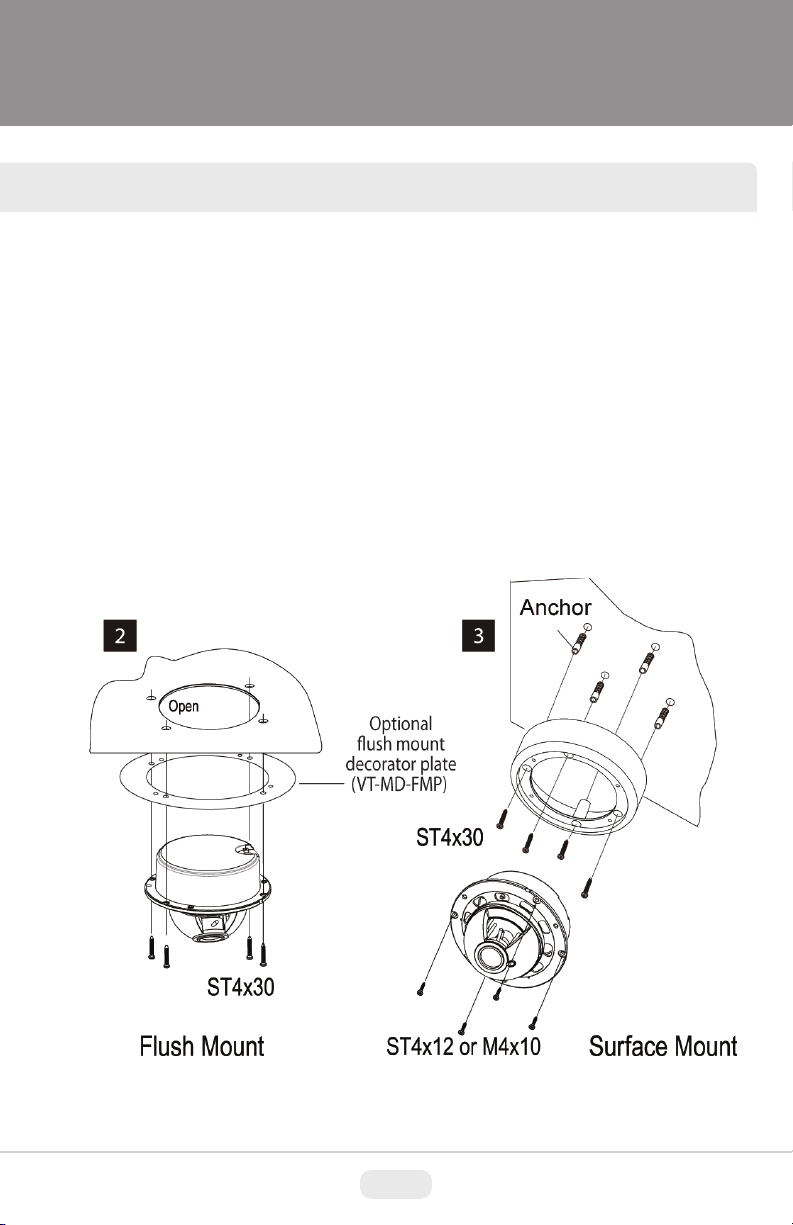
INSTALLATION
1) Dome Cover
1.1 Vandal Proof Domes - Use the provided Torx wrench to unscrew the vandal
proof screws and remove the dome cover.
1.2 Indoor Domes - Turn the dome cover to the left to remove the dome cover.
2) Flush Mount Installation:
Using four St4x30 screws, attach the flush mount base to a sturdy surface.
Optional flush mount decorator plate. Model: VT-MD-FMP
3) Surface Mount Installation:
Drill pilot holes at the mounting location using the provided mounting template.
Using four St4x30 screws, mount the surface mount housing to a sturdy
surface. Using four ST4x12 (Indoor) screws or M4x10 (Vandal-proof) screws,
attach the flush mount base to the surface mount housing.
5
Page 7
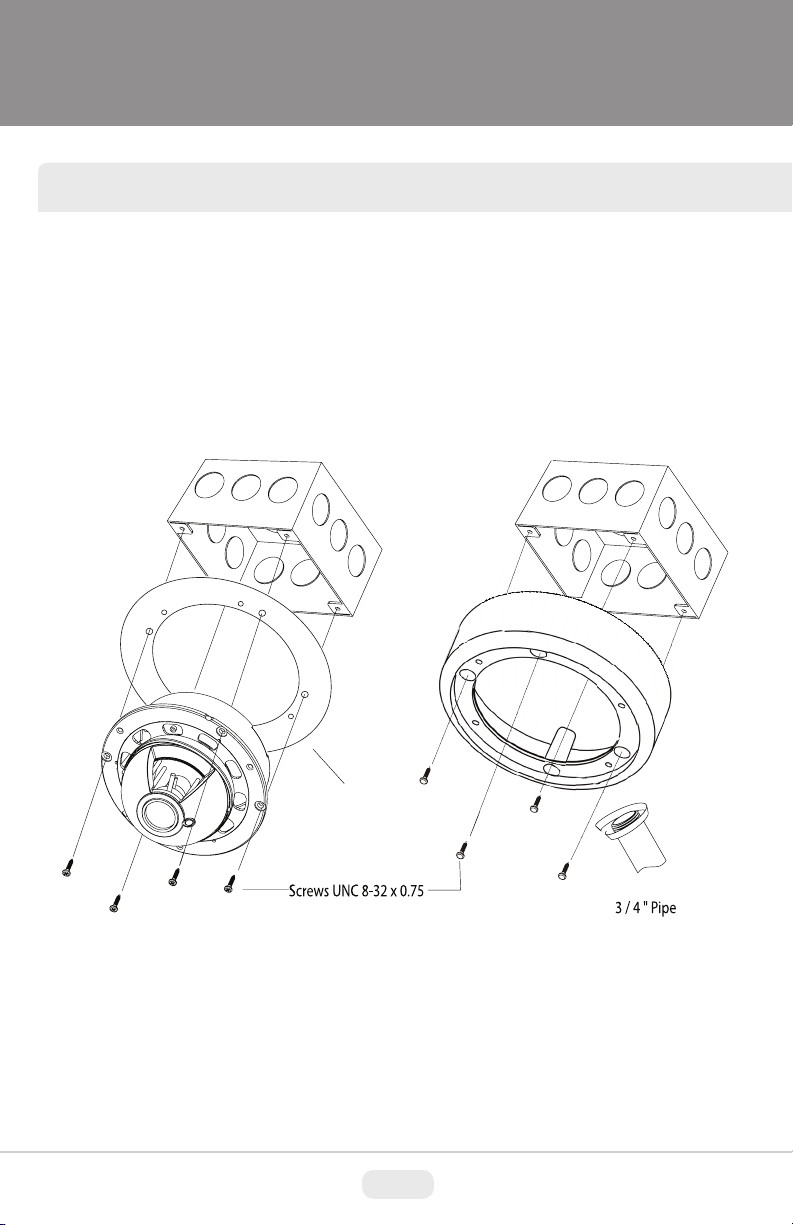
JUNCTION BOX INSTALLATION
Mighty Domes can easily be flush or surface mounted to an electrical junction
box (4S J-Box) using the pre-drilled mounting holes on either the surface mount
housing or the the flush mount base.
Optional
ush mount
decorator plate
(VT-MD-FMP)
6
Page 8
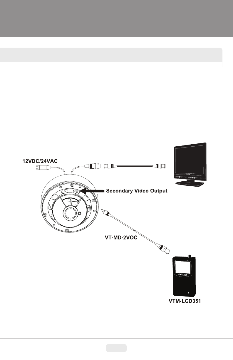
CONNECTIONS
• Power connection: 12VDC or 24VAC dual input.
• All Mighty Dome cameras come standard with a secondary video output. The
secondary video cable (VT-MD-2VOC) is included in the box.
VTM-LCD
7
Page 9
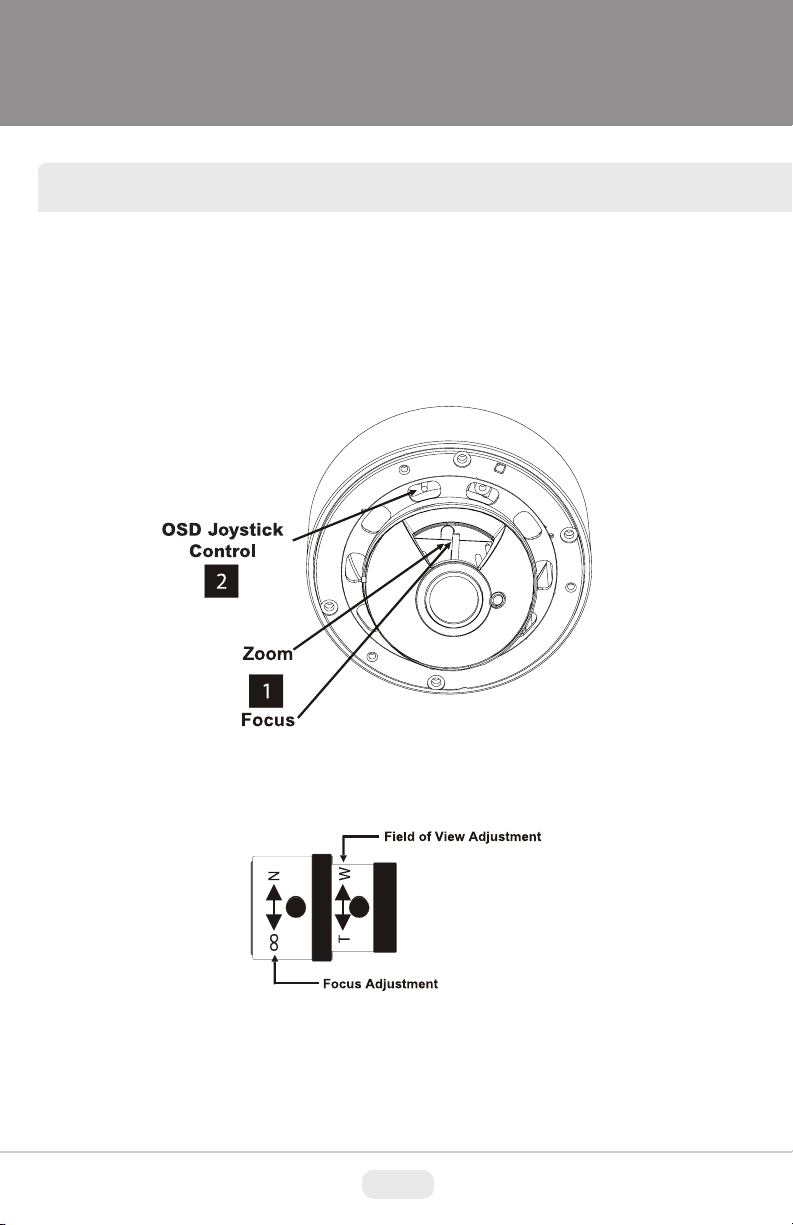
LENS ADJUSTMENT
1) Loosen Zoom & Focus screws and make necessary adjustments as shown.
Field of view: Telephoto(T) to Wide(W)
Focus: Near(N) to infinity( )
2) OSD Joystick Control
8
Page 10
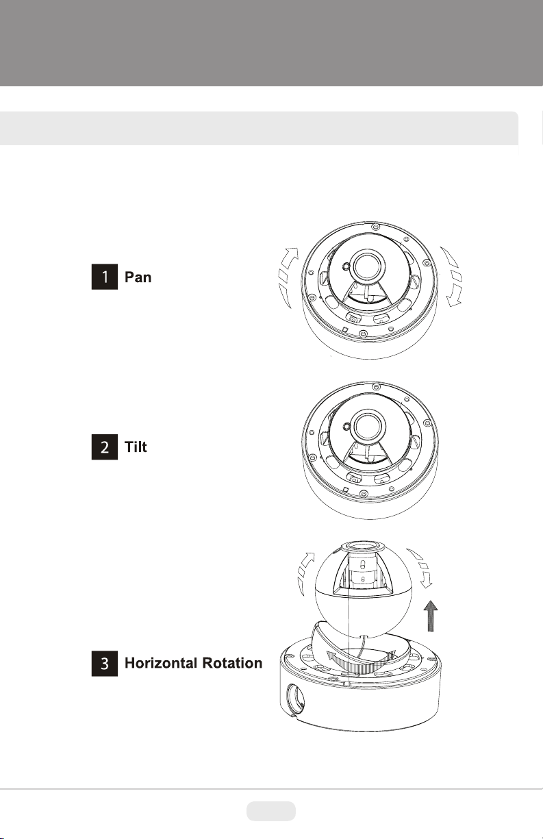
3-AXIS GIMBAL ADJUSTMENT
The Gimbal mechanism yields maximum rotation and placement as shown below.
9
Remove
Page 11
MIGHTY DOME FEATURES
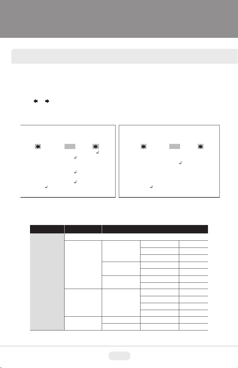
OSD menu Startup
Press the ‘OSD menu SET key’ down to access the setup menu mode.
• / : Selects previous page or next page.
• EXIT : Enters ‘EXIT’ menu.
• RETURN : Returns to the previous menu.
SETUP MENU
1 / 2
SCENE SELECT
PICT ADJUST
EZOOM
DIS
PRIVACY MASK
MOTION DET
SYS SETTING
EXIT
FULL AUTO
OFF
OFF
OFF
OSD menu Table
SETUP MENU
SCENE SELECT
ADVANCED MENU
FULL AUTO/ INDOOR/ OUTDOOR/ BACKLIGHT/ ITS/ CUSTOM
SHUTTER/AGC
WHITE BAL
HLC / BLC
AUTO
MANUAL
FIX
ATW
OFF
HLC
SETUP MENU
LANGUAGE
VERSION
MAINTENANCE
EXIT
CONFIGURATION
AE LEVEL
AGC MAX
SENS UP
SHUTTER
AGC MAX
SHUTTER
AGC MAX
SPEED
DELAY CNT
ATW FRAME
ENVIRONMENT
CLIP LEVEL
2 / 2
ENGLISH
1.01
100
42DB
OFF
1/50(1/60)
42DB
1/50(1/60)
42DB
127
30
200
INDOOR
10
10
Page 12
OSD MENU FEATURES/SETUP
SCENE SELECT
PICT ADJUST
EZOOM
DIS
PRIVACY MASK
WDR / ATR-EX
DNR
DAY/NIGHT
IR OPTIMIZER
LENS SHD COMP
DEFOG
FLK LESS
ANTI CR
BRIGHTNESS
CONTRAST
SHARPNESS
HUE
COLOR GAIN
OFF
ON
OFF / ON
AREA SEL
DISPLAY
POSITION
COLOR
WDR for V-Series, ATR-EX for A-Series
LEVEL
AUTO
ON
OFF (default)
OFF
ON
OFF
ON
OFF
AUTO
ON
AUTO / OFF / ON
120
33
8
64
128
MAG
PAN
TILT
1/15
OFF
3
BURST
CNTL SIGNAL
DELAY CNT
DAY->NIGHT
NIGHT->DAY
MODE
IR AREA
LEVEL
IR LED
COLOR NIGHT
PATTERN
POSH
POSV
LEVEL
MODE
MODE
0
512
256
OFF
EXT1
3
80
120
AUTO
---
3
DAY/NIGHT
ON/OFF
SET1/2/3
480
290
MID
GAIN CNTL
GAIN CNTL
11
Page 13

OSD MENU FEATURES/SETUP
PRIVACY MASK
MOTION DET
SYS SETTING
LANGUAGE
VERSION
MAINTENANCE
EXIT
TRANSP
MOSAIC
OFF
ON
LENS
FLIP
LCD / CRT
CAMERA ID
English/ Spanish/ Russian/ Portuguese/ German/ French/ Chinese/ Japanese
1.01
W.PIX MASK
CAMERA RESET
SAVE / NOT SAVE / CANCEL / BACK
DETECT SENSE
INTERVAL
BLOCK DISP
MASK AREA
MONITOR AREA
AUTO
OFF / V / H / HV
CRT
OFF / ON
MANUAL COMP
AUTO COMP
DATA CLEAR
111
0
OFF
AREA SEL
AREA MODE
TOP
BOTTOM
LEFT
RIGHT
TYPE
MODE
ADJUST
SPEED
REGISTRATION
REG. POINT
CURSOR COLOR
BLINK
REG. NUMBER
LEVEL1 / LEVEL2 / AUTO
YES / NO
1/4
OFF
DC
AUTO
30
12
Page 14

OSD MENU FEATURES/SETUP
OSD menu Setup
Press the OSD menu SET key down to access the setup menu mode.
SETUP MENU
SCENE SELECT
PICT ADJUST
EZOOM
DIS
PRIVACY MASK
MOTION DET
SYS SETTING
EXIT
1 / 2
FULL AUTO
OFF
OFF
OFF
ADVANCED MENU
1 / 2
SHUTTER/AGC
WHITE BAL
HLC/BLC
WDR/ATR-EX
DNR
DAY/NIGHT
IR OPTIMIZER
RETURN
AUTO
ATW
OFF
WDR
NIGHT
ON
1. SCENE SELECT
These options have been pre-configured at the factory for optimal performance.
You can choose one of FULL AUTO, INDOOR, OUTDOOR, BACKLIGHT, ITS and
CUSTOM according to the environments.
Each SCENE preset offers how to set SHUTTER +AGC, WHITE BAL, HLC/BLC,
WDR/ATR-EX, DNR, DAY/NIGHT, IR OPTIMIZER, LENS SHD COMP, DEFOG,
FLK LESS, and ANTI CR functions to get the best image for the SCENE SELECT.
> FULL AUTO: Optimized for the general scene.
> INDOOR: Optimized for indoor environment.
> OUTDOOR: Optimized for outdoor environment.
> BACKLIGHT: Optimized for backlight condition such as near the window in daylight.
> ITS: Optimized for the environment on traffic roads.
> CUSTOM: Setting for user customized environment.
If the selected preset does not seem to be the best choice, further adjustments
are available in each preset.
1-1. SHUTTER/AGC
Sets the SHUTTER/AGC level to AUTO, MANUAL or FIX.
1-1-1. AUTO:
Video level is automatically controlled to follow the settings of AE LEVEL, AGC
MAX, SENS UP. In this mode, ‘DC Auto Iris Lens’ and ‘Fixed Lens’ are available.
1-1-2. MANUAL:
Video level is manually controlled by the settings of SHUTTER, AGC MAX.
In this mode, ‘DC Auto Iris Lens’ is only available.
13
Page 15

OSD MENU FEATURES/SETUP
1-1-3. FIX:
Video level is fixed in any conditions by the setting of SHUTTER, AGC MAX.
1-2. WHITE BAL
Ability to set the WHITE BALANCE mode.
1-2-1. ATW (Auto Trace White Balance):
Automatically tracks the changes of color temperature and continuously adjusts
the white balance. The white balance range is 1,800 °K~10,500°K.
Note: If you set to ‘CUSTOM’ mode in ‘SCENE SELECT’ menu, the ‘WHITE BAL’
sub-menu will appear. ‘ATW/ PUSH/ USER1/ U SER2/ MA NUAL/
PUSH LOCK’ functions that you can select one.
Other modes in ‘SCENE SELECT’ menu, the ‘WHITE BAL’ sub-menu is only ‘
ATW’ function.
ATW
SPEED
DELAY CNT
ATW FRAME
ENVIRONMENT
RETURN
INDOOR
200
020
200
• SPEED (default: 200):
Sets the AWB(Automatic White Balance) compensating speed. Lower value makes
AWB faster. * Too fast AWB may cause color oscillation.
• DELAY CNT (default: 20):
Adjusts the AWB compensation delay to next update of AWB.
The smaller value will update AWB more frequently (faster).
• ATW FRAME (default: 200):
Determines the ATW range with respect to the fundamental range. Higher value
extends the ATW range at lower and higher color temperature.
• ENVIRONMENT (default: INDOOR):
Selects INDOOR, SUNNY, SHADE or AUTO
14
Page 16

OSD MENU FEATURES/SETUP
> INDOOR : Optimized for Indoor installation and more easily compensates ATW
for low color temperature such as incandescent lights.
> SUNNY : Optimized for outdoor sunlight applications and more easily compensates
ATW for high color temperature such as sunlight.
> SHADE : Optimized for shade area compensation.
> AUTO : Optimized for general scene.
1-3. HLC/BLC
HLC (Highlight Cut out) :
This function is used to black out highlighted (bright) areas, in order to enable a clear
visual image of objects, such as the license plates of an oncoming vehicle or other
objects that may be obstructed by headlamps.
HLC OFF HLC ON
BLC OFF BLC ON
BLC (Backlight Compensation) :
This function is used to brighten an image in the foreground with a highly bright area
behind it such as sunlight, limiting the affect of silhouette.
1-3-1. OFF:
Disables HLC and BLC functions.
15
Page 17

OSD MENU FEATURES/SETUP
1-3-2. HLC:
HLC clips out the highlight (bright) area and masks it as black color.
Video will be clipped out and masked for the area which exceeds CLIP LEVEL.
• CLIP LEVEL (default: 10):
Defines the threshold level for HLC. Lower value is more sensitive.
1-3-3. BLC:
Sets BLC function enable or disable
Note: BLC is available only in ‘CUSTOM’ scene preset.
1-4. WDR/ATR-EX
1-4-1. WDR(Wide Dynamic Range): V-Series Only
This function extends the gain range of the screen that is useful if the camera takes a
simultaneous picture of both indoor and outdoor. It improves contrast of the picture in
outdoor scenery as well as indoor. Video image is processed from two images by dual
shutter (long and short shutter) in a field to provide the best dynamic range. Highlight
area is compensated by the short shutter and dark area is compensated by the long
shutter. Final video may have less contrast compared to the conventional camera which
does not have WDR function.
• CONTRAST (default: MID): It can be selected only in ‘CUSTOM’ scene preset.
• CLEAR FACE (default: MID): Selects one of ‘LOW/MID/HIGH’
Note: WDR is fixed except in ‘CUSTOM’ scene preset.
Select one of ‘WDR/ATR-EX/OFF’ in ‘CUSTOM’ scene preset.
Sets BLC function enable or disable.
1-4-2. ATR-EX (Adaptive Tone Reproduction-EX):
Sets enabling/disabling ATR compensation for better dynamic range (D-WDR) of
the image.
ATR feature improves the dynamic range and the visibility of the image by providing
the optimal gradation compensation of the image in one field. This is achieved by
two ways of image processing, luminance compression and contrast enhancement,
so that the tone can be enhanced at highlight (bright) and dark area.
1-5. DNR
DNR(Digital Noise Reduction) function improves picture quality by filtering out signal
noise which is generated under low light conditions. It is 3DNR (3-dimensional noise
reduction) which reduces the noise by multi frame comparison. Noise Reduction is
effective at low light. Setting a higher level of noise reduction may result in the loss of
sharpness and the tail effect of a comet may occur.
16
Page 18

OSD MENU FEATURES/SETUP
1-6. DAY/NIGHT
This function is used to control the setting during day-time and night-time operation.
1-6-1. AUTO
AUTO mode in DAY/NIGHT is used only for a camera which does not have a light
sensor. Camera switches DAY from/to NIGHT automatically according to the
amount of light through the lens.
D/N AUTO SETUP
BURST
CNTL SIGNAL
DELAY CNT
DAY->NIGHT
NIGHT->DAY
RETURN
• BURST (default: OFF)
BURST determines whether a color burst signal keeps outputting or eliminated
when camera switches to B/W.
If set to ON, B/W video signal contains color burst signal and is compatible with
color equipment but shows the same resolution as color video.
If set to OFF the color burst signal is removed from B/W video and shows better
resolution but a compatibility problem may occur with the color equipment.
OFF
EXT1
003
080
120
• CNTL SIGNAL (default: EXT1):
DAY/NIGHT is switched by amount of light through the lens.
Select one of ‘INT/EXT1/EXT2’
• DELAY CNT (default: 3)
DELAY CNT is time in second while camera maintains its status before Day↔
Night switches. DELAY can avoid the unwanted/frivolous switching by a short
term light such as light from a passing car.
• DAY -> NIGHT (default: 80)
DAY→NIGHT is a threshold level which determines to switch from DAY to NIGHT.
Lower(Higher) value makes the camera switch from Day to Night at lower(higher)
illumination. If it stays in Day(Color) mode at night time, inc rease DAY→NIGHT
threshold value until it just switches to Night.
* Examine and verify Day/Night operation according to IMPORTANT ACTIVITY
17
Page 19

OSD MENU FEATURES/SETUP
• NIGHT -> DAY (default: 120)
NIGHT→DAY is a threshold level which determines to switch from NIGHT to DAY.
Lower(Higher) value makes the camera switch from Night to Day at lower
(higher) illumination. If it stays in Night(B/W) mode in day time, decrease NIGHT->
DAY threshold value until it just switches to Day
* Examine and verify Day/Night operation according to IMPORTANT ACTIVITY
1-6-2. DAY :
1-6-3. NIGHT :
• BURST (default: OFF) :
Block the lens for a few seconds for NIGHT mode and release and let it return to
DAY mode. If camera stays at NIGHT mode more than 10sec, decrease NIGHT->
DAY THRESHOLD a little and repeat the fore-mentioned steps. If the scene
is too dim or lens iris was adjusted too low(near close), it may not return to DAY.
The camera is always in Color mode.
The camera is always in B/W mode.
Sets the BURST option ON/OFF to output burst signal in B/W mode.
IMPORTANT ACTIVITY
DAY->NIGHT and NIGHT->DAY operations must be examined and verified at
the final installation.
CAUTION
• Verify ‘DAY/NIGHT’ after completing all settings of lens for zoom and focus.
• If the gap between DAY->NIGHT and NIGHT->DAY is too small, camera may repeat
switching DAY from/to NIGHT. If NIGHT->DAY is decreased from the Factory default,
the same amount is recommended for DAY->NIGHT to avoid repeating
DAY<->NIGHT unintentionally.
18
Page 20

OSD MENU FEATURES/SETUP
1-7. IR OPTIMIZER
This function is effective for built-in LED models in NIGHT mode only.
If subjects which can cause overexposure are located near the monitored area, you
can adjust IR OPTIMIZER level or area.
IR OPTIMIZER SETUP
MODE
IR AREA
LEVEL
IR LED
COLOR NIGHT
IR SHADE COMP
RETURN
AUTO
---
002
DAY/NIGHT
OFF
OFF
1-7-1. MODE : AUTO
Reducing the over-saturation is automatically adjusted along with the location of
the subject.
1-7-2. IR AREA :
Sets the IR OPTIMIZER AREA this function works in
‘CUSTOM preset only.
1-7-3. LEVEL (default: 002):
This function is used to adjust the overall when IR OPTIMIZER is working.
If the LEVEL is too high, over-saturation could occur.
1-7-4. IR LED: Sets the IR LED ON/OFF controlling
• DAY/NIGHT : Follows the setting of DAY/NIGHT function.
• OFF : Turns IR LED off.
• FIX : Fixes the brightness of IR LED in any condition.
1-7-5. COLOR NIGHT (default: OFF): Displays night video in color.
1-7-6. IR SHADE COMP (default: OFF):
This function is used to compensate
for IR shade of the side areas on screen
when IR LED is ON. You can adjust
the shading PATTERN, POSITION
and LEVEL.
If the LEVEL is high, the screen noise
could be increased at the side areas.
IR LED AUTO
LEVEL MIN
LEVEL MAX
RETURN
IR SHADE COMP SETUP
PATTERN
POSH
POSV
LEVEL
RETURN
006
255
SET1
006
255
MID
19
Page 21

OSD MENU FEATURES/SETUP
1-8. LENS SHD COMP (default: OFF)
This function is used to caculate the compensation data for lens shading.
Convex shape of the lens causes the light to enter the camera unevenly and typically
makes the center of the screen brighter than the rest. It is used to compensate for this
undesirable effect and make the screen more even.
Set to ‘ON’, you can adjust the shading PATTERN and POSITION.
LENS SHD COMP
PATTERN
POSH
POSV
RETURN
SET1
480
290
1-9. DEFOG (default: ON)
This function is used to carry out defog function. Sets LEVEL to eliminate amount of
fog on screen.
If the DEFOG is set to ON, the WDR/BLC function will be deactivated.
1-10. FLK LESS (default: AUTO)
This function is used to remove the flickering on screen due to differences in light and
electric frequencies.
1-11. ANTI-CR (default: AUTO)
This mode can minimize problems related to color rolling caused by differences
between the flicker of fluorescent lights and the frequency of the camera.
2. PICT ADJUST
PICT ADJUST
BRIGHTNESS
CONTRAST
SHARPNESS
HUE
COLOR GAIN
120
033
008
064
128
RETURN
20
Page 22

OSD MENU FEATURES/SETUP
2-1. BRIGHTNESS (default: 120):
Increases or decreases the brightness of the picture.
This is different from that of DC iris lens and simply increases or decreases the digital
gain of video. Do not increase this too much, the dynamic range for the highlight area
will decrease.
2-2. CONTRAST (default: 033):
Adjusts the strength of the image contrast. If set to too high, the dark area may loss
detail and the high luminance area may saturate.
2-3. SHARPNESS (default: 008):
Increases or decreases the sharpness of the picture.
Too much sharpness can make image harsh and show more noise as well as line
flicker at the edge of objects in the picture.
2-4. HUE (default: 064): Adjusts hue for NTSC version only.
2-5. COLOR GAIN (default: 128): Increases or decreases the color saturation.
3. EZOOM
Sets the maximum digital zoom magnification. E.ZOOM function enlarges the pixel
itself, which can cause deterioration of the picture quality.
3-1. MAG (default: 000):
MAG is the magnification ratio of the electronic zoom. Sets from x000 to x255.
3-2. PAN (default: 512):
When MAG is greater than 0, the electronic pan is available.
000 is the left most pan and 1023 is the right most pan.
3-3. TILT (default: 256):
When MAG is greater than 0, the electronic tilt is available.
000 is the upper most tilt and 511 is the lower most tilt.
4. DIS (Digital Image Stabilization)
This function is used to reduce and stabilizest a shaky image from a camera installed
in an area with vibration. FOV(Field of view) will be reduced if set to ON.
21
Page 23

OSD MENU FEATURES/SETUP
5. PRIVACY MASK
Sets ON/OFF for enabling/disabling PRIVACY.
Up to 15 privacy areas are available and each area is programmable in size and
location. The number of privacy areas is limited to four when MOTION DET >
MONITOR AREA is ON.
The privacy areas are masked with the color selected by PRIVACY MASK>COLOR.
PRIVACY MASK SETUP
AREA SEL
DISPLAY
POSITION
COLOR
TRAMSP
MOSAIC
RETURN
5-1. AREA SEL (default: 1/15)
1/15
ON
RED
1.00
-----
: Selects one of AREA1~AREA15 to be adjusted.
5-2. DISPLAY (default: OFF)
Displays OFF/ON for the mask area which you selected ‘AREA SEL’
5-3. POSITION : Adjusts the mask area X,Y-Axis position which you selected ‘AREA SEL’
• TOP/BOTTOM: ◄button moves up and ►button moves down the top (bottom)
border of the selected window at AREA SEL.
• LEFT/RIGHT: ◄button moves left and ►button moves right the left (right) border
of the selected window at AREA SEL.
5-4. COLOR
: Selects one of 8 colors (Red, Green, Blue, Yellow, Cyan, Magenta, White,
Black) for the selected mask window at AREA SEL.
5-5. TRANSP : Transparency rate for the mask can be adjusted.
0.00 - Mask is fully transparent and not visible.
0.50 - Mask is 50% transparent.
0.75 - Mask is 25% transparent.
1.00 - Mask is not transparent.
5-6. MOSAIC
Enables or disables the mosaic effect for the selected mask window at AREA SEL
22
Page 24

OSD MENU FEATURES/SETUP
6. MOTION DET
Up to 4 motion detection areas are available and each area is programmable in size
and location. The motion is displayed by means of blocks when MOTION DET and
MOTION DET>BLOCK DISP are ON.
MOTION DETECTION
DETECT SENSE
INTERVAL
BLOCK DISP
MASK AREA
MONITOR AREA
RETURN
6-1. DETECT SENSE
OFF
(default: 111)
111
000
Adjusts the sensitivity for detecting motion. Higher value is more sensitive.
6-2. INTERVAL (default: 0)
Sets the interval time from the starting of motion operation until being ready for the next
motion operation.
6-3. BLOCK DISP (default: OFF)
Enables or disables displaying blocks for the area which the motion is detected
6-4. MASK AREA
Sets MASK AREA for disabling MOTION DETECTION.
Selects number of area cells to set the area you need.
1 2 3 4 5 6 7 8 9 10 11 12
13 14 15 16 17 18 19 20 21 22 23 24
25 26 27 28 29 30 31 32 33 34 35 36
37 38 39 40 41 42 43 44 45 46 47 48
49 50 51 52 53 54 55 56 57 58 59 60
61 62 63 64 65 66 67 68 69 70 71 72
73 74 75 76 77 78 79 80 81 82 83 84
85 86 87 88 89 90 91 92 93 94 95 96
RETURN
23
Page 25

OSD MENU FEATURES/SETUP
6-5. MONITOR AREA
Sets the MOTION DETECTION area on screen.
MONITOR AREA
AREA SEL
AREA MODE
TOP
BOTTOM
LEFT
RIGHT
RETURN
6-5-1. AREA SEL
1/4
ON
03
04
04
08
(default: 1/4) : Selects one of AREA1~AREA4 to be adjusted.
Each area is displayed with the color. AREA1-Red, AREA2-Green, AREA3 Blue, AREA4-Yellow
6-5-2. AREA MODE (default: OFF):
Setting ON activates the AREA SEL which you selected.
6-5-3. TOP/ BOOTTOM / LEFT / RIGHT
Sets the AREA SEL box sizes and positions with four direction points.
• TOP/BOTTOM: ◄button moves up and ►button moves down the top (bottom)
border of the selected window at AREA SEL.
• LEFT/RIGHT: ◄button moves left and ►button moves right the left (right) border
of the selected window at AREA SEL.
7. SYS SETTING
Sets the system related functions.
SYSTEM SETTING
LENS
FLIP
LCD/CRT
COMMUNICATION
CAMERA ID
AUTO
OFF
CRT
OFF
RETURN
24
Page 26

OSD MENU FEATURES/SETUP
7-1. LENS
Selects the lens type, AUTO or MANUAL. AUTO supports DC auto-iris lens only.
7-1-1. AUTO
• TYPE (default: DC): This camera does NOT support video type auto iris lens.
MUST BE SET TO DC ONLY.
• MODE (default: AUTO):
Lens iris is automatically controlled according to the scene light level.
• ADJUST : Adjusts lens open control regardless of the light level.
• SPEED (default: 30):
Adjusts the iris control speed. The lower value is the faster speed.
If the speed is too slow or fast, the iris control may be unstable.
7-2. FLIP :
This function is used to inverse the pictures coming from the camera.
• V : Flips the video signals vertically.
• H : Flips the video signals horizontally.
• HV : Flips the video signals horizontally and vertically.
7-3. LCD/CRT (default: CRT):
Select the correct type of viewing monitor will ensure the most optimal picture.
7-4. COMMUNICATION
Sets the communication related function.
PROTOCOL(PELCO-D), BAUDRATE(9600), DATABIT(8), PARITY(OFF), STOPBIT(1)
are fixed. Can set only ADDRESS number.
COMMUNICATION
PROTOCOL
ADDRESS
BAUDRATE
DATABIT
PARITY
STOPBIT
RETURN
PELCO-D
001
9600
8BIT
OFF
1BIT
25
Page 27

OSD MENU FEATURES/SETUP
7-4. CAMERA ID
Set ON/OFF for enabling/disabling of ID display. Factory default ID is Software
version of camera. User programmed camera ID will be lost and restored with
factory default ID by CAMERA RESET.
Up to 40 characters can be input for camera ID.
CAMERA ID SETUP
VER-DN1.0
ABCDEFGH IJKLMNOPQRSTUV
WXYZ0123456789-!”#$% &’(
)_`,¥:;<=>?@ \^*↑↓←→/
CHR1 CHR2
CLR
RETURN
● Use four direction buttons (▲/▼/◄/►) to move the block cursor in character table
and press the set button (
To move the character input position on CAMERA ID input line, move the cursor to
← or → on COMMAND LINE and press the set button on ← or →.
● CLR : To clear CAMERA ID input line, move the cursor to CLR on COMMAND LINE
and press a set button (
● POS : To set the location of CAM TITLE to be displayed on the monitor, move the
cursor to POS and press the set button (
CAMERA ID will be displayed on the monitor.
Move CAMERA ID to desired position by using four direction buttons (▲/▼/◄
/ ►) then press the set button (
8. LANGUAGE
8 languages, ENGLISH, SPANISH, RUSSIAN, PORTUGUESE, GERMAN,
FRENCH, CHINESE and JAPANESE are available.
9. VERSION
The camera firmware version is displayed.
◙).
POS
◙) to input the selected character.
◙) and then the OSD menu disappears and
◙) to fix. The OSD Menu will appear again.
CAMERA ID input line
COMMAND line
26
Page 28

OSD MENU FEATURES/SETUP
10. MAINTENANCE
Set the OSD menu user environments and Camera reset.
MAINTENANCE
W.PIX MASK
CAMERA RESET
RETURN
MANUAL
10-1-1. MANUAL COMP
: Setting for white pixel(defective pixels) compensation manually.
• REGISTRATION : Detects each white pixel using the cursor.
• REG. POINT : Displays white pixels in color which you detected.
• CURSOR COLOR : Selects cursor color one of green, red, or blue.
• BLINK : Sets the cursor blink or not.
• REG. NUMBER : Displays quantity of detected white pixels.
10-1. W.PIX MASK
This function is used to compensate white pixels(defective pixels).
MANUAL COMP
REGISTRATION
REG.POINT
CURSOR COLOR
BLINK
REG. NUMBER
RETURN
OFF
WHITE
OFF
3 / 64
AUTO COMP
LEVEL1
LEVEL2
AUTO
RETURN
003
255
10-1-2. AUTO COMP
: Setting for white pixels(defective pixels) compensation automatically.
• LEVEL1 : Sets the threshold of the detection for white pixels.
• LEVEL2 : Sets the threshold of the detection for very large white pixels.
• AUTO : Starts the automatic detection of white pixels.
27
Page 29

OSD MENU FEATURES/SETUP
10-2. CAMERA RESET
This function is used to reset to the factory defaults of the camera settings.
11. EXIT
Exits SETUP MENU and returns to the normal display.
11-1. SAVE : Save all the setting before exiting the setup menu.
11-2. NOT SAVE : Exit the setup menu without saving.
11-3. CANCEL : Cancel the exit mode.
11-4. BACK : Go back to the previous menu mode.
HEATER / BLOWER OPTION (Vandal Versions)
Detailed Specifications VT-MD-HB24
Power Supply
Power Consumption
Heater
Blower
Extreme Weather Heater - Optional
10W (Heater) / .7W (Blower)
Continuous 24 Hour Operation
24 VAC
On: at 41ºF / Off at 59ºF
Operation down to -60ºF
28
Page 30

INDOOR WDR SPECIFICATIONS
Detailed Specifications VTD-MS2810WDR VTD-MS922WDR
Image Device
Resolution
Effective Pixels
Minimum Illumination
Lens Options
Day/Night
WDR
Noise Reduction
Motion Detection
Privacy Mask
White Balance
FLIP
Synchronization
S/N Ratio
Electronic Iris
Advanced OSD Functions
OSD Language
Digital Image Stabilazation
DSS
Digital Zoom
Power Source
Power Consumption (12VDC)
Power Consumption (24VAC)
Operating Conditions
Dimensions (H x Dia.)
Weight
1/3” 960H High Density Double Scan Sony CCD w/Effio-V
750TV Lines
976(H) x 494(V)
0.0001 Lux (F1.2@40 IRE, DSS x4)
2.8-10mm 9-22mm
True Day/Night by ICR
YES
XD-DNR (2D+3D DNR)
4 Programmable Zones
Polygon Masking with 15 Programmable Zones
ATW / PUSH / USER1 / USER2 / MANUAL / PUSH LOCK
H-Flip, V-Flip, H/V Flip
Internal
More than 52dB with AGC OFF at 50IRE
1/60 ~ 1/100,000sec
Defog, BLC/HLC, Privacy Masking, Motion Detection, Flip, LSC
English, Spanish, Portuguese, German, French, Russian, Chinese
YES
YES
Up to X12 Digital Zoom
UL Certified: 12VDC / 24VAC
2.64 W / 220 mA
2.64 W / 110 mA
-4°~122°F (-20°-50°C)
4.45” x 5.71” (113mm x 145mm)
1lb / .46Kg
29
Page 31

VANDAL WDR SPECIFICATIONS
Detailed Specifications VTD-MVS2810WDR VTD-MVS922WDR
Image Device
Resolution
Effective Pixels
Minimum Illumination
Lens Options
Day/Night
WDR
Noise Reduction
Motion Detection
Privacy Mask
White Balance
FLIP
Synchronization
S/N Ratio
Electronic Iris
Advanced OSD Functions
OSD Language
Digital Image Stabilazation
DSS
Digital Zoom
Water Resistance
Power Source
Power Consumption (12VDC)
Power Consumption (24VAC)
Operating Conditions
Dimensions (H x Dia.)
Weight
1/3” 960H High Density Double Scan Sony CCD w/Effio-V
750TV Lines
976(H) x 494(V)
0.0001 Lux (F1.2@40 IRE, DSS x4)
2.8-10mm 9-22mm
True Day/Night by ICR
YES
XD-DNR (2D+3D DNR)
4 Programmable Zones
Polygon Masking with 15 Programmable Zones
ATW / PUSH / USER1 / USER2 / MANUAL / PUSH LOCK
H-Flip, V-Flip, H/V Flip
Internal
More than 52dB with AGC OFF at 50IRE
1/60 ~ 1/100,000sec
Defog, BLC/HLC, Privacy Masking, Motion Detection, Flip, LSC
English, Spanish, Portuguese, German, French, Russian, Chinese
YES
YES
Up to X12 Digital Zoom
IP-68
UL Certified: 12VDC / 24VAC
2.64 W / 220 mA
2.64 W / 110 mA
-4°~122°F (-20°-50°C)
4.45” x 6.73” (110mm x 170mm)
2.3 lb / 1.04Kg
30
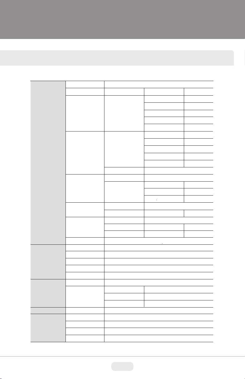
Page 32

INDOOR DAY/NIGHT SPECIFICATIONS
Detailed Specifications VTD-MS2810DN VTD-MS922DN VTD-MS1850DN
Image Device
Resolution
Effective Pixels
Minimum Illumination
Lens Options
Day/Night
WDR
Noise Reduction
Motion Detection
Privacy Mask
White Balance
FLIP
Synchronization
S/N Ratio
Electronic Iris
Advanced OSD Functions
OSD Language
Digital Image Stabilazation
DSS
Digital Zoom
Power Source
Power Consumption (12VDC)
Power Consumption (24VAC)
Operating Conditions
Dimensions (H x Dia.)
Weight
1/3” 960H High Density Double Scan Sony CCD w/Effio-A
750TV Lines
976(H) x 494(V)
0.0005Lux (Sens-up OFF)
2.8-10mm 18-50mm
Polygon Masking with 15 Programmable Zones
ATW / PUSH / USER1 / USER2 / MANUAL / PUSH LOCK
More than 52dB with AGC OFF at 50IRE
Defog, BLC/HLC, Privacy Masking, Motion Detection, Flip, LSC
English, Spanish, Portuguese, German, French, Russian, Chinese
UL Certifieed: 12VDC / 24VAC
4.45” x 5.71” (113mm x 145mm)
9-22mm
True Day/Night by ICR
D-WDR by ATR-EX2
XD-DNR (2D+3D DNR)
4 Programmable Zones
H-Flip, V-Flip, H/V Flip
Internal
1/60 ~ 1/100,000sec
YES
YES
Up to X12 Digital Zoom
2.64 W / 220 mA
2.64 W / 110 mA
-4°~122°F (-20°-50°C)
1lb / .46Kg
31
Page 33

VANDAL DAY/NIGHT SPECIFICATIONS
Detailed Specifications VTD-MVS2810DN VTD-MVS922DN VTD-MVS1850DN
Image Device
Resolution
Effective Pixels
Minimum Illumination
Lens Options
Day/Night
WDR
Noise Reduction
Motion Detection
Privacy Mask
White Balance
FLIP
Synchronization
S/N Ratio
Electronic Iris
Advanced OSD Functions
OSD Language
Digital Image Stabilazation
DSS
Digital Zoom
Water Resistance
Power Source
Power Consumption (12VDC)
Power Consumption (24VAC)
Operating Conditions
Dimensions (H x Dia.)
Weight
1/3” 960H High Density Double Scan Sony CCD w/Effio-A
750TV Lines
976(H) x 494(V)
0.0005Lux (Sens-up OFF)
2.8-10mm 18-50mm
Polygon Masking with 15 Programmable Zones
ATW / PUSH / USER1 / USER2 / MANUAL / PUSH LOCK
More than 52dB with AGC OFF at 50IRE
Defog, BLC/HLC, Privacy Masking, Motion Detection, Flip, LSC
English, Spanish, Portuguese, German, French, Russian, Chinese
UL Certified: 12VDC / 24VAC
4.45” x 6.73” (110mm x 170mm)
9-22mm
True Day/Night by ICR
D-WDR by ATR-EX2
XD-DNR (2D+3D DNR)
4 Programmable Zones
H-Flip, V-Flip, H/V Flip
Internal
1/60 ~ 1/100,000sec
YES
YES
Up to X12 Digital Zoom
IP-68
2.64 W / 220 mA
2.64 W / 110 mA
-4°~122°F (-20°-50°C)
2.3 lb / 1.04Kg
32
Page 34

IR SPECIFICATIONS
Detailed Specifications VTD-MVS2810/L35 VTD-MVS922/L35 VTD-MVS1850/L35
Image Device
Resolution
Effective Pixels
Minimum Illumination
Lens Options
IR LEDs (Built-In)
Day/Night
WDR
Noise Reduction
Motion Detection
Privacy Mask
White Balance
FLIP
Synchronization
S/N Ratio
Electronic Iris
Advanced OSD Functions
OSD Language
Digital Image Stabilazation
DSS
Digital Zoom
Power Source
Power Consumption (12VDC)
Power Consumption (24VAC)
Operating Conditions
Dimensions (H x Dia.)
Weight
1/3” 960H High Density Double Scan Sony CCD w/Effio-A
750TV Lines
976(H) x 494(V)
0.0005Lux (Sens-up OFF) / 0 Lux w/IR ON
2.8-10mm 18-50mm
35 IR LED’s with up to 120’ Range
Polygon Masking with 15 Programmable Zones
ATW / PUSH / USER1 / USER2 / MANUAL / PUSH LOCK
More than 52dB with AGC OFF at 50IRE
Defog, BLC/HLC, Privacy Masking, Motion Detection, Flip, LSC
English, Spanish, Portuguese, German, French, Russian, Chinese
UL Certified: 12VDC / 24VAC
150mA (IR OFF) / 480mA (IR ON)
170mA (IR OFF) / 430mA (IR ON)
4.45” x 6.73” (110mm x 170mm)
9-22mm
True Day/Night by ICR
D-WDR by ATR-EX2
XD-DNR (2D+3D DNR)
4 Programmable Zones
H-Flip, V-Flip, H/V Flip
Internal
1/60 ~ 1/100,000sec
YES
YES
Up to X12 Digital Zoom
-4°~122°F (-20°-50°C)
1lb / .46Kg
33
Page 35

DIMENSIONS
Indoor Vandal
31
34
Page 36

OTHER PRODUCTS FROM VITEK
VTC-C960DS / VTC-C960WS
750 TVL 960H True Day/Night CCD Cameras w/Effio-A/V
Processing
• VTC-C960DS: 750 TVL 960H True Day/Night CCD Camera w/Effio-A
Processing
• VTC-C960WS: 750 TVL 960H WDR Day/Night CCD Camera w/Effio-V
Processing
• 1/3” High density Sony CCD (960H)
• High Resolution of 750 Horizontal Lines
• Small scale design to fit in 5” dome enclosures such as the Pelco DF5
Housing
• E-WDR by ATR-EX (Adaptive Tone Reproduction) (VTC-C960DS)
• True WDR (Wide Dynamic Range) (VTC-C960WS)
• Sensitivity of 0.0005 Lux
• XD-DNR (2D+3D DNR) Advanced Digital Noise Reduction
• True Day/Night by ICR - Infrared Cut Removal
• Built-in Motion Detection with a 24x16 Grid
• Privacy Mask function with up to 15 programmable mask areas
• 12VDC / 24VAC Dual Voltage Operation
• Lenses Sold Separately
35
Page 37

OTHER PRODUCTS FROM VITEK
SPIRE Elite Series
960H Digital Video Recorders
VT-SRE Series
Spire Series 4, 8, & 16 Channel 960H Digital Video Recorders
• Supports High Resolution 960H Cameras
• 4, 8 or 16 Video Inputs with 1 HDMI, 1 Spot Monitor Output and 1 VGA
output
• H.264 Compression
• Up to 480fps Live Display & 480fps Recording (VT-SRE916) / 240/240
(VT-SRE908) / 120/120 (VT-SRE904)
• Supports both Dynamic and Static IP Addresses
• 4 Audio Inputs / 1 Audio Out
• 4 Alarm Inputs / 2 Relays Out
• Supports Four internal Hard Drives (VT-SRE908/VT-SRE916) / Two
internal Hard Drive (VT-SRE904)
• Supports 4TB Hard Drives
• Remote Viewing over the Internet via Web Browser or LAN
• Applications for iPhone, iPad, iTouch and Android Devices
• “Quick Search” Function for automatic review
• Mac OSX Client & CMS Central Management Software Included
• Automatic sending of Health & Event notifications via email
• Control locally via Front Panel Controls, USB Mouse or with the Included
IR Remote control
• PTZ Control over RS-485
• Rack Mountable (Optional VT-SRE-RK Rack Kit)
36
Page 38

LIMITED LIABILITY WARRANTY
VITEK products carry a three (3) year limited warranty. VITEK warrants
to the purchaser that products manufactured by VITEK are free of any
rightful claim of infringement or the like, and when used in the manner
intended, will be free of defects in materials and workmanship for a
period of three (3) years, or as otherwise stated above, from the date of
purchase by the end user. This warranty is nontransferable and extends
only to the original buyer or end user customer of a VITEK Authorized
Reseller.
The product must have been used only for its intended purpose, and
not been subjected to damage by misuse, willful or accidental damage,
caused by excessive voltage or lightning.
The product must not have been tampered with in any way or the guarantee will be considered null and void.
This guarantee does not affect your statutory rights.
Contact your local VITEK Reseller should servicing become necessary.
VITEK makes no warranty or guarantee whatsoever with respect to
products sold or purchased through unauthorized sales channels. Warranty support is available only if product is purchased through a VITEK
Authorized Reseller.
28492 Constellation Road ValenCia, Ca 91355
WWW.ViteKCCtV.CoM
September 2014
Version 2.0
 Loading...