

Page 1
Mighty Series
WDR Dome
700 TVL Pixim-Powered
WDR Dome Cameras
VITEK
• Pixim D8800C Seawolf Digital Imaging System CMOS
• 700 TVL High Resolution
Cameras
• WDR - Wide Dynamic Range
• 3DNR - Three Dimensional Noise Reduction
• Secondary Video Output (Cable Included)
• OSD (On Screen Display) for Camera Function Setup
• Flush or Surface Mount
• Infinity Ball Mount for Any Viewing Angle
• UTP interface and Heater / Blower Options Available
• UTC Control - Serial Control over Coax
• ¾” Conduit Knockouts
• Indoor and Vandal/Water Resistant IP 686 Rated Models
• Optional Extreme Cold (-60°F) Temperature Kit available
• Available in Ivory or Black
• Dual Voltage 12VDC & 24VAC
Page 2

TABLE OF CONTENTS
BOX CONTENTS
MOUNTING ACCESSORIES
AVAILABLE MODELS/ACCESSORIES
MIGHTY DOME LAYOUT
INSTALLATION
JUNCTION BOX INSTALLATION
OPEN GIMBAL COVER
CONNECTIONS
LENS ADJUSTMENT
INFINITE AXIS GIMBAL ADJUSTMENT
WDR MIGHTY DOME FEATURES
OSD MENU FEATURES/SETUP
1. In the menu
2. Entering Menu
3. MAIN
4. EXPOSURE
5. DAY/NIGHT
6. 3D NR
7. DC LENS or MANUAL LENS
8. PICTURE CONTROL
9. SPECIAL
10. MOTION
11. PRIVACY AREA
12. RS 485 CONTROL
13. D-EFFECT
14. EXIT
DIMENSIONS
HEATER/BLOWER SPECIFICATIONS
INDOOR MIGHTY DOME SPECIFICATIONS
VANDAL MIGHTY DOME SPECIFICATIONS
WARRANTY
1
1
2
3
4
5
6
7
8
9
10
10
11
11
11
12
13
14
14
15
15
16
17
18
18
19
20
21
22
23
26
Page 3
BOX CONTENTS
1) Dome Camera
2) Accessories
VITEK
3) VT-MD-2VOC (Secondary Video Output Cable)
4) Instruction Manual & Mounting Template
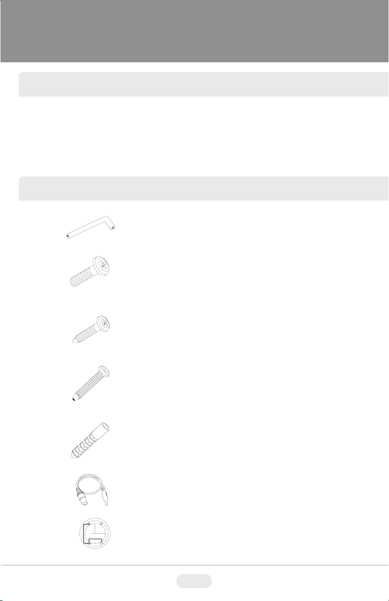
INCLUDED ACCESSORIES
Torx Wrench - (Vandal & IR Versions Only)
Type #: T20
Length: 63mm / Diameter: 4mm
Qty: 1
Phillips head Screws - (Vandal & IR Versions Only)
For attaching the dome cover to the flush housing.
Type #: Phillips head M4x10
Length: 10mm / Diameter: 4mm
Qty: 4
Self Tapping Screws
For attaching the surface mount housing or the the flush mount base
to a solid surface.
Type #: Phillips St4x30
Length: 30mm / Diameter: 4mm
Qty:4
Self Tapping Screws - (Indoor Version Only)
For attaching the dome cover to the flush housing.
Type #: Phillips St4x12
Length: 12mm / Diameter: 4mm
Qty: 4
Dowels
If necessary, use the to help secure the self tapping screws.
Length: 30mm / Diameter: 7mm
Qty: 4
Secondary Video Output Cable for Mighty Domes:
VT-MD-2VOC
For viewing video image during installation.
Qty: 1
Mounting Template
Surface Mount
109.0
70.0
Mounting Template
Qty: 1
1
Page 4

AVAILABLE MODELS / ACCESSORIES
Indoor MIghty doMe ConfIguratIons:
VTD-MP2810WDR: Indoor Wide Dynamic Range Color Dome Camera with
2.8-10mm Varifocal Lens & 700TVL
VTD-MP922WDR: Indoor Wide Dynamic Range Color Dome Camera with
9-22mm Varifocal Lens & 700TVL
VTD-MP1850WDR: Indoor Wide Dynamic Range Color Dome Camera with
18-50mm Varifocal Lens & 700TVL
Vandal resIstant MIghty doMe ConfIguratIons:
VTD-MVP2810WDR: Vandal Resistant Wide Dynamic Range Color Dome
Camera with 2.8-10mm Varifocal Lens & 700TVL
VTD-MVP922WDR: Vandal Resistant Wide Dynamic Range Color Dome
Camera with 9-22mm Varifocal Lens & 700TVL
VTD-MVP1850WDR: Vandal Resistant Color Dome Camera with 18-50mm
Varifocal Lens & 700TVL
optIonal Mounts & aCCessorIes:
1. Heater/Blower Option 24VAC: (Vandal Resistant Models)
2. UTP Option: Unshielded Twisted Pair Transceiver Built-In
3. VT-MD/FMP: Flush Mount Plate for installation in drop ceilings or can be used
as cover plate when using 4S Junction Box
4. VT-MD/PLMT: Mighty Dome Pole Mount Adapter - Requires VT-MD/WMT
Wall Mount
5. VT-MD/CMT: Mighty Dome Ceiling/Pedestal Mount (Can be extended if
necessary)
6. VT-MD/CNMT: Mighty Dome Corner Mount Adapter - Requires
VT-MD/WMT Wall Mount
7. VT-MD/WMT: Mighty Dome Wall Mount (Available In Ivory or Black)
1. 2. 3. 4. 5. 6. 7.
2
Page 5
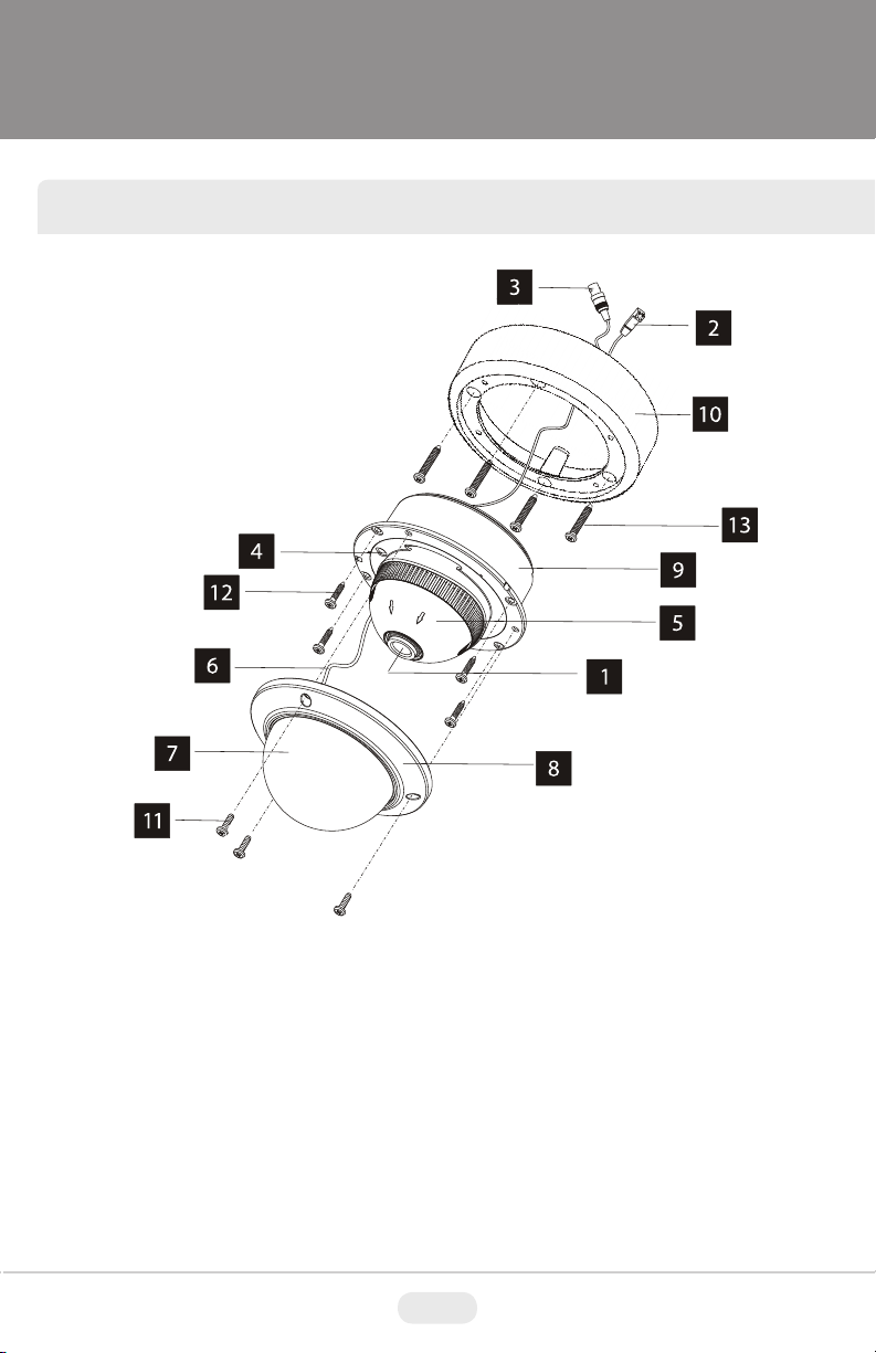
MIGHTY DOME LAYOUT
1) Lens
2) Power Input Connector(12VDC /
24VAC)
3) Video Output Connector - BNC
4) Camera Holder and 2nd Video
output
5) Ball with the Camera Assembly
6) Safety Wire
7) Bubble
8) Dome Cover Ring
9) Flush Mount Base
10) Surface Mount Plate
11) Assembly Screws - Torx M4x9
(Vandalproof)
12) Assembly Screws - Phillips
ST4x12 (Indoor) / Phillips M4x10
(Vandalproof / IR)
13) Mounting Screws - Phillips ST4x30
3
Page 6
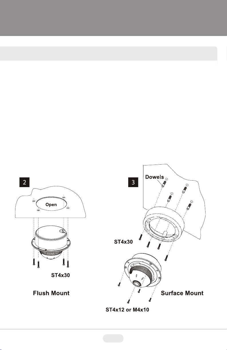
INSTALLATION
1) Dome Cover
1.1 Vandal Proof Domes - Use the provided Torx wrench to unscrew the vandal
proof screws and remove the dome cover.
1.2 Indoor Domes - Turn the dome cover to the left to remove the dome cover.
2) Flush Mount Installation:
Using four St4x30 screws, attach the flush mount base to a sturdy surface.
Optional flush mount decorator plate. Model: VT-MD-FMP
3) Surface Mount Installation:
Drill pilot holes at the mounting location using the provided mounting template.
Using four St4x30 screws, mount the surface mount housing to a sturdy
surface. Using four ST4x12 (Indoor) screws or M4x10 (Vandal-proof) screws,
attach the flush mount base to the surface mount housing.
4
Page 7
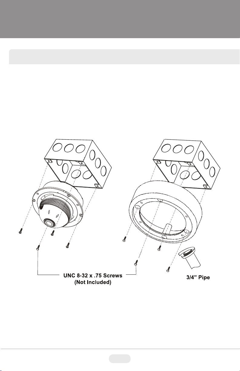
JUNCTION BOX INSTALLATION
Mighty Domes can easily be flush or surface mounted to an electrical junction
box (4S J-Box) using the pre-drilled mounting holes on either the surface mount
housing or the the flush mount base.
5
Page 8
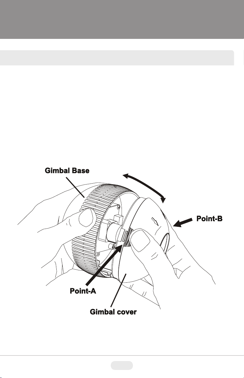
OPEN GIMBAL COVER
To adjust the zoom and the focus, the gimbal needs to be removed temporarily
from its base.
1) Remove the ball gimbal from its socket, and hold the base firmly with one hand.
2) Gently squeeze Point A and B and pull away from the base until the gimbal is
removed from the base.
3) Replace the Gimbal cover by aligning the cover to the base and pressing down
until it snaps back onto the base.
6
Page 9
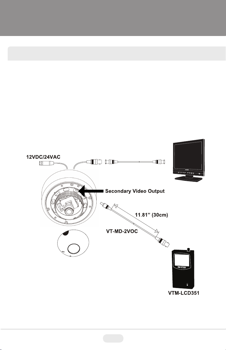
CONNECTIONS
• Power connection: 12VDC or 24VAC dual input.
• All Mighty Dome cameras come standard with a secondary video output. The
secondary video cable (VT-MD-2VOC) is included in the box.
VTM-LCD
7
Page 10

LENS ADJUSTMENT
1) Remove the Gimbal cover from the Gimbal base.
2) Loosen Zoom & Focus screws and make necessary adjustments as shown.
Field of view: Telephoto(T) to Wide(W)
Focus: Near(N) to infinity( )
3) OSD Joystick Control
4) Reattach the gimbal cover to the gimbal base.
3
OSD Joystick
Control
8
8
Page 11

INFINITE AXIS GIMBAL ADJUSTMENT
Rotation and “Friction Hold” Placement
The Gimbal mechanism yields maximum rotation and placement as shown below.
9
Page 12

WDR Mighty Dome Features
CMOS image sensor:
- Provides the best quality image without any blooming or vertical smear even under the spot light.
Pixim’s DPS technology:
- Offers unparalleled image quality across all lighting conditions especially in high -contrast
environments such as indoor and outdoor elements combined in the same field of view, or other
extreme bright & dark lighting elements combined in the same image.
- Delivers natural color
- Offers high resolution of 700TVL
- Eliminates compromising image noise by blooming or vertical
- Eliminates color rolling of the NTSC system by line-lock synchronization (AC24V version)
- Offers on-screen menu
ICR mechanism:
- Enhances sensitivity about 10x at night time
- Can accept infrared light
24VAC/12VDC dual power design:
- Offers flexibility in installation
- Ensures reliability
Main features are:
• Pixim D8800C Seawolf Digital Imaging System CMOS
• 700 TVL High Resolution
• WDR - Wide Dynamic Range
• 3DNR - Three Dimensional Noise Reduction
• Secondary Video Output (Cable Included)
• OSD (On Screen Display) for Camera Function Setup
• Flush or Surface Mount
• Infinity Ball Mount for Any Viewing Angle
• UTP interface and Heater / Blower Options Available
• UTC Control - Serial Control over Coax
• 1” Conduit Knockout
• Indoor and Vandal/Waterproof Proof IP 686 Rated Models
Available
• Optional Extreme Cold (-60’F) Temperature Kit available
• Available in ivory or black
• Dual Voltage 12VDC & 24VAC
smear
10
Page 13

SETUP
OSD Menu Features/Setup
1 In the Menu
, buttons to move the menu, , buttons to change the settings and
Use
press
2 Entering Menu
Press
3 MAIN
Follow the chart below for submenu settings
button to select or enter. stands for MENU or ENTER button.
button longer for than 2 seconds on the back of the camera.
MENU Default Descriptions
EXPOSURE
DAY/NIGHT AUTO
3D NR Sets DEPTH of 3D NR.
LENS
SELELT
SELECT
PICTURE
CONTROL
SPECIAL
D-EFFECT Sets FREEZE, FLIP or D-PTZ.
EXIT Choose EXIT, SAVE AND EXIT or FACTORY SET.
Sets COLOR ROLL COMP., AE PREFERENCE, WDR CONTROL and
SENSE-UP.
Sets OFF, AUTO or NIGHT
FF – Day/Night is disabled and camera works as a normal color camera.
O
A
UT O – Camera switches DAY from/to NIGHT automatically.
N->D THRES, N<->D DELAY, BURST ON B/W can be set.
See DAY&NIGHT AUTO SETUP for detail.
N
IG H T – Forced to remove IR cut filter and switch to B/W.
Selects the lens type, DC or MANUAL.
DC
I
n su b-me n u, A ccu r a te Fo c us ca n b e set by f unc tio n of FO C US
AD J …
Sets WHITE BALANCE, COLOR SELECT, SHARPNESS, SATURATION,
GAMMA.
Sets MOTION, PRIVACY MASK, SYNC, LANGUAGE, VIDEO STANDARD,
RS485 CONTROL.
button stands for MENU or ENTER.
11
Page 14

OSD Menu Features/Setup
4 EXPOSURE
To enter EXPOSURE menu, press button at MAIN>EXPOSURE.
EXPOSURE Default Descriptions
EXPOSURE Descriptions
<WDR MID> Medium level of the dynamic range control for each PRESETs.
WDR HIGH Increases the dynamic range control. Some highlight area may washed out.
COLOR
ROLL
CUSTOM... Provides more flexible compensation other than WDR MID, WDR LOW, WDR HIGH
COMP.
BLC...
WDR LOW Decreases the dynamic range control.
AE
PREFRENCE
WDR
CONTROL
SENSE-UP AUTO
OFF
Compensates the brightness of main object against the bright back light.
A zone out of CTR SPOT, UPPER1/3, MIDDLE1/3, LOWER1/3 can be set.
Dynamic range control is inoperative if EXPOSURE is set to BLC.
HIGHLIGHTS
MEDIUM
In NTSC system, the entire color tone on the monitor may continuously
show reddish and greenish.
OLOR ROLL COMP. - Reduces the color rolling under the fluorescent
C
lighting. (NTSC system only)
OFF – Does not compensate the color rolling.
ODE-M - Compensates the color rolling when a manual lens is used.
M
ODE-A - Compensates the color rolling when an auto iris lens is used.
M
Sets HIGHLIGHTS or SHADOWS
HIGHLIGHTS - Provides the best detail in the brighter areas. The darker
parts of the scene may under-expose.
HADOWS - Provides the best detail in the darker areas. It will reduce
S
the dynamic range and the brighter parts may overexpose.
OW - Produces an image that has better contrast but less dynamic
L
range and is suitable for indoor or low-contrast outdoor scenes.
ORMAL - Produces an image that has average contrast and is suitable
N
for indoor or low-contrast outdoor scenes.
EDIUM - Produces an image that has better dynamic range and is
M
suitable for a lobby or high-contrast outdoor scenes.
IGH - Produces an image that has best dynamic range but less
H
contrast and is suitable for high-contrast outdoor scenes.
USTOM - Provides more flexible compensation by ZONE, RANGE and
C
BIAS.
**When COLOR ROLLCOMP. is set to MODE-A, WDR CONTROL will
be fixed as LOW.
If SENSE-UP is set to AUTO, the maximum sense-up rate can be
limited to 2X-30FPS, 4X15FPS, 8X-18FPS, 16X-4FPS, 32X-2FPS or
64X-2FPS in SENSE-UP SETUP.
he integration frames vary automatically within the max. rate according
T
o the light level when light becomes low and DSS is operating. The
t
higher sense-up rate, the higher sensitivity but the slower refresh rate.
Some white dots may appear by sense-up due to the image sensor’s
long accumulation by a long shutter period.
12
Page 15

OSD Menu Features/Setup
IMPORTANT!!!
IMPORTANT!!!
5 DAY/NIGHT
To enter EXPOSURE menu, press button at MAIN>DAY/NIGHT>AUTO
DAY->NIGHT and NIGHT->DAY operations must be examined and verified at the final step
f the installation.
o
Block the lens for a few seconds for NIGHT mode and release and let it return to DAY mode.
If camera stays at NIGHT mode more than 10 seconds, increase N-->D THRES a little and repeat
the fore-mentioned steps.
If the scene is too dim or lens iris was adjusted too low (near close), it may not return to DAY.
DAY/NIGHT Default Descriptions
N-->D
THRES.
N<-->D
DELAY
BURST
ON
B/W
-->D THRES is a threshold level to switch from NIGHT to DAY.
N
Due to the nature of WDR the image level of the scene is controlled down
and the camera will not switch to DAY despite bright ambience.
3
Increase the value if it stays in B/W and is required to switch to DAY.
Too high of a value may make ICR repeat between NIGHT<-->DAY.
In that case, slightly reduce the value and try all of the above.
<-->D DELAY is time in seconds while the camera maintains its status before
N
D<-->N switches.
3
DELAY can avoid the unwanted/frivolous switching by a short term light.
(I.e. the light from the passing car)
URST ON B/W determines whether a color burst signal keeps output or
B
eliminated when camera switches to B/W.
If set to ON, B/W video signal contains color burst signal and is more
compatible with the color equipment but shows the same resolution as color
OFF
video.
If set to OFF, the color burst signal is removed from B/W video and shows
better resolution.
Rarely, a compatibility problem may occur with the color equipment.
13
Page 16

OSD Menu Features/Setup
6 3D NR
To enter EXPOSURE menu, press button at MAIN>3D NR
3D NR Default Descriptions
DEPTH 47
7 DC LENS or MANUAL LENS
To enter EXPOSURE menu, press button at MAIN>LENS SELECT>DC... or MANUAL...
DC/
MANUAL
AI LEVEL -24
FOCUS
ADJ...
Default Descriptions
Determines the depth of Three Dimensional Noise Reduction.
High value effectively reduces the noise but a comet effect may occur
for a fast moving object and vice versa.
Lower value opens the lens iris and increases the brightness and vice
versa. Too high of a value reduces the amount of incoming light and may
esult in the camera not returning to DAY from NIGHT.
r
OCUS ADJUST helps accurately adjust the focus regardless of DAY
F
r NIGHT. Sometimes the focus looks fine tuned at day time but out of
o
focus at night time. This function can eliminate the wrong adjustm ent of
focus.
14
Page 17

OSD Menu Features/Setup
8 PICTURE CONTROL
To enter the EXPOSURE menu, press button at MAIN>PICTURE CONTROL.
PICTURE
CONTROL
WHITE
BALANCE
COLOR
SELECT
SHARPNESS 2
SATURATION 1 High value makes color rich and vice versa.
GAMMA 45
9 SPECIAL
Factory
Default
Sets ATW Normal, ATW Desat, ATW Xtnd or MANUAL.
TW NORMAL – Compensates automatically in range of 2800K-7500K.
A
TW DESAT – Compensates automatically in range of 2000K-11000K.
A
ATW
NORMAL
COLOR1 Provides three color tones.
In the range of 2000-2800K and 7500-11000K, white balance is
gradually compensated.
TW Xtnd – Compensates automatically in range of 2000K-11000K.
A
ANUAL – White balance can be adjusted by either KELVIN or R/B
M
Increase or decrease the sharpness of the picture.
Too much sharpness can make image harsh and show more noise
as well as line flicker at the edge of the object in the picture.
Lower value improves the gain of the dark area but the image has less
contrast.
Higher value reduces the gain of the dark area and makes the image more
dark and contrastive. The image will lose the linearity with too high of a
value.
Descriptions
15
Page 18

OSD Menu Features/Setup
SPECIAL Default Descriptions
MOTION OFF
PRIVACY
MASK
SYNC INT 1 Sync is xed to INT1.
LAN GUAGE ENGLISH English is available only.
VIDEO
STANDARD
RS485
CONTROL
10 MOTION
Up to 4 motion areas and the sensitivity can be set. The sensitivity is applied for all zones equally.
When adjusting each zone, the zone border line changes color when pressing button. Green enables
enlarging, red enables reducing and white enables moving the zone with , , , buttons.
To exit MOTION ZONE SETUP, press button for 2 seconds.
NTSC Able to switch NTSC or PAL.
If it is set to ON and motion is detected , MOTION message will appear on
the monitor. See page 16, ‘MOTION ’ for settings.
If set to ON, it is available up to 6 privacy masks .
OFF
See page 11, ‘PRIVACY Area’ for settings.
Sets the communication parameters of RS -
485 for the remote control.
16
Page 19

OSD Menu Features/Setup
location with
An example of the mask when resizing with
An example of mask when relocating.
11 PRIVACY AREA
Up to 6 privacy areas can be programmed in size, position and mask color.
Use joystick to change size, position and mask color.
Right after pressing button at ON, the 1st
zone appears on top-left corner in orange.
The orange colored zone can be relocated in its
, , , buttons
Press button longer than 2 seconds to return to the previous menu.
, , , buttons.
Image after pressing button again. (1st
zone changes to blue)
Blue colored zone can be resized with ,
, , buttons.
17
Page 20

OSD Menu Features/Setup
RS485
12 RS485 CONTROL
CONTROL
CAMERA ID 1 Determines the camera’s identification (between 1 and 255)
ID DISPLAY OFF Displays camera title on top-left corner of the screen.
PROTOCOL VITEK VITEK is available only.
BAUD RATE 2400 Select 2400/4800/9600/19200 bps.
13 D-EFFECT
D-EFFECT Default Descriptions
FREEZE OFF Image freezes and shows the still image at the moment when set to ON.
FLIP OFF
D-PTZ Able to set digital zoom up to x12 and digital PAN/TILT if zoom ratio >1.
D-PTZ Default Descriptions
ZOOM 1 Digital zoom can set up to x12 x1 stands for ZOOM OFF.
PAN 0 Digital PAN can be set if ZOOM is set to >1.
TILT 0 Digital TILT can be set if ZOOM is set to >1.
Default Description
OFF (Normal display), H-FLIP (left & right flipped), V-FLIP (upside down
flipped), H/V-FLIP (left & right flipped and upside down flipped.)
Direction of joystick control should be flipped if V-flip is flipped to H/V-flip.
18
Page 21

OSD Menu Features/Setup
14 EXIT
MENU-2 Descriptions
EXIT Exits menu with discarding any changes.
SAVE AND EXIT Exits menu after saving the parameters.
FACTORY SET
Restores and saves all parameters of factory settings.
Camera resets and restarts automatically.
19
Page 22

HEADER
DIMENSIONS
Indoor Vandal
31
20
Page 23

HEATER / BLOWER SPECIFICATIONS
Specifications
HEADER
Power Supply
Power Consumption
Heater
Blower
Extreme Weather Heater - Optional
24 VAC
10W (Heater) / .7W (Blower)
On: at 41ºF / Off at 59ºF
Continuous 24 Hour Operation
On: -60ºF
21
Page 24

INDOOR MIGHTY DOME SPECIFICATIONS
HEADER
Specifications
Image Device
Effective Pixels
Scan Frequency
Synchronization
Horizontal Resolution
Sensitivity
S/N Ratio
White Balance
WDR Mode
Motion Detection
Digital Zoom
FLIP
Privacy Zone
Auto Iris Control
SLOW SHUTTER
Day & Night
Lens Options
NTSC PAL
Pixim D8800C Seawolf Digital Imaging System CMOS
758(H) X 540(V)
59.94HZ(V), 15.734K HZ(H) 50HZ(V), 15.625K HZ(H)
Internal / Line Lock (Phase Adjust)
700TVL
0.00008Lux at F1.2@40IRE, 32x (DSS + ICR mode)*
More than 52dB AGC OFF at 50IRE
2,000~11,000 K Automatic Tracking / AWB / MANUAL
[Low / Middle / High / Custom (User Adjustment)]
On / Off (4 Programmable Zone)
Up to X12 Digital Zoom
OFF / H-FLIP / V-FLIP / H/V-FLIP
On / Off (6 Programmable Zone)
DC Drive Iris Control
2 ~ 32X
Infrared Cut-Filter Removable built-in
F1.2 2.8-10mm DC Auto Iris IR Corrected ICR / F1.8 9-22mm
DC Auto Iris IR Corrected ICR / F1.5 18-50mm DC Auto Iris Corrected ICR
Video Output
Operating Power
Operating Condition
Dimensions (H x Dia.)
Weight (Camera)
Weight (Carton)
*Light Sensitivity may vary depending on lens specifications and capsule density and color
-4F ~ 122F (-20C ~ +50C), 85% RH. Max. Non-condensing
VBS 1 Vpp +/- 10%, 75ohm
12VDC / 24VAC 3 Watts / 220mAmp
4.45” x 5.71” (113mm x 145mm)
1lb / .46Kg
1.6lb / .72Kg
22
Page 25

VANDAL MIGHTY DOME SPECIFICATIONS
HEADER
Specifications
NTSC PAL
Image Device
Effective Pixels
Scan Frequency
Synchronization
Horizontal Resolution
Sensitivity
S/N Ratio
White Balance
WDR Mode
Motion Detection
Digital Zoom
FLIP
Privacy Zone
Auto Iris Control
SLOW SHUTTER
Day & Night
IP Rating
Pixim D8800C Seawolf Digital Imaging System CMOS
758(H) x 540(V)
59.94HZ(V), 15.734K HZ(H) 50HZ(V), 15.625KHZ(H)
Internal / Line Lock (Phase Adjust)
700TVL
0.00008Lux at F1.2@40IRE, 32x (DSS + ICR Mode)*
More than 50dB AGC OFF at 50IRE
2000~11000 K Automatic Tracking / AWB / Manual
[Low / Middle / High / Custom (User Adjustment)]
On / Off (4 Programmable Zone)
Up to X12 Digital Zoom
OFF / H-FLIP / V-FLIP / H/V-FLIP
On / Off (6 Programmable Zone)
DC Drive Iris Control
2 ~ 32X
Infrared Cut-Filter Removable Built-In
IP686
Lens Options
Video Output
Operating Power
Operating Condition
Dimensions (H x Dia.)
Weight (Camera)
Weight (Carton)
*Light Sensitivity may vary depending on lens specifications and capsule density and color
F1.2 2.8-10mm DC Auto Iris IR Corrected ICR / F1.8 9-22mm
DC Auto Iris IR Corrected ICR / F1.5 18-50mm DC Auto Iris IR Corrected ICR
VBS 1 Vpp +/- 10%, 75ohm
12VDC / 24VAC 3 Watts / 220 mAmp
-4F ~ 122F (-20C ~ +50C) 85% RH. Max. Non Condensing
4.45” x 6.73” (110mm x 170mm)
2.3lb / 1.04Kg
2.9lb / 1.32Kg
23
Page 26

VTM-LCDP Series
15” 17” and 19” Professional LCD Monitors
• 15” 17“ and 19” Professional LCD Display Panels
• Designed for continuous 24/7 operation
• VGA, Looping BNC Composite, and S-Video Video
Inputs. DVI & HDMI Inputs on 17“ & 19” Versions
• Resolution up to 1280 X 1024 (17” & 19”)
• Stereo Audio Input/Output
• VESA Standard Mounting
24
Page 27

CHRONO Series
8, and 16 Channel Digital Video
Recorders
• Highly efficient H.264 compression
• Built-in Data Redundancy
• Real-time recording and real-time playback
• System Setup Wizard and User Friendly GUI
• Multi-Resolution recording
• 4 Spot Output (8 &16 Channel)
• Highly efficient and stable proprietary Database
Structure
• Identical GUI for DVR and client viewer
• Built-in Point-of-Sales support
• Web clients & CMS (Central Management Software)
Included
• iPhone App
25
H.264
Page 28

LIMITED LIABILITY WARRANTY
VITEK products carry a three (3) year limited warranty. VITEK warrants
to the purchaser that products manufactured by VITEK are free of any
rightful claim of infringement or the like, and when used in the manner
intended, will be free of defects in materials and workmanship for a
period of three (3) years, or as otherwise stated above, from the date of
purchase by the end user. This warranty is non-transferable and extends
only to the original buyer or end user customer of a VITEK Authorized
Reseller.
The product must have been used only for its intended purpose, and
not been subjected to damage by misuse, willful or accidental damage,
caused by excessive voltage or lightning.
The product must not have been tampered with in any way or the guarantee will be considered null and void.
This guarantee does not affect your statutory rights.
Contact your local VITEK Reseller should servicing become necessary.
VITEK makes no warranty or guarantee whatsoever with respect to
products sold or purchased through unauthorized sales channels. Warranty support is available only if product is purchased through a VITEK
Authorized Reseller.
28492 CONSTELLATION ROAD VALENCIA, CA 91355
WWW.VITEKCCTV.COM
 Loading...