

Vitek VTD-MV2RHET2812-B, VTD-MV2RHET2812, VTD-MV2HET2812-B, VTD-M2HET2812-B, VTD-M2RHET2812-B User Manual
Page 1
VITEK
MIGHTY DOME TRIO
2.1 Megapixel EX/HD-SDI/TVI/960H
All-in-One Dome Camera Series
• Sony 1/2.8” 2 MegaPixel “STARVIS” CMOS Image Sensor
• Up to 2.1 Megapixel with EX/HD-SDI, TVI, and 960H Video Output
• Up to 30fps live view @ 1080p
• MegaPixel IR Corrected 2.8-12mm Varifocal Lens
• Optional 35 Dynamic Infrared LEDs at 850nm enable viewing in total darkness up to 120
feet
• True Day/Night by ICR - Dual Filter Switch
• Block & Polygon Privacy Masking with 24 Programmable Zones
• XD-DNR (2D+3D DNR) Noise Reduction
• OSD (On Screen Display) for Camera Setup
• Wired Remote Control with Secondary Video Output Included
• Ultra Versatile Design with Infinity Ball Mount for Any Viewing Angle
• Can be Flush or Surface mounted and Fits Perfectly in 4S Back boxes (Indoor Versions) /
4-11S Back boxes (Vandal Versions)
• IP68 Weather Resistance with Extreme Cold Temperature Kit Available (Vandal Versions)
• Extensive mounting options available
• 1” Conduit Knockout
• Available in Ivory or Black
• 12VDC/24VAC Dual Voltage Operation
Page 2

PACKAGE CONTENTS
Before installing the camera, please make sure that the following items are included in
the box:
1. Mighty Dome Trio Camera
2. Accessories
3. Wired remote controller
4. Instruction Manual & Mounting Template
If any of these materials are missing, please contact the vendor help desk immediately.
Available Models
Model Description
VTD-M2HET2812 Mighty Dome Trio Indoor EX-SDI/TVI/CVBS Camera
VTD-M2RHET2812 Mighty Dome Trio Indoor EX-SDI/TVI/CVBS IR Camera
VTD-MV2HET2812 Mighty Dome Trio Vandal EX-SDI/TVI/CVBS Camera
VTD-MV2RHET2812 Mighty Dome Trio Vandal EX-SDI/TVI/CVBS IR Camera
2
Page 3

DISCLAIMER
• While every effort has been made to ensure that the information contained in this
guide is accurate and complete, no liability can be accepted for any errors or
omissions.
• Our reserves the right to change the specifications of the hardware and software
described herein at any time without prior notice.
• No part of this guide may be reproduced, transmitted, transcribed, stored in a
retrieval system, or translated into any language in any form, by any means, without
prior written permission of Our.
• Our makes no warranties for damages resulting from corrupted or lost data due to a
mistaken operation or malfunction of the Speed Dome Cameras, peripheral devices,
or unapproved/unsupported devices.
3
Page 4
WARNING AND CAUTION
TO REDUCE THE RISK OF FIRE OR ELECTRIC SHOCK, DO NOT EXPOSE THIS PRODUCT TO RAIN
OR MOISTURE. DO NOT INSERT ANY METALLIC OBJECTS THROUGH THE VENTILATION GRILLS OR
OTHER OPENINGS ON THE EQUIPMENT.
EXPLANATION OF GRAPHICAL SYMBOLS
The lightning flash with arrowhead symbol, within an equilateral triangle, is intended to
alert the user to the presence of uninsulated "dangerous voltage" within the product's
enclosure that may be of sufficient magnitude to constitute a risk of electric shock to
persons.
The exclamation point within an equilateral triangle is intended to alert the user to the
presence of important operating and maintenance (servicing) instruction in the literature
WARNING
CAUTION
accompanying the product.
4
Page 5

FCC COMPLIANCE STATEMENT
THIS IS A CLASS A PRODUCT. IN A DOMESTIC ENVIRONMENT THIS
FCC INFORMATION: THIS EQUIPMENT HAS BEEN TESTED AND FOUND TO
COMPLY WITH THE LIMITS FOR A CLASS A DIGITAL DEVICE, PURSUANT TO
PART 15 OF THE FCC RULES. THESE LIMITS ARE DESIGNED TO PROVIDE
REASONABLE PROTECTION AGAINST HARMFUL INTERFERENCE WHEN
THE EQUIPMENT IS OPERATED IN A COMMERCIAL ENVIRONMENT. THIS
EQUIPMENT GENERATES, USES, AND CAN RADIATE RADIO FREQUENCY
ENERGY AND IF NOT INSTALLED AND USED IN ACCORDANCE WITH THE
INSTRUCTION MANUAL, MAY CAUSE HARMFUL INTERFERENCE TO RADIO
COMMUNICATIONS. OPERATION OF THIS EQUIPMENT IN A RESIDENTIAL
AREA IS LIKELY TO CAUSE HARMFUL INTERFERENCE IN WHICH CASE THE
USER WILL BE REQUIRED TO CORRECT THE INTERFERENCE AT HIS OWN
EXPENSE.
CAUTION: CHANGES OR MODIFICATIONS NOT EXPRESSLY APPROVED BY
THE PARTY RESPONSIBLE FOR COMPLIANCE COULD VOID THE USER'S
AUTHORITY TO OPERATE THE EQUIPMENT.
THIS CLASS A DIGITAL EQUIPMENT COMPLIES WITH CANADIAN ICES-003.
CET APPAREIL NUMÉRIQUE DE LA CLASSE A EST CONFORME À LA NORME
NMB-003 DU CANADA.
CE COMPLIANCE STATEMENT
WARNING
PRODUCT MAY CAUSE RADIO INTERFERENCE IN WHICH CASE THE USER
MAY BE REQUIRED TO TAKE ADEQUATE MEASURES.
5
Page 6

IMPORTANT SAFEGUARDS
1. Read these instructions.
2. Heed all warnings.
3. Follow all instructions.
4. Do not use this equipment near water.
5. Clean only with dry cloth.
6. Do not block any ventilation openings. Install in accordance with the manufacturer's
instructions.
7. Do not install near any heat sources such as radiators, heat registers, stoves, or
other equipment (including amplifiers) that produce heat.
8. Do not defeat the safety purpose of the polarized or grounding-type plug. A
polarized plug has two blades with one wider than the other. A grounding type plug
has two blades and a third grounding prong. The wide blade or the third prong is
provided for your safety. If the provided plug does not fit into your outlet, consult an
electrician for replacement of the obsolete outlet.
9. Protect the power cord from being walked on or pinched, particularly at plugs,
convenience receptacles, and the point where they exit from the equipment.
10. Only use attachments/accessories specified by the manufacturer.
11. Unplug this equipment during lightning storms or when unused for long periods of
time.
12. Refer all servicing to qualified service personnel. Servicing is required when the
equipment has been damaged in any way, such as power-supply cord or plug is
damaged, liquid has been spilled or objects have fallen into the equipment, the
equipment has been exposed to rain or moisture, does not operate normally, or has
been dropped.
13. CAUTION - THESE SERVICING INSTRUCTIONS ARE FOR USE BY QUALIFIED
SERVICE PERSONNEL ONLY. TO REDUCE THE RISK OF ELECTRIC SHOCK
DO NOT PERFORM ANY SERVICING OTHER THAN THAT CONTAINED IN THE
OPERATING INSTRUCTIONS UNLESS YOU ARE QUALIFIED TO DO SO.
Use Certified/Listed Class 2 power supply transformer only.
6
Page 7

TABLE OF CONTENTS
DISCLAIMER ................................................................................................................... 1
I. INSTALLATION AND CONFIGURATION....................................................................7
2.1 Installation ........................................................................................................................................ 7
2.2 Camera Control & Setup .................................................................................................................. 9
2.3 Varifocal, DC Auto Iris Lens Adjustments ................................................................................... 10
2.4 VIDEO OUT ..................................................................................................................................... 10
III. PROGRAM & OPERATION ...................................................................................... 11
Main Menu ............................................................................................................................................. 12
3.1 FOCUS ADJ .................................................................................................................................... 12
3.2 EXPOSURE ..................................................................................................................................... 12
3.2.1 LENS ................................................................................................................................................................................ 13
3.2.2 BRIGHTNESS .................................................................................................................................................................. 13
3.2.3 SHUTTER ........................................................................................................................................................................ 13
3.2.4 SENS-UP .........................................................................................................................................................................13
3.2.5 AGC .................................................................................................................................................................................. 13
3.3 BACKLIGHT .................................................................................................................................... 13
3.3.1 HLC .................................................................................................................................................................................. 14
3.3.2 BLC .................................................................................................................................................................................. 14
3.3.3 WDR ................................................................................................................................................................................. 15
3.4 DAY&NIGHT .................................................................................................................................... 15
3.4.1 AUTO ............................................................................................................................................................................... 15
3.4.2 COLOR ............................................................................................................................................................................. 15
3.4.3 B&W ................................................................................................................................................................................. 15
3.4.4 EXT. ................................................................................................................................................................................. 16
3.5 WHITE BAL ..................................................................................................................................... 16
3.5.1 AUTO ............................................................................................................................................................................... 16
3.5.2 AUTOext ........................................................................................................................................................................... 16
3.5.3 PRESET ........................................................................................................................................................................... 16
3.5.4 MANUAL .......................................................................................................................................................................... 17
3.6 DNR ................................................................................................................................................. 17
3.7 ADJUST ........................................................................................................................................... 17
3.7.1 COLOR GAIN ................................................................................................................................................................... 18
3.7.2 SHARPNESS ................................................................................................................................................................... 18
3.7.3 GAMMA ............................................................................................................................................................................ 18
3.7.4 MIRROR ........................................................................................................................................................................... 18
3.7.5 FLIP .................................................................................................................................................................................. 18
3.7.6 D-ZOOM ........................................................................................................................................................................... 18
3.7.7 ACE .................................................................................................................................................................................. 19
3.7.8 DEFOG ............................................................................................................................................................................. 19
3.7.9 SHADING ......................................................................................................................................................................... 19
3.7.10 PRIVACY ........................................................................................................................................................................ 19
3.8.1 DET WINDOW ................................................................................................................................................................. 21
3.8.2 SENSITIVITY ................................................................................................................................................................... 21
3.8.3 MOTION OSD .................................................................................................................................................................. 21
3.8.4 TEXT ALARM ................................................................................................................................................................... 22
3.8.5 SIGNAL OUT.................................................................................................................................................................... 22
3.9.1 COM. ................................................................................................................................................................................ 22
3.9.2 IMAGE RANGE ................................................................................................................................................................ 23
3.9.3 TVI OFFSET ..................................................................................................................................................................... 23
3.9.4 EXSDI ............................................................................................................................................................................... 23
3.9.5 FRAME RATE .................................................................................................................................................................. 23
3.9.6 FREQ ............................................................................................................................................................................... 23
7
Page 8

3.9.7 COLOR BAR .................................................................................................................................................................... 23
3.9.8 LANGUAGE ..................................................................................................................................................................... 23
3.9.9 CAM TITLE ....................................................................................................................................................................... 24
3.9.10 RESET ........................................................................................................................................................................... 24
Appendix A — SPECIFICATIONS ....................................................................................................... 25
Appendix B — DIMENSIONS .............................................................................................................. 27
8
Page 9
I. INSTALLATION AND CONFIGURATION
2.1 Installation
1) Dome Cover
Vandal Proof Domes - Use the provided Torx wrench to unscrew the vandal proof screws and remove the
•
dome cover.
Indoor Domes - Turn the dome cover to the left to remove the dome cover.
•
2) Flush Mount Installation:
Using four St4x30 screws, attach the flush mount base to a sturdy surface.
•
Optional flush mount decorator plate. Model: VT-MD-FMP
•
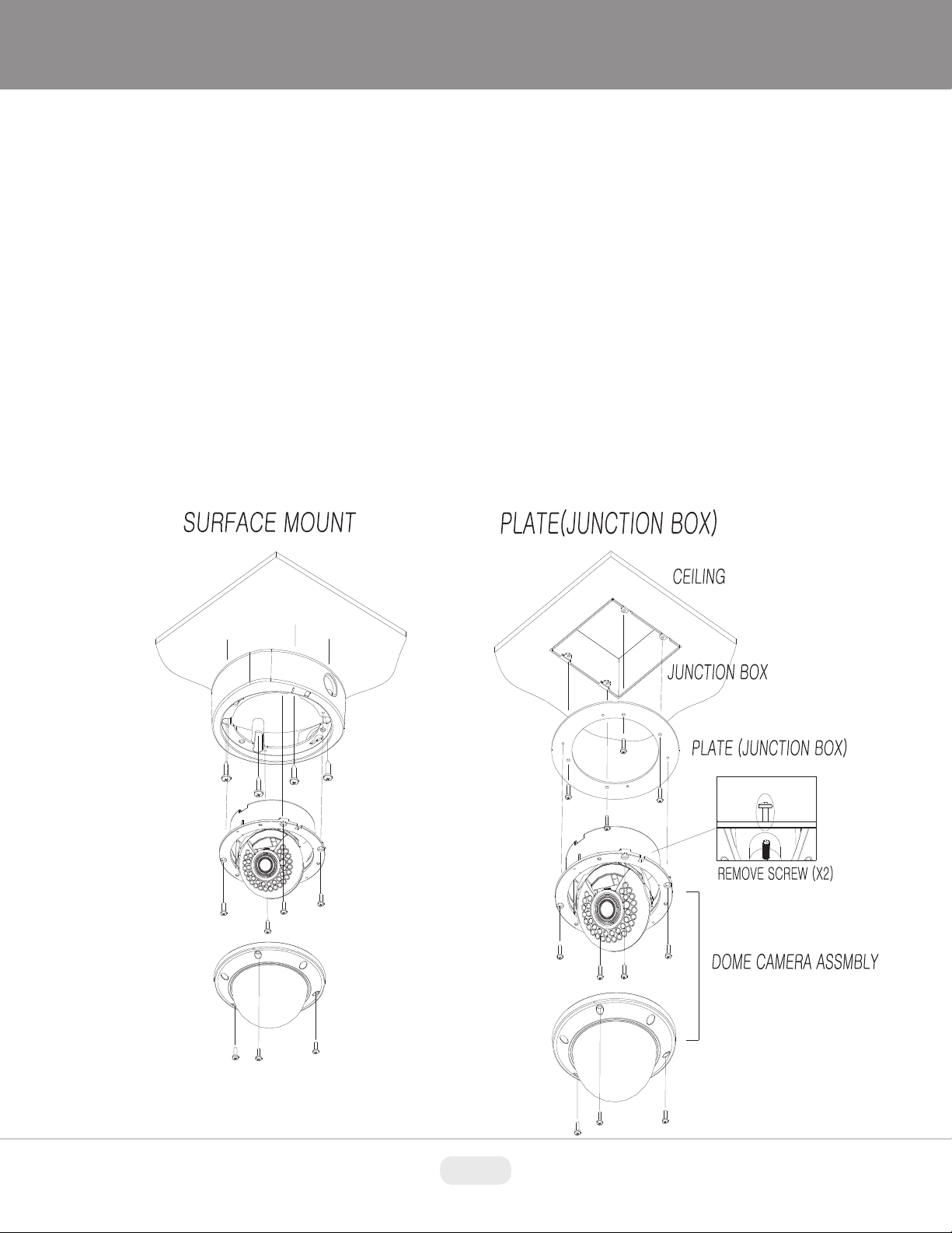
3) Surface Mount Installation:
Drill pilot holes at the mounting location using the provided mounting template. Using four St4x30 screws,
•
mount the surface mount housing to a sturdy surface. Using four ST4x12 (Indoor) screws or M4x10 (Vandalproof) screws, attach the flush mount base to the surface mount housing.
9
Page 10

10
Page 11

2.2 Camera Control & Setup
11
Page 12

TVI CVBS
2.3 Varifocal, DC Auto Iris Lens Adjustments
Loosen Zoom & Focus screws and make necessary adjustments as shown.
Field of View: Telephoto (T) to Wide (W)
Focus: Near (N) to Far (F)
2.4 VIDEO OUT
12
Page 13

III. PROGRAM & OPERATION
Main Menu
Sub Menu
Descriptions
FOCUS ADJ
OFF / ON
LENS
DC / MANUAL
BRIGHTNESS
10(0 ~ 20)
AUTO(OUTDOOR / INDOOR / DEBLUR)
MANUAL(1/25(30), ---, 1/30,000)
FLICKER
SENS-UP
X2 / OFF, ---, X32
AGC
9(0 ~ 10)
OFF
HLC
10(0~20) / COLOR(8kinds)
BLC
H(V)-POS(0~20) / H(V)-SIZE(0~20)
WDR
WEIGHT(LOW / MIDDLE / HIGH)
DAY&NIGHT
AUTO / COLOR / B&W / EXTERN / CDS
WHITE BAL
AWB / AUTO / AUTOext / PRESET / MANUAL
DNR
OFF / LOW / MIDDLE / HIGH
COLOR GAIN
12(0 ~ 20)
SHARNPESS
5(0 ~ 10)
GAMMA
0.5(0.45~0.7)
MIRROR
OFF / ON
FLIP
OFF / ON
D-ZOOM
1.0X(1.0X ~ 16.0X)
ACE
OFF / LOW / MIDDLE / HIGH
DEFOG
OFF / ON(MODE setting, LEVEL setting)
SHADING
WEIGHT(100% ~ 0%)
PRIVACY
2 Kinds : BOX(16ea), POLYGON(8ea)
OFF
DET WINDOW(4ea)
SENSITIVITY(5(0~10))
MOTION OSD
TEXT ALARM
SIGNAL OUT
COM.
CAM ID / BAUDRATE
IMAGE RANGE
FULL / COMP / USER
TVI OFFSET
OFF / ON
EXSDI
OFF / ON
FRAME RATE
1080P(25_30) / 720(25_30) / 720(50_60)
REQ
50HZ / 60HZ
COLOR BAR
OFF / ON
LANGUAGE
5kinds (ENG / CHN /CHN(S) / JPN / KOR)
CAM TITLE
RESET
EXPOSURE
BACKLIGHT
ADJUST
SHUTTER
MOTION
ON
SYSTEM
13
Page 14

Main Menu
MENU
FOCUS ADJ OFF
EXPOSURE
BACKLIGHT OFF
DAY&NIGHT EXT
WHITE BAL
DNR MIDDLE
ADJUST
MOTION OFF
SYSTEM
EXIT
3.1 FOCUS ADJ
Focus ADJ displays the input data from the FA Detector Mode in a Graphic Bar form.
This function provides convenience to the user by allowing a more accurate focusing by
utilizing a bar graph, there are 3 bars to adjust by Left, Center and Right. The left bar is
for low contrast areas, the center is mid contrast and the Right is for high contrast areas.
Adjust to the highest level possible without any Green showing in the bar graph
3.2 EXPOSURE
LENS DC
BRIGHTNESS 10 |||||||||||||
SHUTTER AUTO
SENS-UP X2
AGC 9 |||||||||||||
RETURN
EXPOSURE
14
Page 15

3.2.1 LENS
Using this function, you can control the screen brightness
DC : Select Auto Iris Lens
MANUAL : The shutter does not automatically move but is fixed to the maximum in this
mode.
3.2.2 BRIGHTNESS
Adjusts the video brightness.(0~20)
3.2.3 SHUTTER
AUTO : Select this mode to control the shutter speed automatically.
Shutter speed is automatically controlled depending on the brightness of the screen.
(OUTDOOR / INDOOR / DEBLUR)
MANUAL : You can select one of 12 options.
1/30(25, 1/60(50), 1/120(100), 1/250, 1/700, 1/1000, 1/1600, 1/2500, 1/5000,
1/7000, 1/10000, 1/30000
FLICKER : Select this when you experience picture flicker, this happen when there is a
clash with the installed lighting frequency.
3.2.4 SENS-UP
When it is night of dark, the camera automatically detects the light level and maintains a
clear picture. (OFF, X2, X4, X8, X16, X32)
3.2.5 AGC
The Higher the gain level, the brighter the screen but the higher the noise(0~9).
3.3 BACKLIGHT
Enable to directly compensate backlight in a desired area from a picture, and to view
the area more clearly.
15
Page 16

3.3.1 HLC
LEVEL 10 |||||||||||||
COLOR BLK
RETURN
BACKLIGHT
This function masks strong light to minimize white out due to over exposure and
preserve much of the on-screen details when the camera sees a strong light source.
LEVEL : 0 ~ 20
COLOR : BLACK, WHITE, YELLOW, CYAN, GREEN, MAGENTA, RED, BLUE
3.3.2 BLC
H-POS 8
V-POS 7
H-SIZE 3
V-SIZE 3
RETURN
BACKLIGHT
Backlight compensation
H-POS : 0 ~ 20
V-POS : 0 ~ 20
H-SIZE : 0 ~ 20
V-SIZE : 0 ~ 20
16
Page 17

3.3.3 WDR
Wide Dynamic Range.
WEIGHT : LOW, MIDDLE, HIGH
No support for CVBS.
WEIGHT MIDDLE
RETURN
BACKLIGHT
3.4 DAY&NIGHT
3.4.1 AUTO
Optimized for standard cameras without IR
3.4.2 COLOR
ANTI-SAT. 0 |||||||||||||
AGC THRES 3 |||||||||||||
AGC MARGIN 5 |||||||||||||
DELAY 3 |||||||||||||
RETURN
DAY&NIGHT
The picture is always displayed in color.
3.4.3 B&W
The picture is always displayed in black and white.
17
Page 18

3.4.4 EXT.
Optimized for IR Cameras
Anti Saturation
This function automatically controls the brightness for saturated object from the IR light.
It prevents saturation and expands dynamic range. Also saturation level can be
controlled.
ANTI-SAT. 0 |||||||||||||
RETURN
ANTI-SAT. 0 |||||||||||||
EXTERN SW LOW
DELAY 3 |||||||||||||
RETURN
DAY&NIGHT
DAY&NIGHT
3.5 WHITE BAL
Ability to set the WHITE BALANCE mode.
3.5.1 AUTO
Automatically tracks the changes of color temperature and continuously adjusts the
white balance.
3.5.2 AUTOext
AUTOext is used in larger color map than AUTO mode.
3.5.3 PRESET
To find the optimal luminance level for the current environment, point the camera
towards a sheet of white paper and press the Function Setup switch. If the environment
changes, readjust it.
18
Page 19

3.5.4 MANUAL
Select this to fine-tune White
Balance manually. Set White Balance first by using the C-TEMP mode. After that adjust
the R-GAIN & B-GAIN mode, fine-tune the white balance.
C-TEMP 5000K
R-GAIN 10 |||||||||||||
B-GAIN 10 |||||||||||||
RETURN
AWB
3.6 DNR
DNR reduces noise by amplifying gain in low light. (OFF, LOW, MIDDLE, HIGH)
3.7 ADJUST
19
Page 20

COLOR GAIN 12 |||||||||||||
SHARPNESS 5 |||||||||||||
GAMMA 0.5
MIRROR OFF
FLIP OFF
D-ZOOM 1.0X
ACE OFF
DEFOG OFF
SHADING OFF
PRAVACY
RETURN
ADJUST
3.7.1 COLOR GAIN
The setting range is 0 ~ 20. The smaller the setting value the smaller the color gain gets
and the image will lose most of the color.
3.7.2 SHARPNESS
Select a mode to adjust the image’s sharpness. Increase or decrease the level. Too
high of Sharpness more noise will appear in image. value.(0 ~ 20)
3.7.3 GAMMA
The setting range is 0.45 ~ 0.7. The closer to 0.7 the setting is, the darker it gets.
3.7.4 MIRROR
Flip an image horizontally.
3.7.5 FLIP
Flip an image vertically.
3.7.6 D-ZOOM
You can use a digital zoom of x1 ~ x16.
20
Page 21

3.7.7 ACE
This function is a local adaptive contrast enhancement. It uses a histogram analysis and
tone mapping method in pixels domain.
3.7.8 DEFOG
MODE AUTO
LEVEL MIDDLE
RETURN
DEFOG
You can use the defog mode to allow the camera to automatically detect the fog density
of the scene and display a clear image despite smog, or general poor visibility.
AUTO : Adjust the level automatically.
MANUAL : Depending on the defog level set by the user, adjust the clarity of
image.(LOW, MIDDLE, HIGH)
3.7.9 SHADING
It compensates for the dark area created by the outline of the lens. Compensation uses
2D gain table. User can control 0 ~ 100% compensation rate according to shading
weight.
3.7.10 PRIVACY
Mask an area you want to hide on the screen.
BOX OFF
POLYGON OFF
RETURN
PRIVACY
21
Page 22

ZONE NUM 0
ZONE DISPLAY ON
H-POS 12
V-POS 2
H-SIZE 3
V-SIZE 3
CB LEVEL 10 |||||||||||||
CR LEVEL 10 |||||||||||||
TRANS 2
RETURN
ZONE NUM 0
ZONE DISPLAY ON
POS0-X 80
POS0-Y 5
POS1-X 88
POS1-Y 5
POS2-X 88
POS2-Y 13
POS3-X 80
POS3-Y 13
CB LEVEL 10 |||||||||||||
CR LEVEL 10 |||||||||||||
TRANS 2
RETURN
BOX
POLYGON
ZONE NUM : You can select
up to 16(8 for polygon) PRIVACY areas.
ZONE DISPLAY : ON/OFF
H(V)-POS, H(V)-SIZE, POS0(1,2,3)-X(Y) : Adjust the size and position or the selected
area.
CB(CR) LEVEL : Determine area color.
TRANS : Adds or removes transparency from the masking area.
3.8 MOTION
22
Page 23

This product generates
signals each time an object movement is detected in the four areas of the screen so
efficient monitoring can be achieved.
3.8.1 DET WINDOW
WINDOW USE : You can
select up to 4 MOTION areas.
WINDOW ZONE : ON/OFF
DET H(V)- POS(SIZE) : Adjust the size and position or the selected area.
3.8.2 SENSITIVITY
DET WINDOW
SENSITIVITY 5 |||||||||||||
MOTION OSD OFF
TEXT ALARM OFF
SIGNAL OUT OFF
RETURN
WINDOW USE 0
WINDOW ZONE ON
DET H-POS 0
DET V-POS 0
DET H-SIZE 60
DET V-SIZE 34
RETURN
MOTION
DET WINDOW
Set the sensitivity of the motion detection. When you adjust to a higher level, the more
sensitive.
3.8.3 MOTION OSD
If an object moves in an area set by the user, it will be displayed on the screen as a box.
23
Page 24

3.8.4 TEXT ALARM
If an object moves in an area set by the user, it will be displayed on the screen as a
message.
3.8.5 SIGNAL OUT
Not supported.
3.9 SYSTEM
3.9.1 COM.
COM.
IMAGE RANGE FULL
TVI OFFSET OFF
EXSDI OFF
FRAME RATE 1080_30p
FREQ 60HZ
COLOR BAR OFF
LANGUAGE ENG
CAM TITLE OFF
RESET ON
RETURN
SYSTEM
24
Page 25

CAM ID 1
BAUDRATE 9600
RETURN
COM.
Not supported.
3.9.2 IMAGE RANGE
This is Digital output data scale mode for adjusting the black level.
Full : full digital data
COMP : scaling down mode
USER : user setting
3.9.3 TVI OFFSET
If you use HD-TVI, you should change TVI OFFSET to ON.
3.9.4 EXSDI
If you use EX-SDI, you should change EXSDI to ON.
3.9.5 FRAME RATE
Indicates the number of fps(frame per second) available for the video stream
configuration.(1080, 720)
3.9.6 FREQ
Select depending on NTSC or PAL.(60Hz, 50Hz)
3.9.7 COLOR BAR
Color bar pattern output.
3.9.8 LANGUAGE
The camera’s OSD is complimented by 5 languages.(English, Chinese, Chinese(s),
Japanese, Korean)
25
Page 26

3.9.9 CAM TITLE
This function allows the users to set the title of camera as well as the usage of on
screen display of the title.
3.9.10 RESET
Reset camera to factory settings.
26
Page 27

APPENDIX A — SPECIFICATIONS
Detailed Specifications VTD-M2HET2812 VTD-M2RHET2812
Image Sensor
Video Output
Resolution
Effective Pixels
Lens Type
Electronic Iris
DAY / NIGHT
Sensitivity
Dynamic Intensity Smart IR LEDs
WDR
DNR
Motion Detection
Privacy Mask
White Balance
FLIP
Advanced OSD Functions
Digital Zoom
Remote Control
Input Voltage
Power Consumption (12VDC)
Power Consumption (24VAC)
Operating Conditions
Weight
Dimensions (H x Dia.)
Sony® 1/2.8” STARVIS CMOS Image Sensor
EX/HD-SDI / TVI / 960H
2.1 MegaPixel (1920p x 1080p)
1920(H) x 1080(V)
MegaPixel IR Corrected 2.8-12mm Varifocal
1/60 ~ 1/100,000sec
Mechanical IR Cut Filter (True Day/Night)
0.15 lux (Color) / 0.03 lux (B/W)
N/A
XD-DNR (2D+3D DNR)
4 Programmable Zones
16 Box Zones / 8 Polygon Zones
ATW / PUSH / USER1 / USER2 / MANUAL / PUSH LOCK
H-Flip, V-Flip, H/V Flip
Defog, BLC/HLC, Dynamic IR, Privacy Masking,Motion Detection, Flip, LSC (Lens Shade Compensation)
Up to X16 Digital Zoom
Wired Remote Included
12VDC / 24VAC (Dual Voltage)
220 mA
110 mA
14°-122°F (-10°-50°C) < 80% RH
1lb / .46Kg
4.45” x 5.71” (113mm x 145mm)
0.15 lux (Color) / 0.03 lux (B/W) / 0 lux (IR ON)
35 850nm IR LEDs w/120’ Range
YES
220mA (IR OFF) / 480mA (IR ON)
110mA (IR OFF) / 240mA (IR ON)
27
Page 28

Detailed Specifications VTD-MV2HET2812 VTD-MV2RHET2812
Image Sensor
Video Output
Resolution
Effective Pixels
Lens Type
Electronic Iris
DAY / NIGHT
Sensitivity
Dynamic Intensity Smart IR LEDs
WDR
DNR
Motion Detection
Privacy Mask
White Balance
FLIP
Advanced OSD Functions
Digital Zoom
Remote Control
Water Resistance
Input Voltage
Power Consumption (12VDC)
Power Consumption (24VAC)
Operating Conditions
Weight
Dimensions (H x Dia.)
0.15 lux (Color) / 0.03 lux (B/W)
Defog, BLC/HLC, Dynamic IR, Privacy Masking,Motion Detection, Flip, LSC (Lens Shade Compensation)
220 mA
110 mA
Sony® 1/2.8” STARVIS CMOS Image Sensor
EX/HD-SDI / TVI / 960H
2.1 MegaPixel (1920p x 1080p)
1920(H) x 1080(V)
MegaPixel IR Corrected 2.8-12mm Varifocal
1/60 ~ 1/100,000sec
Mechanical IR Cut Filter (True Day/Night)
0.15 lux (Color) / 0.03 lux (B/W) / 0.03 lux (IR ON)
N/A
YES
XD-DNR (2D+3D DNR)
4 Programmable Zones
16 Box Zones / 8 Polygon Zones
ATW / PUSH / USER1 / USER2 / MANUAL / PUSH LOCK
H-Flip, V-Flip, H/V Flip
Up to X16 Digital Zoom
Wired Remote Included
IP-68
12VDC / 24VAC (Dual Voltage)
14°-122°F (-10°-50°C) < 80% RH
2.3 lb / 1.04Kg
4.45” x 6.73” (110mm x 170mm)
35 850nm IR LEDs w/120’ Range
220mA (IR OFF) / 480mA (IR ON)
110mA (IR OFF) / 240mA (IR ON)
28
Page 29

APPENDIX B — DIMENSIONS
INDOOR DOMES VANDAL DOMES
31
29
Page 30

LIMITED LIABILITY WARRANTY
VITEK products carry a three (3) year limited warranty. VITEK warrants to the purchaser
that products manufactured by VITEK are free of any rightful claim of infringement or the
like, and when used in the manner intended, will be free of defects in materials and workmanship for a period of three (3) years, or as otherwise stated above, from the date of
purchase by the end user. This warranty is nontransferable and extends only to the original
buyer or end user customer of a VITEK Authorized Reseller.
The product must have been used only for its intended purpose, and not been subjected to
damage by misuse, willful or accidental damage, caused by excessive voltage or lightning.
The product must not have been tampered with in any way or the guarantee will be considered null and void.
This guarantee does not affect your statutory rights.
Contact your local VITEK Reseller should servicing become necessary.
VITEK makes no warranty or guarantee whatsoever with respect to products sold or purchased through unauthorized sales channels. Warranty support is available only if product
is purchased through a VITEK Authorized Reseller.
28492 CONSTELLATION ROAD VALENCIA, CA 91355
WWW.VITEKCCTV.COM
Version 1.0
February 2016
 Loading...