

Page 1
VITEK
VITEK
VTC-402NZ
ENVI 2.1MP Vandal Resistant AFZ/
WDR IR Network Bullet Camera
FEATURES:
• 1/2.9” Sony® CMOS
• 2.1 MegaPixel With full 1080p/720p Output
• Up to 30fps live view@ 1920x1080 (1080p)
• MegaPixel IR Corrected 3-9mm (VTC-IR402NZ39) / 9-22mm (VTCIR402NZ922) Varifocal Lens
• Mechanical IR Cut Filter (True Day/Night)
• H.264/MJPEG Dual Streaming
• 16:9 Video format
• On-board Intelligence (OBI Technology) delivers Auto-Focus-Zoom by tracking
motion, then optically zooming in to that area of the frame
• 40 850nm IR LEDs with up to 150’ IR range
• Fully programmable advanced WDR
• Onvif Compliance
• Integrated Cooling Fan
• Standard SD memory card slot for Local recording
• Advanced OSD Functions: Motion Activated Pointing Zoom, Defog, Dynamic IR,
BLC/HLC, Motion Deblur, Pixel Defect Compensation, Title Set, Mirror, Flip
• Heavy Duty IP68 rated weather/vandal resistant aluminum construction
• 12VDC / 24VAC & PoE (Power over Ethernet) Operation
Specifications & installation procedure subject to change without notice.
Specifications & installation procedure subject to change without notice.
Visit www.vitekcctv.com for the most current information available.
Visit www.vitekcctv.com for the most current information available.
Page 2
ENVI Series: VTC-IR402NZ
1
1. Safety Precaution
Safety Precaution
To prevent fire or shock hazard, do not expose the unit to rain or moisture.
To prevent electric shocks and risk of fire hazards, do NOT use other than
specific power source.
Warning :
This equipment has been tested and found to comply with the limits for a Class
A digital device, pursuant to part 15 of the FCC Rules. These limits are designed
to provide reasonable protection against harmful interference when the equipment
is operated in a commercial environment . This equipment generates, uses, and
can radiate radio frequency energy and, if not installed and used in accordance with
the instruction manual, may cause harmful interference to radio communications.
Operation of this equipment in a residential area is likely to cause harmful
interference in which case the user will be required to correct the interference at
his own expense.
Caution :
Any changes or modifications in construction of this device which are not expressly
approved by the party responsible for compliance could void the user’s authority
to operate the equipment.
Mains power quality should be that of a typical commercial environment. If the user
of the model requires continued operation during power mains interruptions, it is
recommended that the model be powered from an uninterruptible power supply
(UPS) or a battery.
The symbol is intended to alert the user to the presence of important
operating and maintenance(servicing) instructions in the literature
accompanying the unit.
The symbol is intended to alert the user to the presence of uninsulated
"dangerous voltage" within the product’s enclosure that may be of
sufficient magnitude to constitute a risk of electric shock to persons .
CAUTION: TO REDUCE THE RISK OF ELECTRIC SHOCK,
DO NOT REMOVE COVER (OR BACK).
NO USER SERVICEABLE PARTS INSIDE.
REFER SERVICING TO QUALIFIED SERVICE PERSONNEL.
Page 3

ENVI Series: VTC-IR402NZ
2
Safety Precaution
NOTICE
The image used in this instruction manual are processed to help comprehension
and may differ from actual video of the camera.
Never open the device such as boards or lens.
The warranty becomes void if repairs are undertaken by unauthorized persons.
Maintenance and repair have to be carried out only by authorized service centers.
Use only a mild detergent to clean the housing.
The camera should never be operated beyond the technical specifications.
The camera should never be operated in water.
Avoid installing in areas where shock or vibration may occur.
Pay attention to safety when installing the connection cable and observe that the
cable is not subjected to heavy leads, kinks or damage and no moisture can get in.
This can lead to damage to the camera and void the warranty.
Page 4

ENVI Series: VTC-IR402NZ
3
2. Table of Contents
Table of Contents
1.! Safety Precaution .................................................................................................................... 1!
2.! Table of Contents .................................................................................................................... 3!
3.! General Description & Included Accessories .............................................................................. 8!
3.1.! VTC-IR402NZ Dimensions (Unit : mm) .......................................................................... 9!
4.! VTC-IR402NZ Layout ............................................................................................................. 10!
4.1.! Part Names ............................................................................................................... 10!
4.2.! Mount ....................................................................................................................... 10!
5.! VTC-IR402NZ Installation ....................................................................................................... 11!
5.1.! Mounting The Camera ............................................................................................... 11!
5.2.! Pan/Tilt Adjustment ................................................................................................... 12!
5.3.! Power Supply Connections ......................................................................................... 13!
6.! Operating Instructions ........................................................................................................... 14!
6.1.! Using OSD controller .................................................................................................. 14!
7.! Camera Software Installation .................................................................................................. 15!
8.! VTC-IR40NZ Features ............................................................................................................ 18!
9.! IP Installer: Introduction ........................................................................................................ 18!
10.! Installing and Uninstalling .................................................................................................... 18!
10.1.! Installing IP Installer .................................................................................................. 19!
10.2.! Uninstalling IP Installer .............................................................................................. 22!
11.! Using IP Installer ................................................................................................................. 24!
11.1.! Starting the Program ................................................................................................. 24!
11.2.! Search Product .......................................................................................................... 25!
11.3.! Automatic Network Setup ........................................................................................... 28!
11.4.! Using DHCP Server .................................................................................................... 30!
11.5.! Using PPPoE .............................................................................................................. 31!
11.6.! Updating Firmware .................................................................................................... 33!
11.7.! Filter Configuration .................................................................................................... 35!
11.8.! Live View .................................................................................................................. 36!
12.! ENVI Admin Menu ............................................................................................................... 38!
12.1.! Entering Admin Menu ................................................................................................. 38!
12.2.! Admin Menu Structure ............................................................................................... 39!
13.! Quick Configuration ............................................................................................................. 39!
13.1.! Step 1: Changing Server Name ................................................................................... 39!
13.2.! Step 2: Time Setup .................................................................................................... 39!
13.3.! Step 3: Network Setup ............................................................................................... 39!
Page 5

ENVI Series: VTC-IR402NZ
4
13.4.! Step 4: IPCCTVDNS.COM ........................................................................................... 40!
13.5.! Step 5: Recording Configuration ................................................................................. 40!
13.6.! Finish ........................................................................................................................ 40!
14.! System Configuration Menu ................................................................................................. 40!
14.1.! Server Name Setup .................................................................................................... 40!
14.2.! Date & Time .............................................................................................................. 41!
14.3.! Admin Password ........................................................................................................ 42!
14.4.! Access Control ........................................................................................................... 42!
14.5.! User Registration ....................................................................................................... 42!
14.5.1.! Add ................................................................................................................ 42!
14.5.2.! Edit ................................................................................................................ 44!
14.5.3.! Delete ............................................................................................................ 44!
15.! Network Configuration ......................................................................................................... 45!
15.1.! Static IP Configuration ............................................................................................... 45!
15.2.! DHCP Client Configuration .......................................................................................... 46!
15.3.! PPPoE Configuration .................................................................................................. 46!
15.4.! Network Ports ........................................................................................................... 47!
15.5.! Bandwidth Control Configuration ................................................................................. 47!
15.6.! View Network Status .................................................................................................. 48!
15.7.! Network Status Notify ................................................................................................ 48!
15.8.! IP-CCTV DNS Setup ................................................................................................... 50!
15.9.! Port Forwarding & UPnP ............................................................................................. 50!
15.10.!RTP/RTSP Setup ........................................................................................................ 51!
16.! Device Configuration ........................................................................................................... 52!
16.1.! Privacy Zone ............................................................................................................. 52!
16.2.! Camera & Motion ....................................................................................................... 55!
16.3.! Camera Configuration ................................................................................................ 57!
16.3.1.! Rate Control Mode ........................................................................................... 58!
16.3.2.! Image Quality Setup ........................................................................................ 59!
16.4.! Accessing the camera setup menu .............................................................................. 60!
16.5.! Direct Control menu ................................................................................................... 61!
16.6.! Advanced Camera OSD menu ..................................................................................... 65!
16.7.! SMART MOTION ZOOM (Detail Function Description) ................................................... 67!
16.8.! POINTING ZOOM (Detail Function Description) ............................................................ 68!
16.9.! DI (Sensor Input) / DO (Alarm Output) ....................................................................... 69!
17.! Advanced Configuration ....................................................................................................... 70!
17.1.! Advanced Services ..................................................................................................... 71!
17.1.1.! E-mail Service Configuration ............................................................................ 72!
17.1.2.! FTP (Buffered) Service Configuration ................................................................ 75!
Page 6

ENVI Series: VTC-IR402NZ
5
17.1.3.! FTP (Periodic) Service Configuration ................................................................. 77!
18.! Recording Configuration for Cameras with SD card ................................................................ 79!
18.1.! SD / MicroSD Card Configuration ................................................................................ 79!
18.2.! Recording Configuration with SD card ......................................................................... 82!
19.! Utilities ............................................................................................................................... 84!
19.1.! System Log ............................................................................................................... 85!
19.2.! Save Configuration .................................................................................................... 85!
19.3.! Reboot ...................................................................................................................... 86!
19.4.! Factory Default .......................................................................................................... 86!
19.5.! System Update .......................................................................................................... 87!
20.! ENVI Series Viewer .............................................................................................................. 90!
20.1.! Introduction .............................................................................................................. 90!
20.2.! Key Features ............................................................................................................. 90!
20.3.! System Requirement for PC ........................................................................................ 90!
21.! Installing and Uninstalling .................................................................................................... 91!
21.1.! Installing ENVI Series Viewer ...................................................................................... 91!
21.1.1.! Installing on Web Browser ............................................................................... 91!
21.1.2.! Manual Installation .......................................................................................... 93!
21.2.! Uninstalling ENVI Series Viewer .................................................................................. 94!
21.2.1.! Uninstalling with Program Menu ....................................................................... 94!
21.2.2.! Uninstalling on Control Panel ............................................................................ 95!
22.! Starting ENVI Series Viewer ................................................................................................. 97!
22.1.! Control Bar ................................................................................................................ 97!
22.2.! Channel Control Bar ................................................................................................... 98!
22.3.! OSD Channels Buttons ............................................................................................... 98!
22.3.1.! Saving as Image File ....................................................................................... 98!
22.3.2.! Saving as Video File ......................................................................................... 99!
22.3.3.! Manual Recording .......................................................................................... 100!
22.3.4.! Instant Playback ............................................................................................ 100!
22.4.! Extended Features ................................................................................................... 101!
22.4.1.! Pausing Live Video ........................................................................................ 101!
22.4.2.! FPS Control ................................................................................................... 101!
22.4.3.! Flip Control ................................................................................................... 102!
23.! EN-V-R: Introduction ......................................................................................................... 102!
24.! Requirements for Installation ............................................................................................. 103!
24.1.! EN-V-R Versions ...................................................................................................... 103!
24.2.! System Requirement for PC ...................................................................................... 104!
25.! Installing EN-V-R ............................................................................................................... 105!
26.! Uninstalling EN-V-R ........................................................................................................... 108!
26.1.! Closing Active EN-V-R .............................................................................................. 108!
Page 7

ENVI Series: VTC-IR402NZ
6
26.2.! Executing Uninstaller ............................................................................................... 108!
27.! Components of EN-V-R Program ......................................................................................... 109!
27.1.! EN-V-R Configurator ................................................................................................ 109!
27.2.! EN-V-R Service ........................................................................................................ 109!
27.3.! EN-V-R Controller .................................................................................................... 109!
27.4.! EN-V-R System Tray Menu ....................................................................................... 110!
28.! Starting EN-V-R Configurator ............................................................................................. 110!
29.! Quick Start Guide .............................................................................................................. 112!
29.1.! EN-V-R Configurator User Interface ........................................................................... 112!
29.2.! Searching for IP Devices .......................................................................................... 114!
29.3.! Registering IP Devices ............................................................................................. 115!
29.4.! Viewing Live Video ................................................................................................... 117!
29.5.! Recording Video ...................................................................................................... 119!
30.! ENVI Smart Player ............................................................................................................. 123!
30.1.! Introduction ............................................................................................................ 123!
30.2.! Key Features ........................................................................................................... 123!
30.3.! System Requirement for PC ...................................................................................... 123!
31.! Installing and Uninstalling .................................................................................................. 124!
31.1.! Installing Smart Player ............................................................................................. 124!
31.1.1.! Manual Installation ........................................................................................ 124!
31.2.! Uninstalling Smart Player .......................................................................................... 126!
31.2.1.! Uninstalling on Program Menu ........................................................................ 126!
32.! Configuring & Viewing Player ............................................................................................. 136!
32.1.! Main Window View .................................................................................................. 137!
32.2.! Connecting to NVR Player ......................................................................................... 137!
32.3.! Creating a Group ..................................................................................................... 138!
33.! Searching Video ................................................................................................................ 139!
33.1.! Searching Video ....................................................................................................... 139!
33.2.! Daily Search ............................................................................................................ 140!
33.2.1.! Search Mode ................................................................................................. 140!
33.2.2.! GO to Time Position ...................................................................................... 140!
33.3.! Condition Search Mode ............................................................................................ 141!
33.3.1.! Advanced Search Mode .................................................................................. 141!
34.! Video Playback Controls ..................................................................................................... 143!
35.! Extra Features .................................................................................................................. 144!
35.1.! Window Control ....................................................................................................... 144!
35.2.! Recording Period ..................................................................................................... 144!
35.3.! Backup ................................................................................................................... 144!
35.4.! Snapshot ................................................................................................................. 146!
35.5.! Print ....................................................................................................................... 147!
Page 8

ENVI Series: VTC-IR402NZ
7
35.6.! Ratio Display ........................................................................................................... 147!
36.! EN-V-R Configuration ......................................................................................................... 148!
36.1.! System, Network Configuration ................................................................................. 148!
36.1.1.! Configuring System name .............................................................................. 148!
36.1.2.! System, Network Configuration - Admin password ........................................... 149!
36.1.3.! System, Network Configuration - Access Control .............................................. 149!
36.1.4.! System, Network Configuration - HTTP Port .................................................... 150!
36.1.5.! System, Network Configuration - IP-CCTV DNS ................................................ 150!
37.! IP-CCTV DNS Registration .................................................................................................. 151!
38.! IP-Device Registration ....................................................................................................... 157!
38.1.! IP-Device Registration (Manual) ................................................................................ 157!
38.2.! IP-Device Registration (Automatic) ........................................................................... 160!
IP-Device Modification ................................................................................................ 161!
38.3.! IP-Device Deletion ................................................................................................... 163!
38.4.! IP-Device Homepage ............................................................................................... 163!
38.5.! Camera Management ............................................................................................... 163!
38.5.1.! Configure Camera Name and Information ....................................................... 164!
38.5.2.! Camera Resolution, Quality ............................................................................ 166!
38.5.3.! Configure Camera Recording Condition ........................................................... 167!
38.5.4.! Alarm, Event Configuration ............................................................................ 169!
38.6.! User Management ................................................................................................... 171!
38.6.1.! User Registration ........................................................................................... 172!
38.6.2.! User Modification .......................................................................................... 173!
38.6.3.! User Deletion ................................................................................................ 173!
38.6.4.! Disk Setup .................................................................................................... 173!
38.6.5.! Disk Quota Modification and Deletion .............................................................. 174!
38.6.6.! Disk Mode Change ......................................................................................... 175!
38.7.! Utilities ................................................................................................................... 177!
38.7.1.! Email account Configuration ........................................................................... 178!
38.7.2.! About Program .............................................................................................. 179!
39.! Using EN-V-R Controller ..................................................................................................... 179!
40.! Connecting to EN-V-R ........................................................................................................ 180!
40.1.! PC with EN-V-R installed .......................................................................................... 180!
40.2.! PC without EN-V-R ................................................................................................... 182!
41.! Specifications .................................................................................................................... 183!
42.! Warranty .......................................................................................................................... 184!
Page 9
ENVI Series: VTC-IR402NZ
8
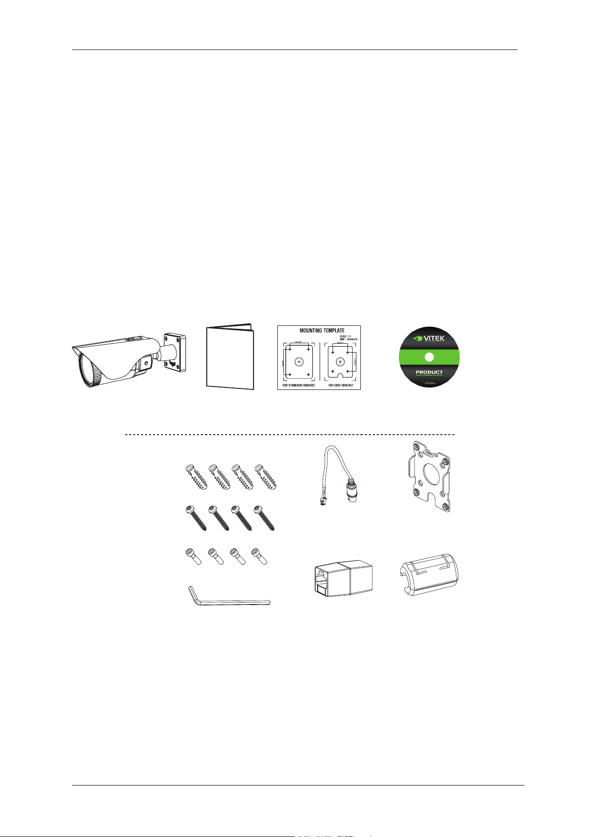
3. General Description & Included Accessories
This camera realizes the natural and crisp image as you see the scene in front
of you by adopting Auto Focus Full HD(1920x1080p) camera module.
General Description
Package Includes
VTC-402NZ Camera
General Operation
Instructions
Complete Installation and
Operation Instructions on CD
s7ITH)#2MECHANISM
- Enhances its sensitivity about 10x at night time
- Can accept infrared light
s6!#6$#DUALPOWER0O%0OWER/VER%THERNETDESIGN
- Offers the flexibility of installation
- Ensures the reliability
Mounting Template
Torque 7Rench:
3mm (1pc)
Video Sub-out
Cable (1pc)
!SSEMBLY3CREW
4 x 14mm (4pcs)
-OUNTING3CREW
4 x 30mm (4pcs)
Plastic Anchor:
6 x 30mm (4pcs)
Easy
Bracket
Coupler for
2*#ABLEPC
EMI Ferrite
Core (1pc)
Page 10
ENVI Series: VTC-IR402NZ
9
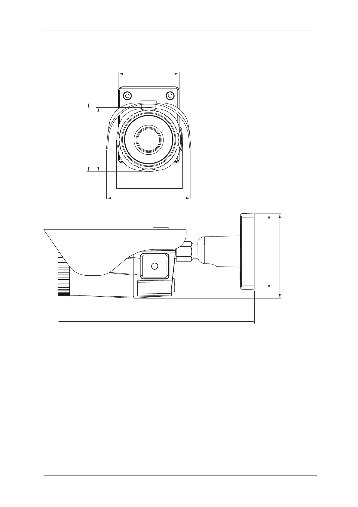
3.1. VTC-IR402NZ Dimensions (Unit : mm)
3.15
3.31
3.53
4.35
3.39
10.11
3.94
4.37
Page 11
ENVI Series: VTC-IR402NZ
10
4. VTC-IR402NZ Layout
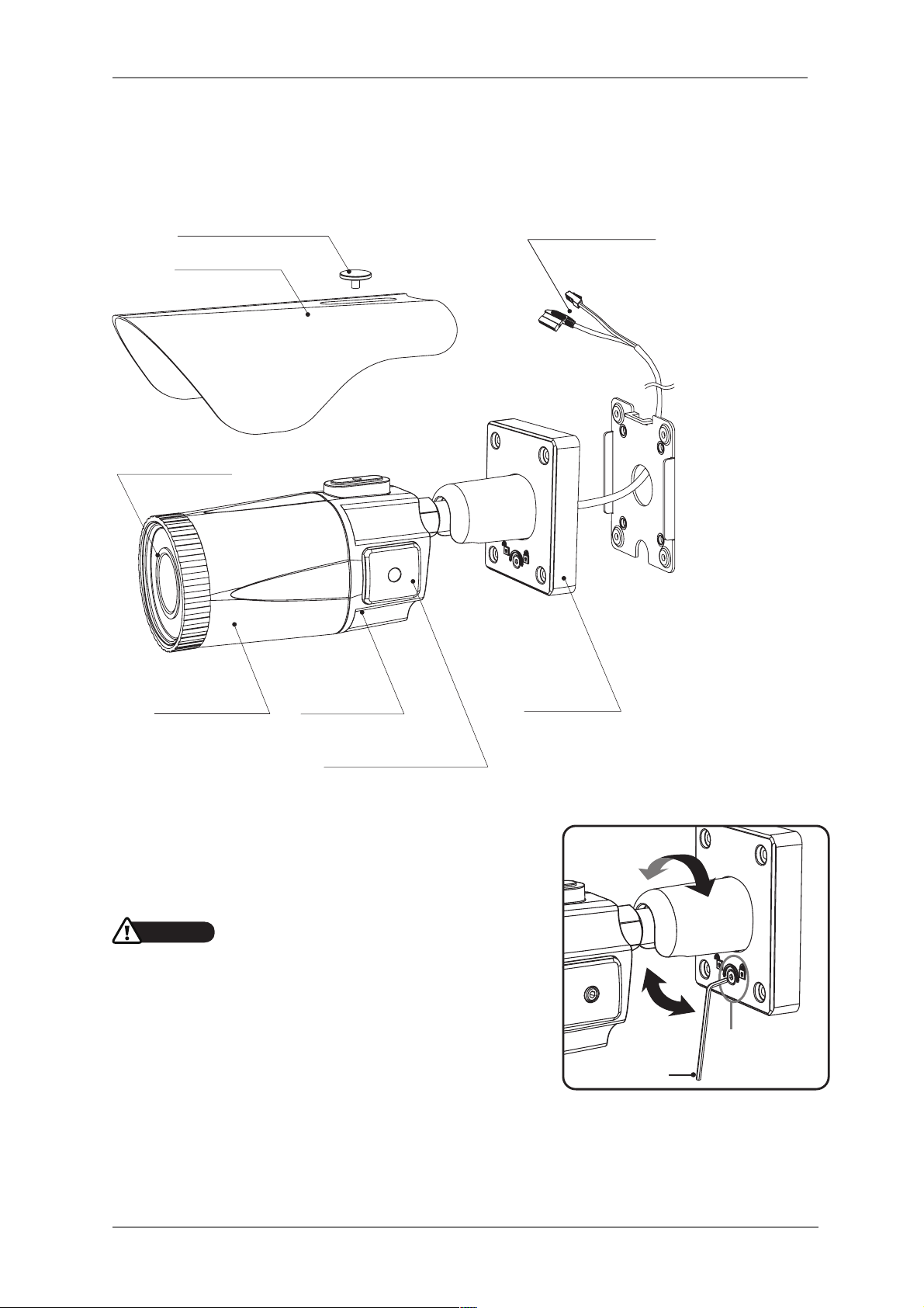
4.1. Part Names
4.2. Mount
• Adjustment of viewing angle with one-touch 3-Axis
bracket
DUAL WINDOW
SUNSHIELD BOLT
SUNSHIELD
FRONT CASE
OSD Setup
CONTROL COVER
BRACKET
REAR CASE
ETHERNET &
POWER CABLE
CAUTION
s%XTREMECARESHOULDBETAKEN./4TOSCRATCHTHE
WINDOWINFRONTOFLENSWHILEINSTALLINGORADJUSTING
THECAMERA
s#ARESHOULDBETAKENTHECABLEIS./4DAMAGED
KINKEDOREXPOSEDINAHAZARDOUSAREA
s$ONOTEXPOSETHECAMERADIRECTLYTOASTRONGLIGHT
SOURCESUCHASTHESUNORASPOTLIGHT
Torque
wrench
Lock/Unlock
Screw
Page 12
ENVI Series: VTC-IR402NZ
11
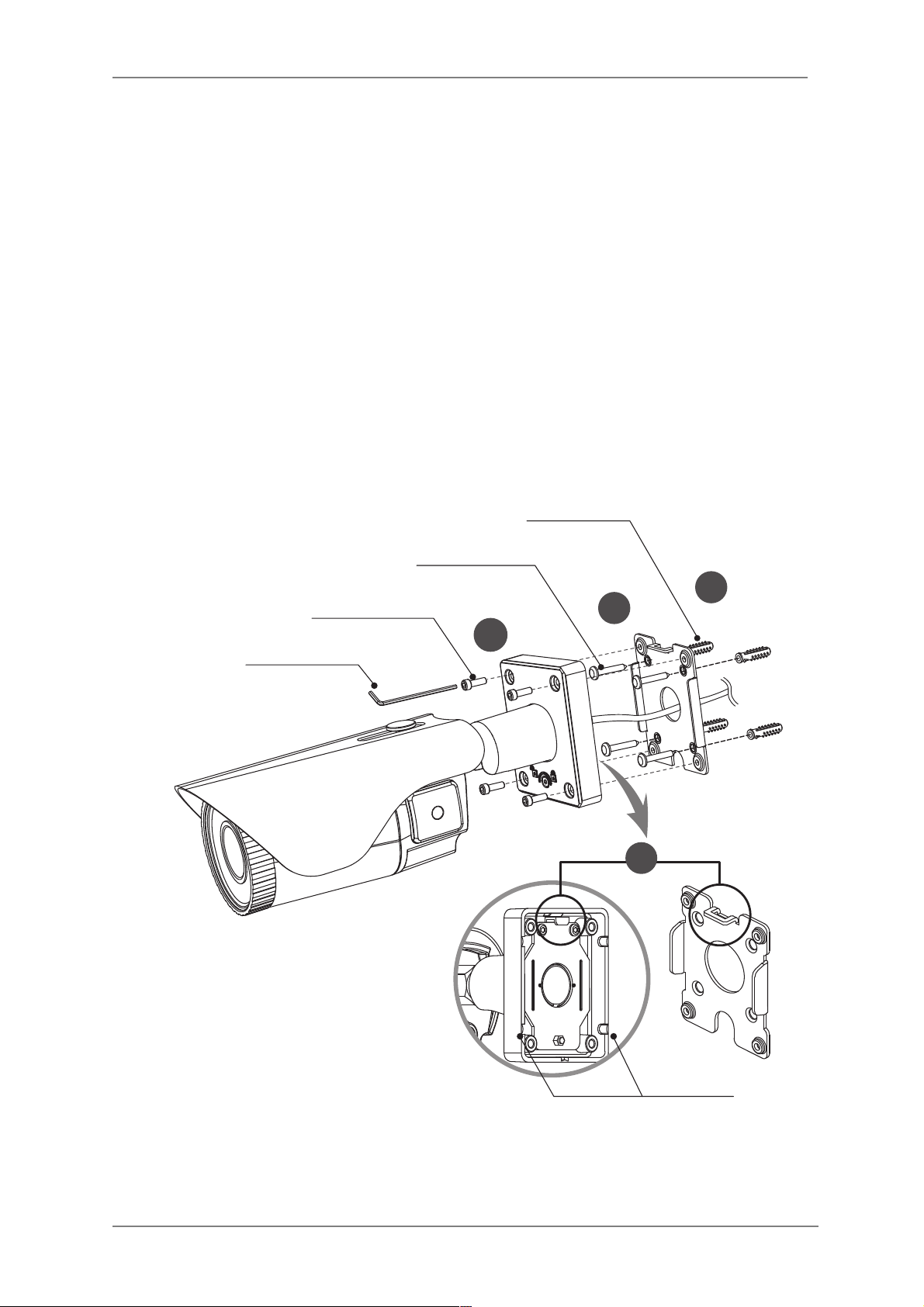
5. VTC-IR402NZ Installation
• Make sure power is not applied before installation.
5.1. Mounting The Camera
1. Locate the mounting template at the installation position and drill the ceiling or
wall if needed. (*The easy bracket can not be installed on the ceiling)
2. Place the easy bracket on pre-drilled position and attach using mounting
screws (4x30mm). Skip this step when an easy bracket is not installed.
3. Route the power cable to the area where connections are to be made.
Hook up the camera bracket with the easy bracket as illustrated below.
4. Affix the camera bracket using assembly screws (4x14mm).
5. Set the camera’s viewing angle.
6. Put the sunshield on the camera unit and tighten the sunshield-bolts.
Mounting Screw
: 4x30mm
Plastic Anchor
: 6x30mm
1
2
Torque Wrench
REAR VIEW
3
Cable exit
4
Assembly Screw
: 4x14mm
Page 13
ENVI Series: VTC-IR402NZ
12
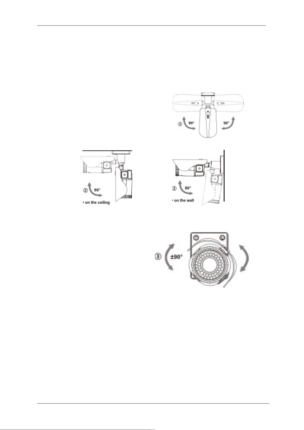
5.2. Pan/Tilt Adjustment
• Unlock the screw on the camera bracket using the torque wrench supplied
• Set the camera’s viewing angle then lock the screw on the bracket.
1. Tilt Adjustment
Pan is limited to +/- 90°.
2. Tilt Adjustment
Tilt is limited to 0°(2°) min ~ 90° max.
for wall (ceiling) installation respectively
with reference to the wall (ceiling) when
the inclination of camera module is 0°,
that is, the image is aligned horizontally.
3. Camera Rotation
Inclination limited (Horizontal image
alignment): Inclination limited to +/-90°
max.
Page 14
ENVI Series: VTC-IR402NZ
13
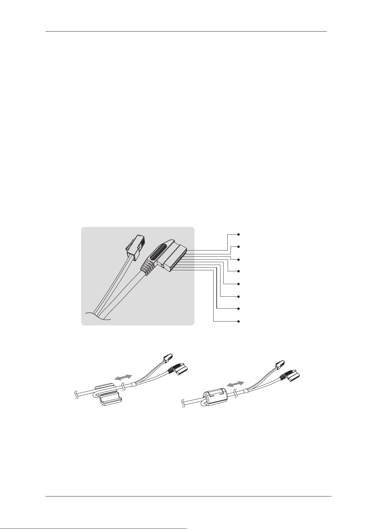
5.3. Power Supply Connections
• Make sure the power is removed before installation.
• After all connections are finished properly, follow the order for applying
power.
a) Plug the network cable into RJ-45 Ethernet Port.
If PoE is the unique power, there will be no need to connect Power terminal.
b) When DC12V or AC24V Local power is necessary, first connect the low voltage (DC12V or AC24V),
then plug the AC adapter to AC outlets to avoid an improper reset from power spike and damage
from a voltage surge with no load.
When PoE and Local power are connected, Local power has priority
Camera can work with either 24VAC or 12VDC, dual voltage power and PoE (IEEE Std. 802.3af).
Primary and secondary grounds are completely isolated to avoid the possible ground-loop problems.
RED(~24V+)
BLACK(~24V-)
GREEN(ALM-I)
BLUE(ALM-O)
GRAY(GND)
BROWN(AU-I)
GRAY(GND)
ORANGE(AU-O)
50mm
50mm
EMI Ferrite Core Connection
Page 15
ENVI Series: VTC-IR402NZ
14
6. Operating Instructions
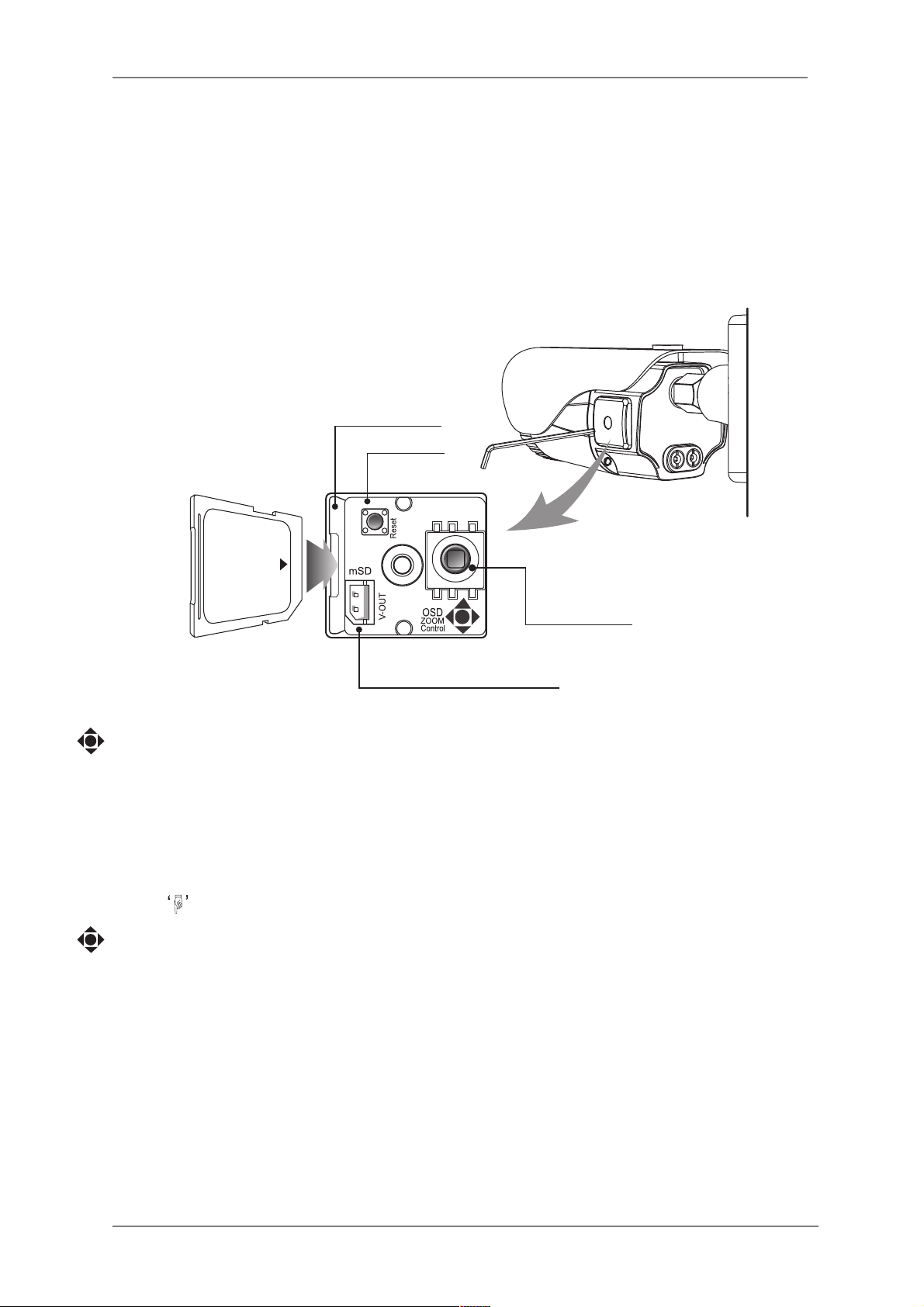
6.1. Using OSD controller
! Setup menu can be accessed and controlled by OSD control joy stick on the side of camera
unit.
! Five commands are available with the joy stick.
! The design of OSD could be different according to the Model.
Description of the joystick operation
1. SET Key (●) : Access to the menu or enter the setting. To enter the main menu, press the
Set Key down for about 1.5sec
2. UP/DOWN Key (▲/▼) : Choose the desired sub-menu and to move the cursor up or down
3. LEFT/RIGHT Key (◄/►) : Set up the value of the selected menu. Used to adjust the
desired menu selection and to move the cursor left or right.
4. Denotes long press down for about 2 seconds
Description of the DIGITAL ZOOM* adjustment
1. ▲ : Zoom In
2. ▼ : Zoom Out
3. ◄ : Focus Near
4. ► : Focus Far
Cover Open
OSD Control
Joy Stick
IP RESET
Standard
SD Card Slot
Video Sub-out Connector
Page 16
ENVI Series: VTC-IR402NZ
15
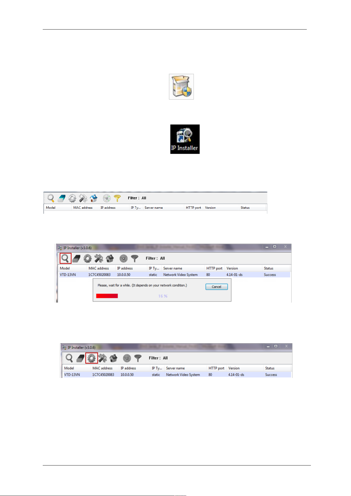
7. Camera Software Installation
1. Run IP Installer Software from the CD program on a computer that is on the same network
as the IP camera.
2. Start IP Installer, by double clicking the icon “IP Installer”
3. After the program has started, the main window of IP Installer program will appear on the
screen as shown below.
4. Search for the installed camera on the network by clicking the search product icon, the
camera should appear as the image below. The default IP address is 10.20.30.40
5. To assign an automatic IP address to this camera within the network, click the “Automatic IP
Setup” icon
6. Verify the Automatic IP address provided, enter the default password root and then click Set
as shown below.
Page 17
ENVI Series: VTC-IR402NZ
16
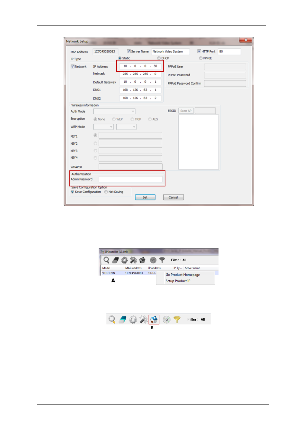
7. After the camera was configured by the program automatically, you will be able to get access
by
a) Right click over the camera information, “
Go Product Homepage
”
b) Click over the icon “
Connect Product Homepage
”
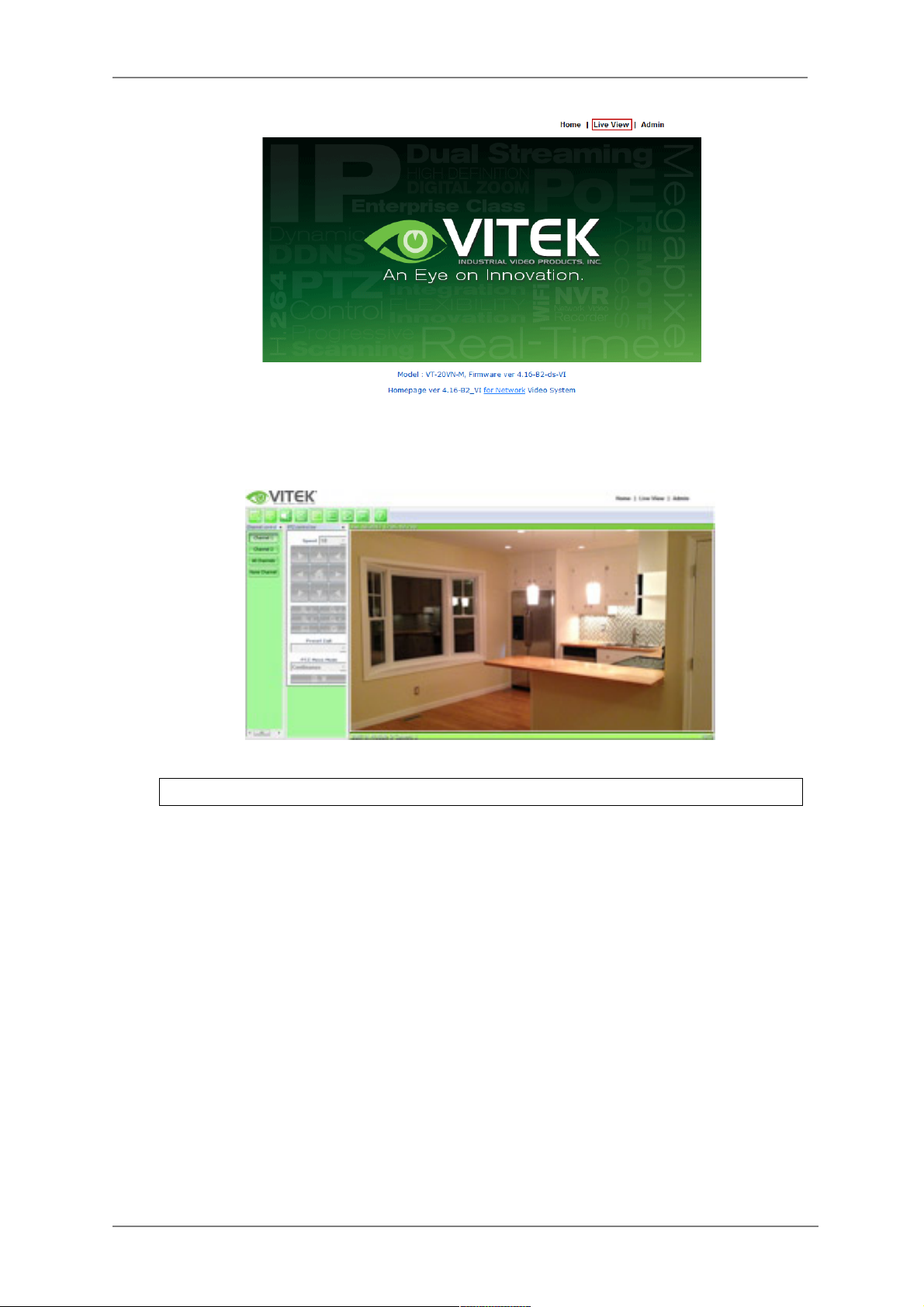
8. From the Home Page, you can “
Live View”
or administrate
“Admin”
the camera.
Page 18
ENVI Series: VTC-IR402NZ
17
On Live View you will be able to see live video from your camera.
NOTE: For more information, refer to
Section 12. ENVI Admin Menu on page 36
.
Page 19

ENVI Series: VTC-IR402NZ
18
8. VTC-IR40NZ Features
• Full HD, 2Mega Pixel Network CAMERA, 1920x1080(30p/25p)
• ONVIF & PSIA Conformance
• True WDR(Wide Dynamic Range)
• Improved Noise reduction with the enhanced 3D-NR
• VTC-IR402/NZ39: f=3~9mm, F1.2~F2.1 Day&Night zoom lens
(Optical 3x Auto focus zoom / Digital 32x zoom)
VTC-IR402/NZ922: f=9~22mm, F1.6~F2.3 Day&Night zoom lens
(Optical 2.4x Auto focus zoom / Digital 32x zoom)
• Focusig Status Indicator on Screen
- ★ (Blue) Focusing in process
- ★ (White) Focusing Completed
• Pointing Zoom which enables the flexible zooming at any area.
• Smart Motion Zoom in combining with Pointing Zoom.
• Selectable Scale down image to 720p mode
• Motion Detection, Privacy Mask, Defog, Sens-up, BLC/HLC, H/V/HV Flip, Motion Deblur,
Pixel Defect Compensation
• Lens Refresh / Lens Initializing Set / LSC(Lens Shade Compensation)
• Enhanced light Sensitivity by DSS technology
• H.264/MJPEG dual streaming
• Full duplex 2 way Audio, Alarm IN/OUT
• Max 30fps live view @ 1920x1080p
• Slot for Standard SD memory card verified up to 64GB
• Menu Control via either Local Joystick or WEB
• OSD menu & CVBS Video output BNC for easy installation & maintenance
• PoE(IEEE Std. 802.3af), 24VAC/12VDC
• Circuit protection against faulty connection in power polarity
• Isolated power supply against ground loop problem
• 40 850nm IR LEDs with up to 150’ IR range
• Dual Window, One-touch 3-Axis locking bracket, Easy Installation Pad
• Built-in cooling Fan & Heating function
• IP68 protection
9. IP Installer: Introduction
IP Installer is a proprietary utility program for Vitek IP products. It enables users of Vitek products
to search their network for any Vitek network camera, video server, or network video recorder no
matter what IP address it has. By using IP Installer, users will be able to facilitate network setup
process for Vitek products deployment.
5. Runs on Microsoft Windows operating system (XP, Vista, 7, 8)
6. Search for Network Cameras, Video Servers, and Network Video Recorders
7. Capable of firmware updating
8. Support automatic and manual IP setup
10. Installing and Uninstalling
** It’s recommended to install this program as an administrator **
Page 20
ENVI Series: VTC-IR402NZ
19
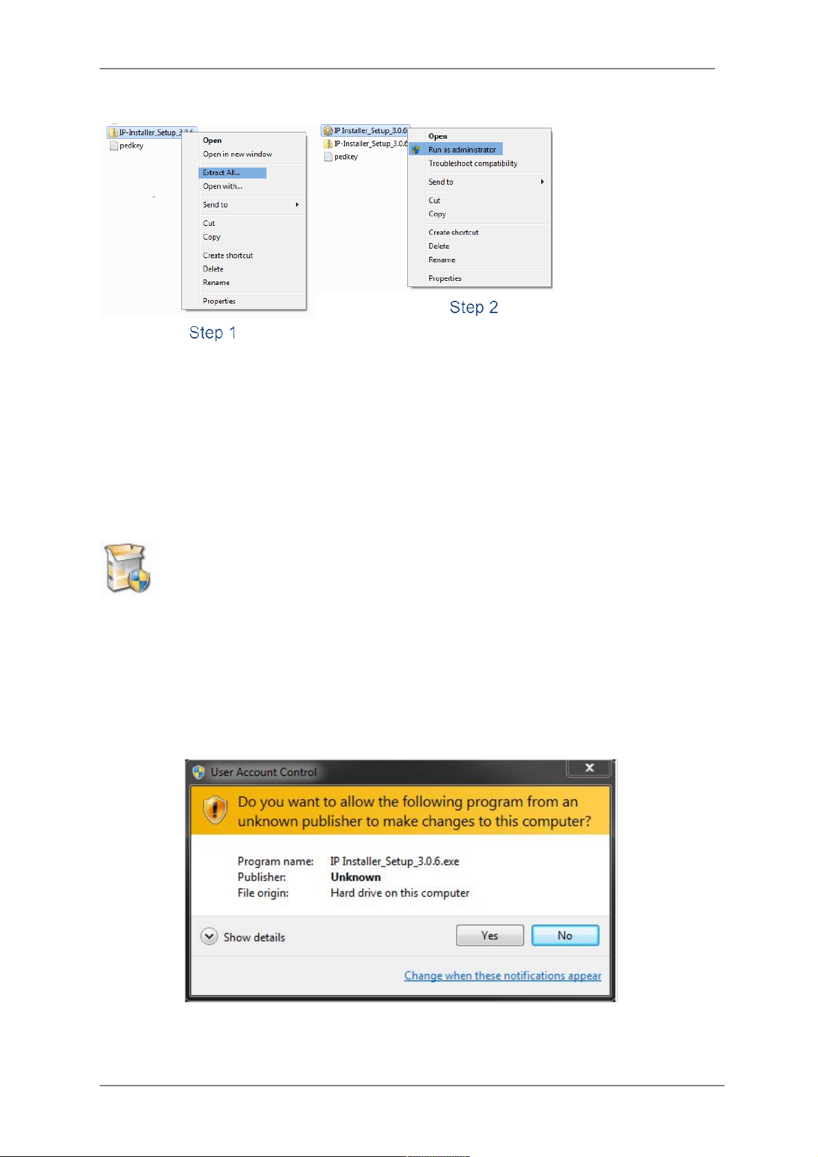
10.1. Installing IP Installer
If the program is started from the CD supplied with Vitek products, insert the CD in to CD/DVD tray
and check the installation file. If it is download or copied from the Internet or any other media,
locate the file from the PC’s hard drive. You will see the icon as shown with the file name IP
Installer_Setup_x.x.x.exe. The actual file name in your case may vary as the version changes.
Double click the icon to star installation.
You may be prompted to continue running the installation program.
Click Yes button, then the following window will be shown on the screen.
Page 21
ENVI Series: VTC-IR402NZ
20
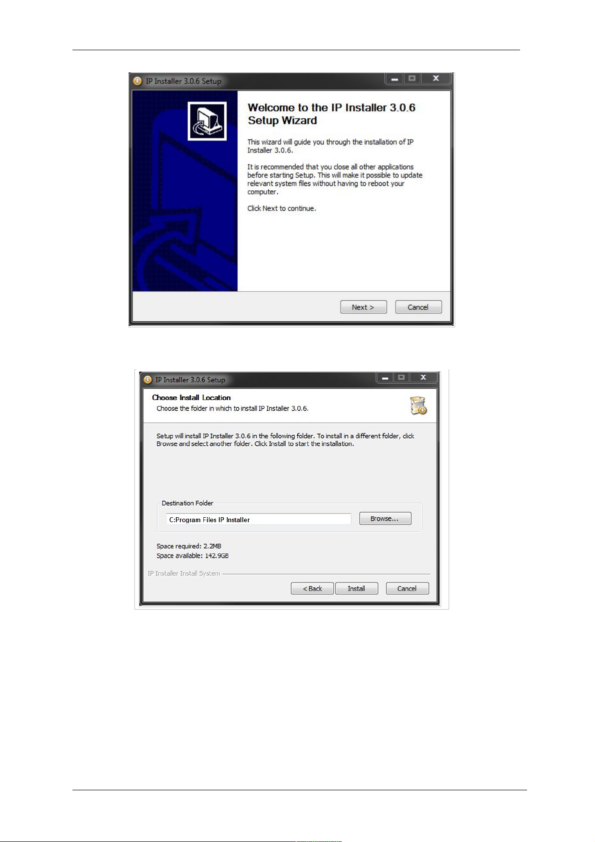
To continue the installation, click Next. The following window will be displayed for location to
install.
The default location for installation is C:\Program Files\IP Installer. It is recommended to install
in this folder, if you want to change it to a different location, click the Browse button to choose
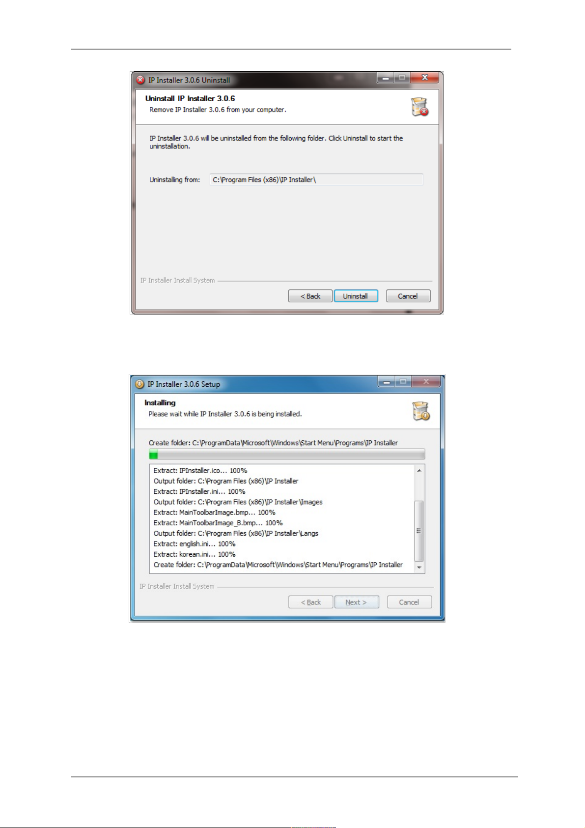
location. Now click the Install button. You will see the progress of the install as shown below.
Page 22
ENVI Series: VTC-IR402NZ
21
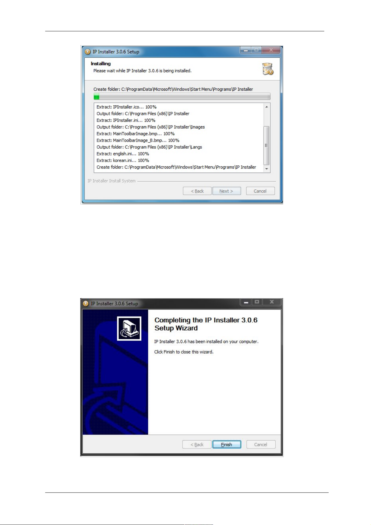
When the files are done copying, the following window will be shown. Click the Finish button to
complete the installation.
Page 23
ENVI Series: VTC-IR402NZ
22
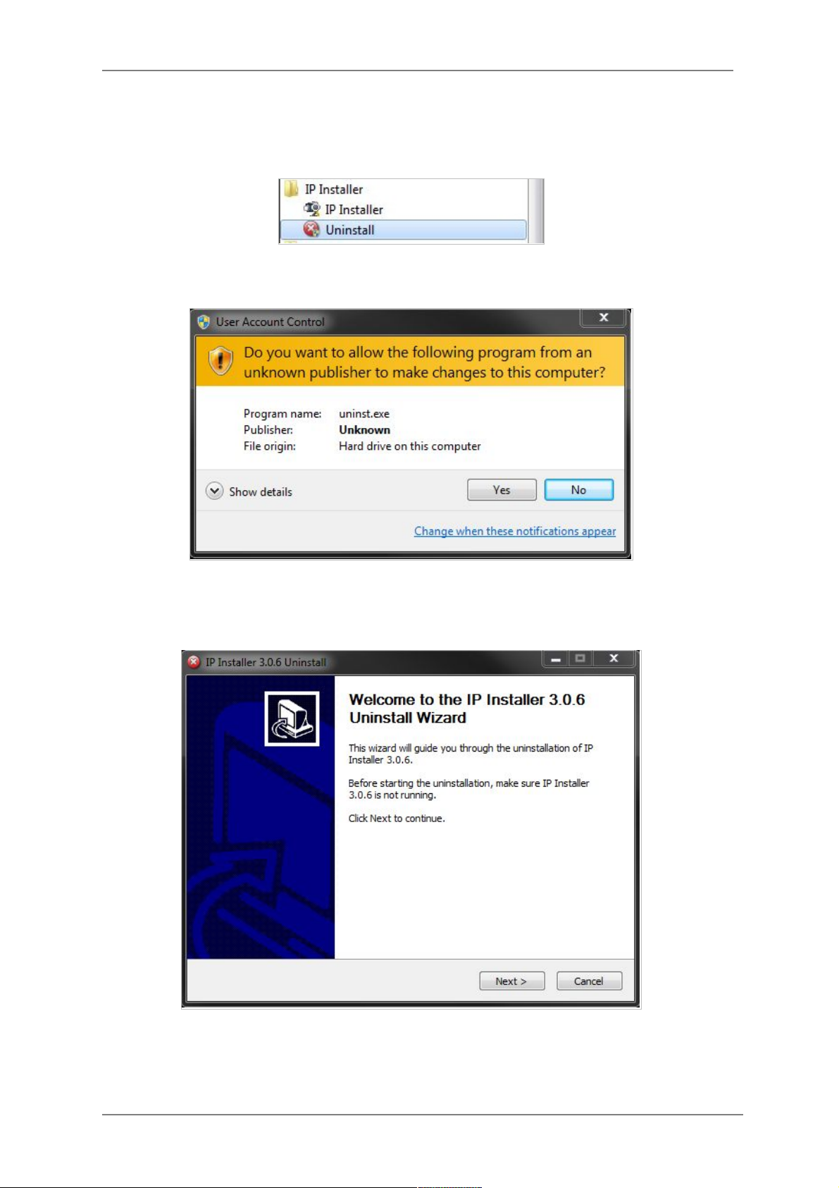
10.2. Uninstalling IP Installer
If you want to remove the IP Installer program from your PC, click Start > All Programs > IP
Installer > Uninstall.
You may be prompt to continue running the uninstall program.
Click on the Yes button, then the following window will be shown on the screen.
Click on the Next button and you will see the following window.
Page 24
ENVI Series: VTC-IR402NZ
23
Click on the Uninstall button to start removing the IP Installer program from your computer.
The following window will be displayed.
Click on the Finish button to close the window
Page 25

ENVI Series: VTC-IR402NZ
24
11. Using IP Installer
11.1. Starting the Program
Once IP Installer program has been installed on your computer, a shortcut icon
should be created on the desktop of your computer. You can start IP Installer by
double clicking the icon.
Or you can also start the program by clicking Start > All Programs > IP Installer > IP
Installer as shown below.
After the program has started, the main window of IP Installer program will appear on the
screen as shown below. There are no network devices shown, as it is the first time running the
program and nothing has been registered.
Search Product
Scan the network and shows the list of all the Vitek products that IP
Installer program found.
Clear Product List
Clear the Vitek products list created by searching the network.
Page 26
ENVI Series: VTC-IR402NZ
25
Automatic IP Setup
Configure the network setting of selected IP device in Automatic mode.
Manual IP Setup
Configure the network setting of selected IP device in Manual mode.
Connect Product
Homepage
Connect to the server homepage of the selected IP device.
Update Firmware
Update the firmware of the selected IP device.
Filter Configuration
Define the range of MAC and IP addresses to search.
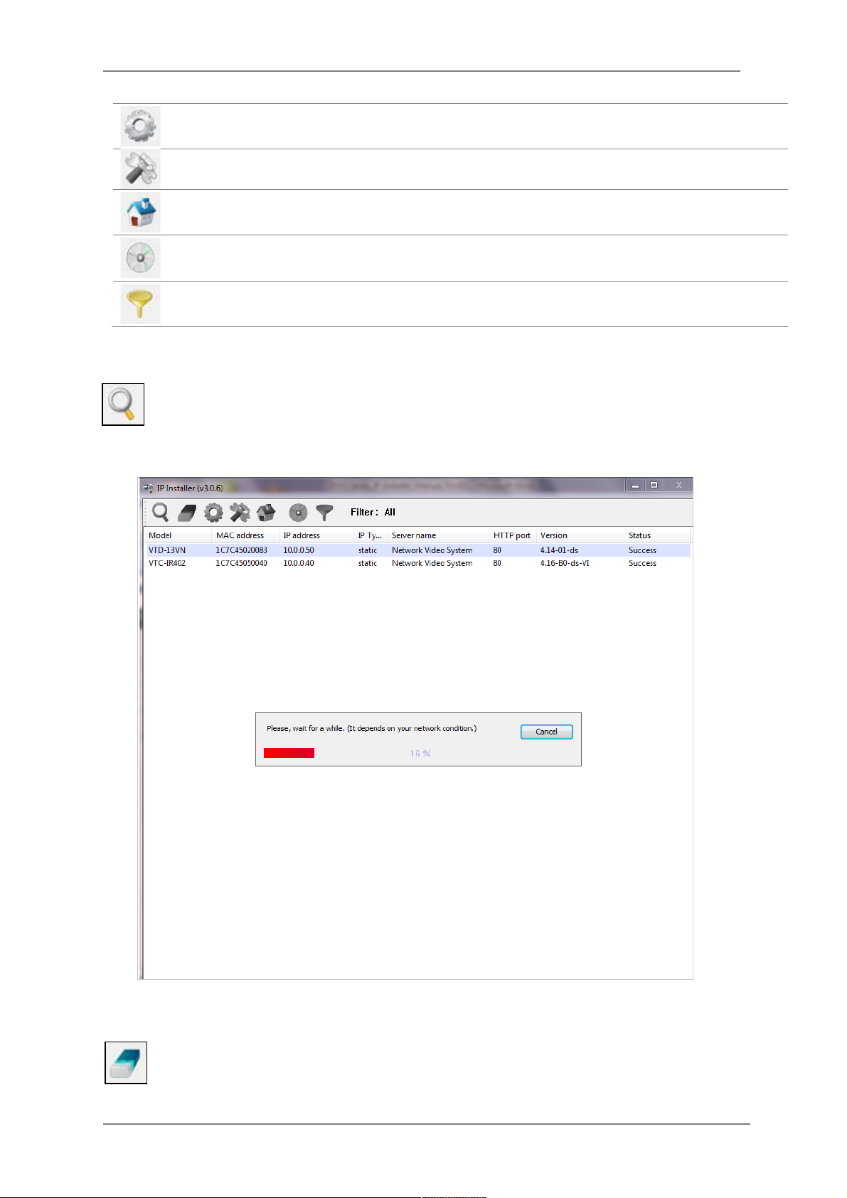
11.2. Search Product
Make sure that your Vitek products are powered and connected to the network, and then
click the Search Product button. A status window will pop up to show the progress of
the search. Wait until it reaches 100%, or you may press the Cancel button to stop the
search at any given time and proceed with the results made until that moment.
After searching is completed 100%, the IP Installer program will display the IP devices found.
If you want to clear the list of the IP Devices from the window, click Clear Product List
button from the Main Toolbar.
Page 27
ENVI Series: VTC-IR402NZ
26
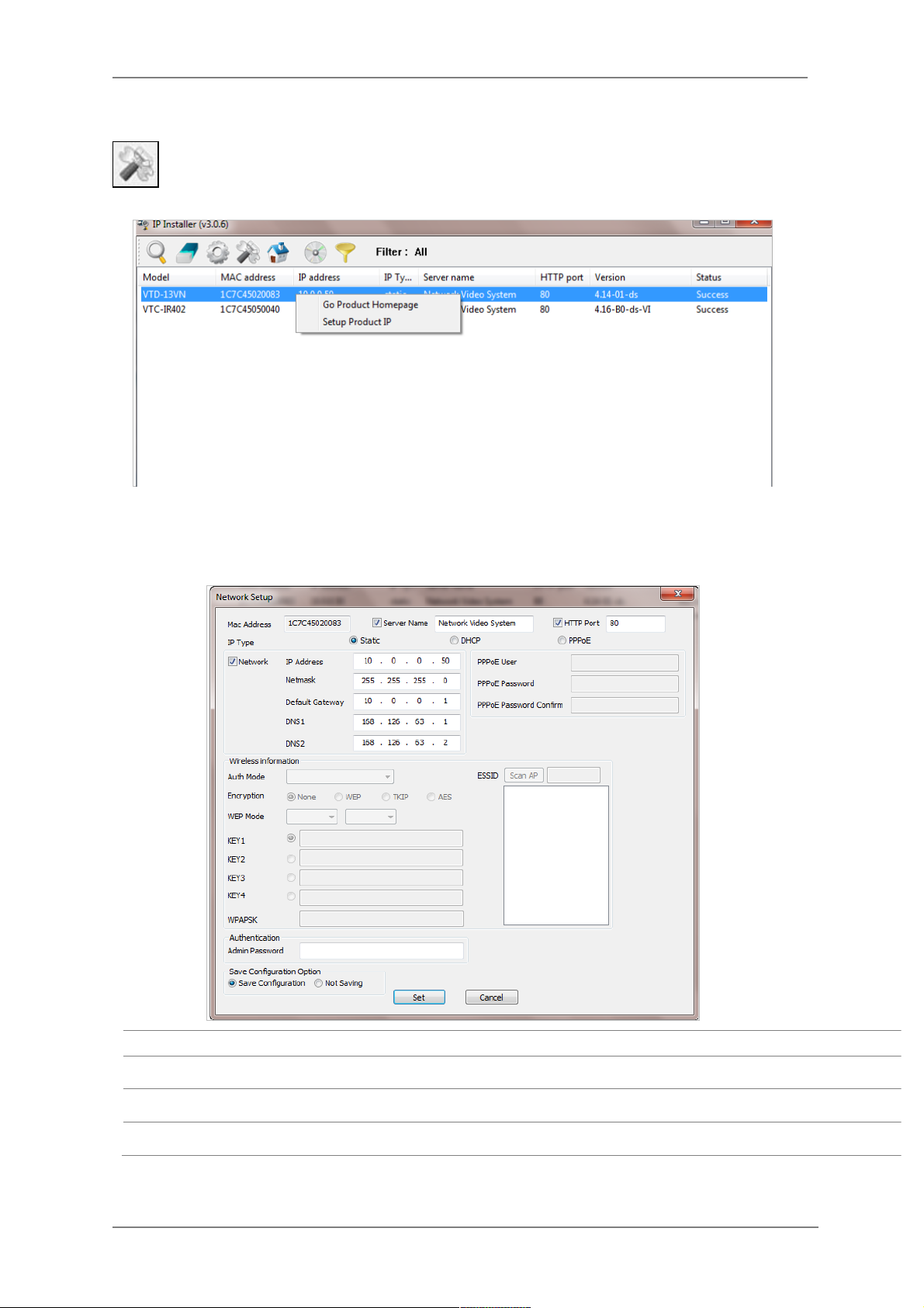
Manual Network Setup
Configuring the network parameters of the devices in the list can be started either by
highlighting and right clicking mouse button or by clicking Manual IP Setup button on
the main Toolbar.
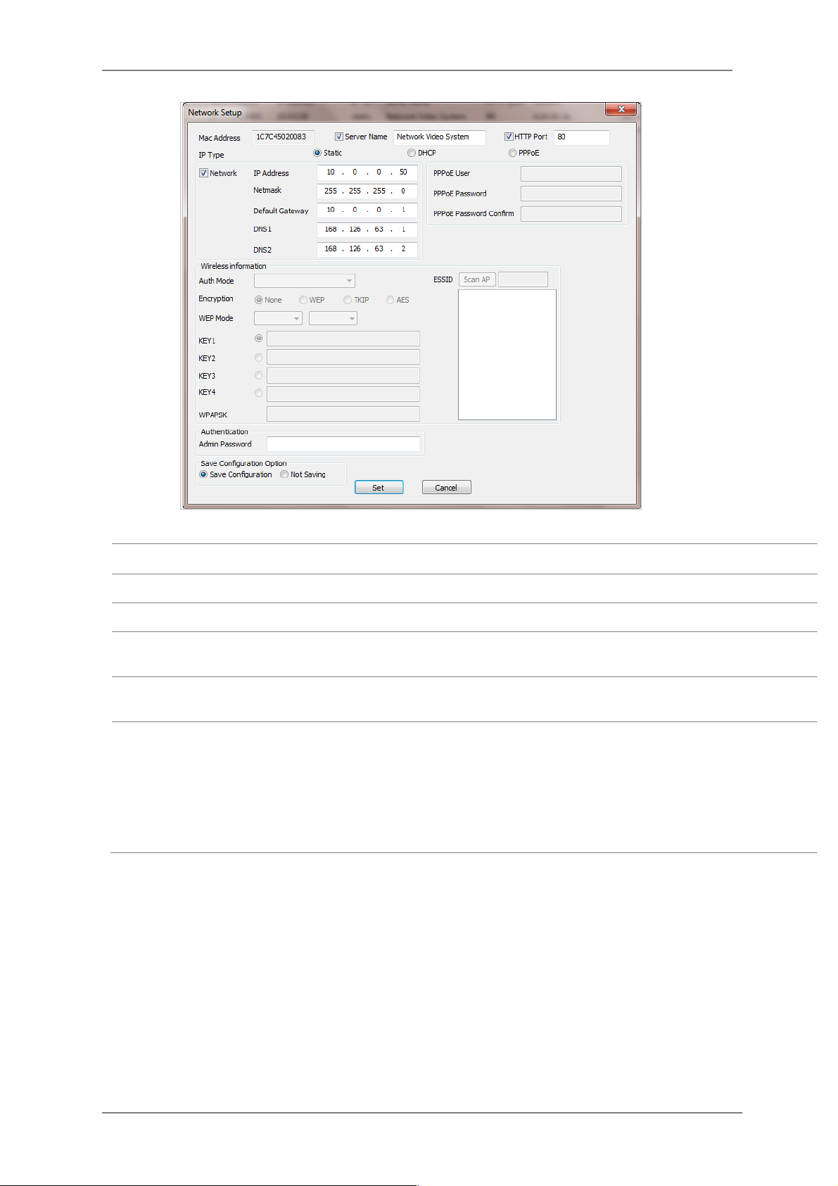
When one IP device is selected, the following screen will appear
MAC Address
MAC address of the selected device is shown.
Server Name
Input desired name of camera i.e. Lunch Room
HTTP Port
Input port number to access IP devices homepage via web. Default port is 80
IP Type
Select the type of address (Static / DHCP / PPPoE) Use STATIC for manual IP setup
Page 28
ENVI Series: VTC-IR402NZ
27
Network
General network parameters are required in this part. Please contact your network
administrator for detail.(IP Address, Netmask, Default Gateway, DNS1, DNS2)
Authentication
(Admin Password)
Password for the IP device.
(Default password for Vitek products is “root” unless already changed)
Save Configuration
Option
Select whether the configured contents is to be saved in the Camera memory or not.
• Save Configuration: Changed values will be saved in the Camera memory of the
device, which means the changes are permanent.
• Not Saving: Changed values will not be saved in the Camera memory, which
means if the IP device is turned off the changes are lost and the previous setting
will be applied back.
Click Set button to apply the changed values to IP device. If you don’t want it, click Cancel button.
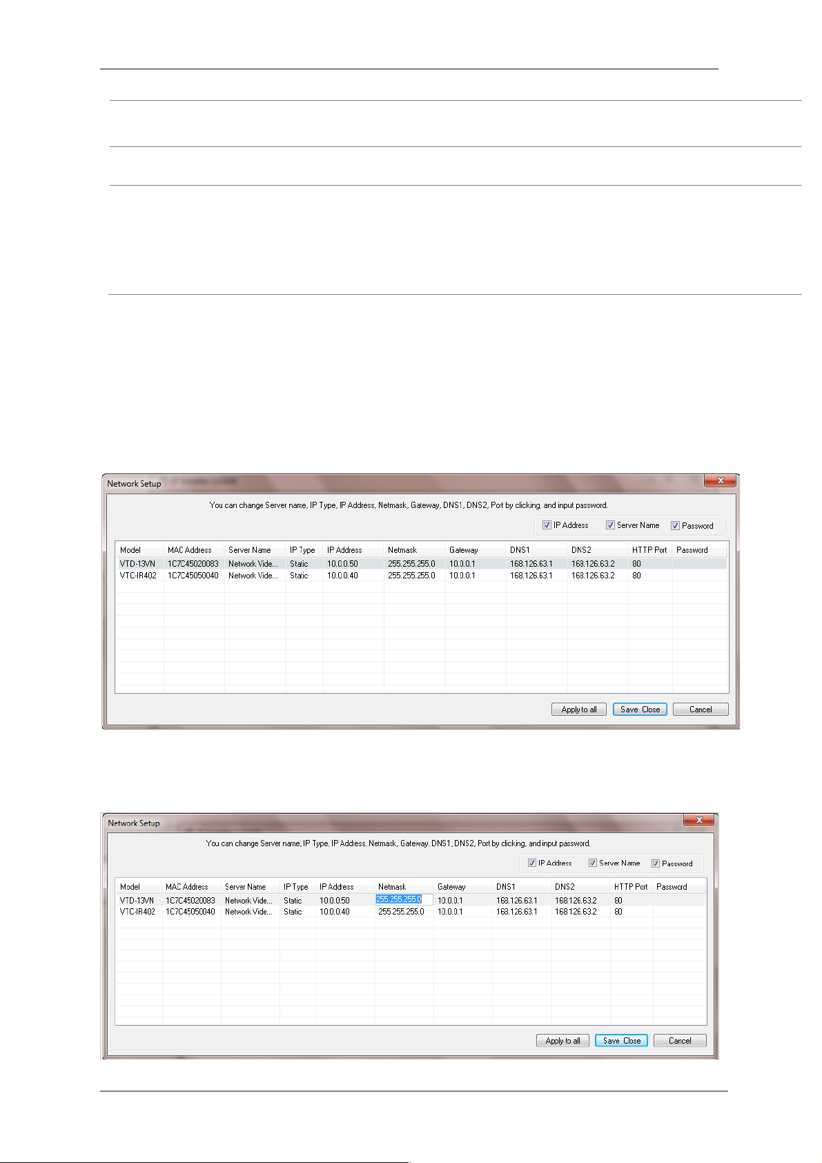
When two or more IP devices are selected
You can select two or more IP devices at the same time by clicking one after another while CTRL
key is pressed. The result is shown as below.
To configure the network parameters of those devices, click the right mouse button or click
Manual IP Setup icon on the main Toolbar with multiple IP devices selected as shown above.
Then the following window will show up.
You can modify the value of each changeable field by clicking it. The following shows an example
of entering a new value to a field.
Page 29
ENVI Series: VTC-IR402NZ
28
Model
Model Numbers of the IP devices that you selected.
MAC Address
MAC address of the selected device is shown.
Server Name
Name of the selected IP device.
IP Type
How to assign IP address to the device (Select Static here for Manual IP
Setup)
IP address, Netmask,
Gateway, DNS1, DNS2
General network parameters are required in this part. Please contact your
network administrator for detail.
HTTP Port
HTTP port number of the IP device for web access to homepage.
Password
Password for the IP device.(Default password for Vitek products is “root”)
If you click Apply to all button after changing just a field of one IP device, the remaining IP
devices will have the same value for that parameter. In this case, each device’s Server name and
IP Address field will have +1 incremented value added to the original value. For example, if the
first IP device has been given the server name of NetCam and Apply to all button is pressed, it
will be automatically changed to NetCam1 and the next IP device will have NetCam2 and so on.
The same applies to the IP address field.
For Password field, the entered information doesn’t increment but will use the same data.
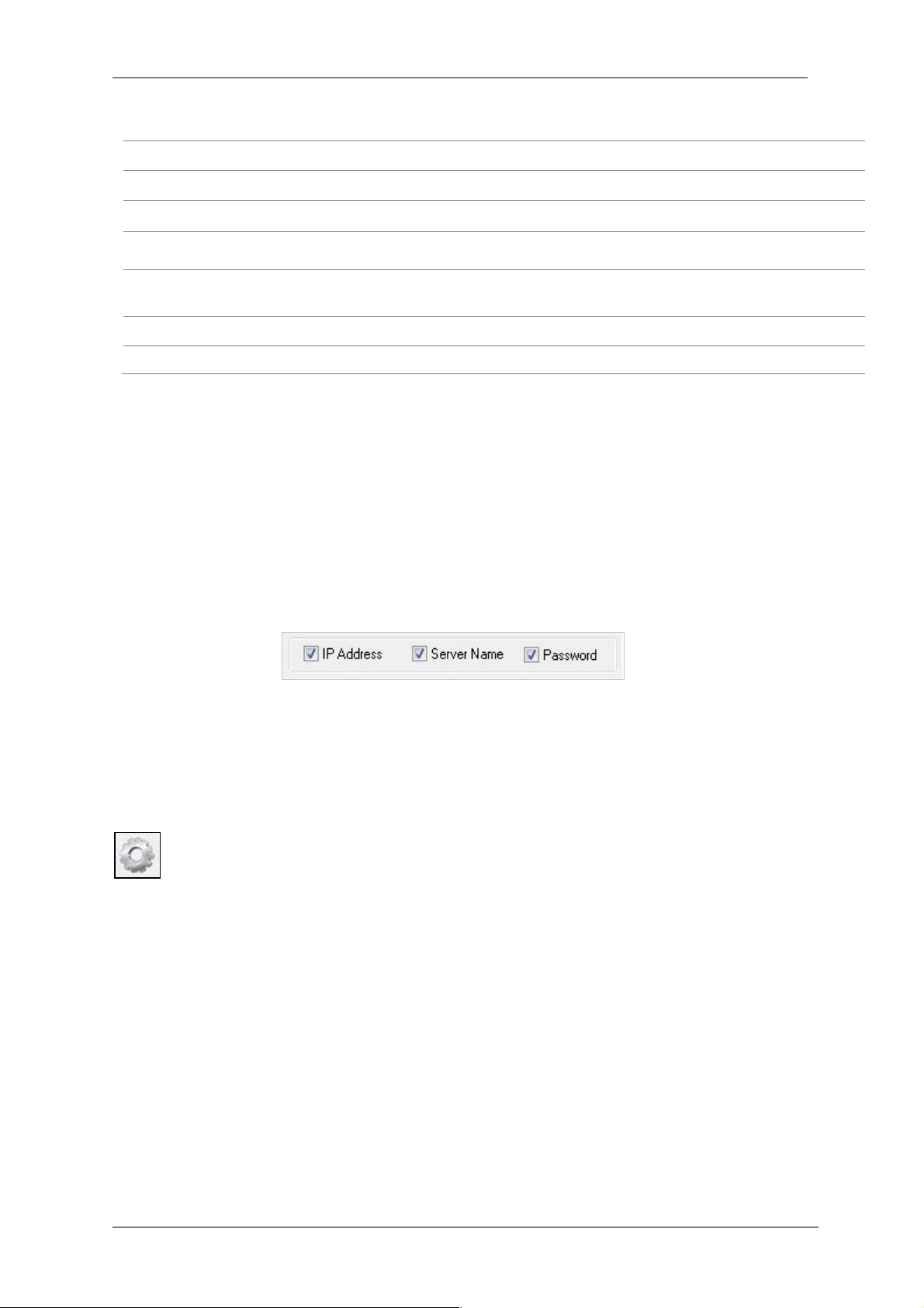
In using Apply to all, you can choose which field is affected. Put check marks only on the field
you want to use this automatic action as below.
Click Save & Close button to save the changed values in the camera memory of all the IP devices
and close the Network setup window.
11.3. Automatic Network Setup
Configuring the network parameters of the devices in the list can be started either by
clicking right mouse button or by clicking Automatic IP Setup button on the main
Toolbar. Before starting the setup, you first need to choose the one to be configured. In
this setup mode, IP Installer program checks your local network and assigns available IP addresses
to the IP devices. You have a choice of using those automatically assigned IP addresses, or you
can just enter other IP addresses as you desire.
Page 30
ENVI Series: VTC-IR402NZ
29
Server Name
Name of the selected IP device.
HTTP Port
HTTP port number of the IP device for web access to homepage.
IP Type
How to assign IP address to the device (Select Static here for Manual IP Setup)
Network
General network parameters are required in this part. Please contact your network
administrator for detail. (IP Address, Netmask, Default Gateway, DNS1, DNS2)
Authentication
(Admin Password)
Password for the IP device. (Default password for Vitek products is “root”)
Save Configuration
Option
Select whether the configured contents is to be saved in the Camera memory or not.
• Save Configuration: Changed values will be saved in the Camera memory of the
device, which means the changes are permanent.
• Not Saving: Changed values will not be saved in the Camera memory, which
means if the IP device is turned off the changes are lost and the previous setting
will be applied back.
Click Set button to apply the changed values to IP device. If you don’t want it, click Cancel button
to restore the previous values.
Page 31

ENVI Series: VTC-IR402NZ
30
11.4. Using DHCP Server
If your network has a DHCP server running for assigning IP addresses, you may choose to let it
assign IP addresses to the IP devices on the list. To do that, first open the Network Setup window
either by Manual IP Setup or Automatic IP Setup procedure. Choose DHCP in “IP Type”
selection, then IP Address, Netmask, Default Gateway field in Network setup area on the
window will be disabled to input as shown below.
Note: If your network has more than one IP address Zone at the same time, the
confirmation window will be displayed as below. You need to choose the one you
are going to use for your IP devices.
Page 32

ENVI Series: VTC-IR402NZ
31
For setting up other fields on the setup window, refer to Section 0 Manual Network Setup on
page 26. After filling the fields with appropriate values, click Set button to apply the changed
values to IP device. If you don’t want it, click Cancel button to restore the previous values.
11.5. Using PPPoE
If your network environment is based on PPPoE connection, you’ll need to choose PPPoE on IP
Type selection. First open the Network Setup window either by Manual IP Setup or Automatic
IP Setup procedure. Choose PPPoE in IP Type selection, and then all the fields in Network
setup area on the window will be disabled. The network settings such as IP Address, Netmask,
Default Gateway and DNS are no longer available to enter. You only need to enter the Server
Name, HTTP Port number, and login authentication for your PPPoE connection.
Page 33

ENVI Series: VTC-IR402NZ
32
MAC Address
MAC address of the selected device is shown.
Server Name
Name of the selected IP device.
HTTP Port
HTTP port number of the IP device for web access to homepage.
IP Type
How to assign IP address to the device (Select PPPoE in this mode)
PPPoE
User Authentication for PPPoE Connection.
• PPPoE User: Enter User ID.
• PPPoE Password: Enter Password for the User ID.
• PPPoE Password Confirm: Enter the same Password again.
Authentication
(Admin Password)
Password for the IP device.
(Default password for Vitek products is “root” unless already changed)
Save Configuration
Option
Select whether the configured contents is to be saved in the Camera memory or not.
• Save Configuration: Changed values will be saved in the Camera memory of the
device, which means the changes are permanent.
• Not Saving: Changed values will not be saved in the Camera memory, which
means if the IP device is turned off the changes are lost and the previous setting
will be applied back.
Note: After setting up the network for the IP devices, make sure the IP devices are
accessible on the network from your computer. It can be done by running Live
View function of the homepage of the IP device’s built-in server. Refer to
Section
11.8
Live View
on page 36
for more information.
Page 34

ENVI Series: VTC-IR402NZ
33
11.6. Updating Firmware
Once IP devices are searched and shown on the screen as functioning successfully, you can update
the firmware of them in “IP Installer” program. To do that, first check the firmware version of the
device, which you can find on the IP Installer window.
In the above picture, the firmware version of this product is 4.14-01-ds while the latest
firmware version available is 4.16-B0-ds-VI as you could see at Vitek’s homepage
(http://www.vitekcctv.com/Downloads.asp). If you decide to update the firmware, first
create a folder on your computer for the update firmware, than download the latest firmware to
that folder.
Then select the IP device to be updated on IP Installer window, then click Update Firmware
button from the toolbar. The following window will be displayed.
You may find the Password field is empty on the window shown above. If so, click the Password
field of the IP device and enter the proper password for the device. You are not allowed to update
the firmware if the correct password is not provided.
After the password is entered, the Start Update button will be enabled now. Click the button to
see the following window for selecting the folder where the file has been saved.
Highlight the
folder than click
OK.
Page 35

ENVI Series: VTC-IR402NZ
34
After clicking OK the following window will be displayed.
You can also select multiple IP devices at the same time, and have them start firmware updating in
a single step. Select the files to update by holding CTRL key and selecting which IP devices to
update
Click Start Update button. You will see the update window brought up with multiple IP devices
listed.
The rest of the procedure is the same as in the firmware update case for a single IP device.
Note: Do not CLOSE window until completed, to avoid permanent damage to the camera.
Page 36

ENVI Series: VTC-IR402NZ
35
11.7. Filter Configuration
When you need to search only for the IP device having a specific range of MAC or IP
addresses, you can do it by using this feature. To set the search condition, click Filter
Configuration button on the Toolbar, then the following window will show up on the
screen.
The first six HEX characters are already filled in with 1C:7C:45, which is the MAC prefix for Vitek
products. Put a checkmark in MAC Address or IP Range to set the range for searching.
You can set the range of IP addresses to scan as shown below. In this example, all the IP devices
having MAC address starting with 1C:7C:45 will be listed on the result window after scanning.
Or you can look for a single IP device having a specific IP address as below.
IP Address range for searching can be entered as follows.
You may even set both MAC Address and IP Range together at the same time.
After setting the searching range as explained above, click OK button. Then IP Installer program
window will show the searching range on the top right portion of the window as shown below.
Page 37

ENVI Series: VTC-IR402NZ
36
To start searching with this condition now, click Search Product button on the toolbar.
The program will start searching and show the result after a moment.
11.8. Live View
Once searching and configuration on IP devices are done, you should make sure that the IP
devices are accessible with the new settings. The best way to do it is by connecting to the
homepage of each IP device’s built-in server, and starting Live View feature.
Select Go Product Homepage when you click the right mouse button on the IP device to test.
If you select Go Product Homepage, the homepage of that device’s built-in server will
be opened on a new Web browser window as shown below. This is the same result when
you click Connect Product Homepage button from the Main Toolbar.
Page 38

ENVI Series: VTC-IR402NZ
37
Click Live View on the top right of the window, then ENVI Series Viewer ActiveX program will be
started. If you have not installed the ENVI Series Viewer program before, it will ask for a
confirmation to install it. Allow it and you will be able to find out whether the configuration by IP
Installer program is properly done.
Note: Refer to
Section 20.
ENVI Series Viewer
on page 90
for detailed information
about the ENVI Series Viewer ActiveX program.
Page 39

ENVI Series: VTC-IR402NZ
38
12. ENVI Admin Menu
After connecting to a VITEK ENVI Series camera via web browser, you’ll find the web page as
shown below. The upper rightmost item of the menu is Admin; this is where you can set up most
of the features in the VITEK camera you’re connected to.
12.1. Entering Admin Menu
Click Admin then you’ll see a login window. In the login window, enter root for both ID and
password as they are the factory defaults. Press Enter key or click OK.
Now the Admin Menu will be displayed as shown below. This will guide you to the top level menu
items, which are Quick, System, Network, Device, Advanced, Recording, and Utilities. Clicking any
of these top level menu items will display submenu items and brief descriptions.
Page 40

ENVI Series: VTC-IR402NZ
39
12.2. Admin Menu Structure
The following table shows the hierarchy of the Admin menu structure that we’re going to deal with
in this manual.
13. Quick Configuration
In Quick Configuration, you will be able to set up many of the essential parts of the configuration
in a simple manner without going into details. Selecting Quick Configuration gives you the menu as
seen below. You can perform each setup by clicking the one you would like to configure.
13.1. Step 1: Changing Server Name
Click Server Name on System Configuration menu, then Server Name Setup windows will be
displayed. Refer to Section 14.1 Server Name Setup on page 40 to see how to change the
server name.
13.2. Step 2: Time Setup
Click Date & Time on System Configuration menu, then the Local Date & Time Configuration
window will be displayed. Refer to Section 14.2 Date & Time on page 41 to see how to set
up.
13.3. Step 3: Network Setup
To make a connection to the Internet, it is required to figure out the type of the Internet service
you’re using. Refer to Section 15. Network Configuration on page 45 to see how to set up.
Page 41

ENVI Series: VTC-IR402NZ
40
13.4. Step 4: IPCCTVDNS.COM
When VITEK Server is used in a Dynamic IP environment, it is required to utilize
IPCCTVDNS.com feature. Refer to Section 37. IP-CCTV DNS Registration on page 151 for
setup information.
13.5. Step 5: Recording Configuration
Vitek cameras with MicroSD card can be configured for recording options in this section. Refer to
Section 18.1 SD / MicroSD Card Configuration on page 79 to see how to set up.
13.6. Finish
After clicking Finish all changes will be saved automatically to the camera/server
14. System Configuration Menu
When you click on System Configuration item on Admin Menu, the following sub menu will be
displayed.
14.1. Server Name Setup
Click Step 1 on Quick Configuration or Server Name under System Configuration then the
following will be displayed and you will find out the system information such as model number of
the VITEK camera, server name (camera name), MAC address (serial number), firmware version,
and Web image version.
Page 42

ENVI Series: VTC-IR402NZ
41
As an administrator, you can change the name of the camera/ server, but other values are not
allowed to be changed. To change the camera/ server name, enter a new name in the Server
Name field. You may use up to 21 alphanumeric or up to 10 Unicode characters. Tab or any other
special characters are not allowed. Click Apply button to save the setting and it will take effect
immediately.
14.2. Date & Time
Click Step 2 on Quick Configuration. Or Date & Time under System Configuration Fill the
Date and Time fields with your local time and date information. If you're in a different time zone,
put a checkmark on Change Time Zone, then select the correct region from the dropdown list to
make the time zone change, you need to click Apply button and reboot the system.
If you want to retrieve the exact current time from a NTP server on the network, click Get NTP
Server Time button. Clicking Refresh button will display the date and time retrieved from the
camera. Then click Apply button to save it.
Note: In order to retrieve Time and Date information from a NTP server, you need to put
NTP server address in advance of setting up, such as pool.ntp.org.
Page 43

ENVI Series: VTC-IR402NZ
42
14.3. Admin Password
To change the password for the administrator, click Admin Password in System Configuration
menu.
Default ID for admin account is fixed as “root” and is not allowed to change. In Old Password
field, enter the current password. In both New Password and Confirm Password fields, enter
the same new password. The password must be between 4 and 23 alphanumeric characters. Click
Apply button to put it into effect.
Because you have replaced the password with a new one, the existing network connection made
with old password to VITEK camera is lost now. You will have to reconnect to the VITEK camera
using new password.
14.4. Access Control
Click Access Control on System Configuration menu. The following windows will be displayed.
From the Access Permission window, select either one you would like to use. Click Apply button
to save the change.
• Full Access: Any user can access the camera/server and use all the features without limits.
• Limited Access: Only registered users can access the camera/server and have limited
privileges.
•
14.5. User Registration
You can add, modify, or delete users for your VITEK camera/server here. Once registered as
Limited Access setting, the user can access the VITEK camera/server with some limited privileges.
14.5.1. Add
To add a user, click User Registration on System Configuration menu. When Add is selected,
you can add users and define their passwords, names, and access permission levels respectively.
Page 44

ENVI Series: VTC-IR402NZ
43
Enter a User ID between 4 and 23 alphanumeric characters. In both Password and Confirm
Password fields, enter the identical password respectively. The password must be between 4 and
23 alphanumeric characters. In Name filed, enter the user’s name up to 23 alphanumeric
characters.
Now select one of the four items from System Resource Access Permission, which defines the
permission level for registered users to the VITEK camera.
• All Channels Access: User can use all the features except for Configuration in Admin Page.
• General Access (only live viewing access): User can only use Live View feature.
• No Access: User is not permitted any of the features.
• Selective Access: User is allowed to use only the selected features. With this item selected,
you can now configure the details under this menu for the user.
VITEK cameras may have multiple VS Modules registered in it. When you click on any of the
Enable check boxes, other fields in that row are now enabled to select.
• VS Module ID: VS Module is a network device that has been registered in the VITEK camera
• Camera No.: Among the cameras of the VS Module select one to set up. (between all,1or2)
• Alarm Control: Determine if Alarm control is to be allowed.
(selected models)
Page 45

ENVI Series: VTC-IR402NZ
44
• Audio Control: Determine if Audio Control is to be allowed. (
selected models)
After finishing the registration process, click Apply button to add the user.
14.5.2. Edit
To edit a user account, select Edit. In this part, you can modify the existing user’s name,
password, and access permission. User ID is not allowed to change. Once selecting a user ID to
edit, the procedure is the same as in Add section.
To see existing users, click Select UserId, and select a user to be edited from the dropdown box.
Then you can change the password, name, or access permission, and click Apply button to save
the setting. Setup of Access Permission can be done the same way as in the Add section.
14.5.3. Delete
To delete an existing user, select Delete.
From the list of the users, select a user to delete. Click Delete button to confirm the deletion.
Page 46

ENVI Series: VTC-IR402NZ
45
15. Network Configuration
Configuring the network is dependent on how an IP address is assigned in Ethernet-based
environment, which is static IP, dynamic IP (DHCP), or PPPoE.
15.1. Static IP Configuration
Select Network Configuration under Network configuration
For static IP, select Static IP and input IP address, NetMask, Gateway, DNS1, DNS2 and click
apply to save settings. After apply, program will ask to close web browser for updates, which will
take 20~30 seconds. If Back button is clicked all values will be discarded. If Refresh button is
clicked, the program will load previous values.
Page 47

ENVI Series: VTC-IR402NZ
46
15.2. DHCP Client Configuration
To use DHCP a DHCP server must exist in the network environment. Select DHCP Client from
Network Configuration, click Apply. And all information needed will be filled in automatically
15.3. PPPoE Configuration
PPPoE is used to connect VITEK products to a PPPoE modem provided by the ISP. Since PPPoE
needs verification, ID and a password are necessary to access the network. Type in PPPoE user ID
and password
Page 48

ENVI Series: VTC-IR402NZ
47
15.4. Network Ports
In this configuration, you set up the HTTP port for VITEK cameras to communicate with the Client
PC. HTTP Port is the network port that is used when a Client PC connects to the VITEK camera
Web page. It can be assigned between 80 and 65535.The default value is 80.
15.5. Bandwidth Control Configuration
Bandwidth control is for limiting maximum network traffic. If it is enabled with Bandwidth limits,
maximum data size transferred from VITEK cameras won’t exceed bandwidth limits set by users. If
transferred data is exceeded, part of the data will be randomly lost.
If multiple users try to access a VITEK camera when bandwidth control is enabled, users
connected to the VITEK camera will share network bandwidth limit.
Note: If the HTTP port number is changed to a different value than default (80), make
sure the new HTTP port number goes together with the VITEK cameras IP address.
For example, when a VITEK cameras IP address is 192.168.1.100 and the HTTP
port is 8080, you will have to enter http://192.168.1.100:8080 to connect to the
camera.
Page 49

ENVI Series: VTC-IR402NZ
48
15.6. View Network Status
This menu shows network status of VITEK cameras.
15.7. Network Status Notify
This feature helps to send updated network status information to registered email address if any
changes happen. This function will work under DHCP or PPPoE.
If Network Status Notify is set to Enable, VITEK cameras network status will be emailed to a
specific person in case of the following events:
• When it is set to Dynamic IP in the Network Configuration menu, and the VITEK camera has
been given a new dynamic IP address and connects to the network.
Or,
• When it is set to PPP Client on WAN-Modem menu, and the VITEK camera has been connected
to the network with ISP or PPP server.
To configure, click Network Status Notify on Network Configuration menu. The following
window will be shown.
Note: This bandwidth control feature works well in M-JPEG video transmission. But, for
H.264, dropping data packets may cause low quality of video, so it is
recommended to utilize CBR and frame rate control instead of bandwidth control
for H.264 video. Refer to
Section 16.2
Camera & Motion
on page 55
for
more info on CBR and Frame rate.
Note: Network Bandwidth control is managed by the VITEK camera and it drops any data
packets if required, thus you may experience slow connection when this feature
is enabled.
Page 50

ENVI Series: VTC-IR402NZ
49
First, select Enable to use the feature. Then enter the address of the SMTP server which is
needed for email service. If your SMTP server requires a user ID and a password for authentication,
you will have to Enable Authentication Login and enter the user ID and Password.
In Sender field, enter your email address or other meaningful words that will show the message
was sent from the VITEK camera as a notification. Now enter the email addresses of the recipients
in the Recipient fields, up to 3 addresses. In the User-Defined Message box, you may enter a
message to explain why the message was sent. After finishing the setup, click Apply to save
settings.
Mail Notification
Enable: Send email
Disable: Do not send email
SMTP Server
SMTP Server address for email service
Authentication Login
Enable: user ID and password are required for SMTP
server
Disable: user ID and password are not required
User ID
User ID for SMTP server
Password
Password for SMTP server
Sender
Email address of Sender or Name
1st / 2nd / 3rd Recipient
Email Addresses of the Recipients (up to 3 addresses)
User Defined Message
Message to be included in the Notification email
Page 51

ENVI Series: VTC-IR402NZ
50
15.8. IP-CCTV DNS Setup
Note: Refer to Section 37. IP-CCTV DNS Registration on page 149 for further details on
configuration.
IP-CCTV DNS service provides a static & public domain name to help user’s access VITEK cameras
even though their IP address has changed or they are used in a local network. For proper function
of IP-CCTV DNS service, products need to be accessible through the internet.
15.9. Port Forwarding & UPnP
UPnP(Universal Plug and Play)is a kind of network protocol to help users to find and configure
network products in the same local network area. Port forwarding is to assign a certain network
port to a network product so users can access it from outside of the Local Area Network. Generally,
port forwarding can be configured from the network router.
UPnP port forwarding is made up with finding an available network port, assigning it to a VITEK
camera and reporting overall network configuration of a VITEK camera to IP-CCTV DNS server.
Users have to register products into IPCCTVDNS server and IP-CCTV DNS service should be
enabled.
There are 3 options in UPnP Port Forwarding.
• Manual: User Assigned Port issued when users can access network router (hub) and
manually assign available network ports to VITEK cameras. In this case, users have to type
already-assigned network ports under User Assigned port.
• UPnP: User Assigned Port is used when users want VITEK cameras to configure port
forwarding of network hub with user-assigned network port. If it fails, try to change userassigned port
• UPnP: Auto Selected Port is used to let VITEK cameras deal with all network configurations
automatically.
Please note that the network router needs to support UPnP Port Forwarding. There is a limit for the
maximum number of UPnP devices. If it is properly configured, results will be displayed under
UPnP status.
Page 52

ENVI Series: VTC-IR402NZ
51
3
15.10. RTP/RTSP Setup
Factory default is Enable to be used with other manufactures VMS software’s
RTSP (Real-Time Streaming Protocol) is a protocol to transfer video and audio streams over the
network. Any application supporting Standard RTSP can be used for VITEK cameras. Quick Time
Player or VLC program can be used with this; it may not be supported in the environment within a
firewall. There are two types of usage; one for Unicast address condition and the other for
Multicast address condition.
For Unicast Address:
Use “rtsp://network video server ip address/cam0_0”. If there are multiple channels, use
cam0_x, x (0~3) with each number applied. If there are multiple modules, use camx_0 x (0 ~ 3)
with each module number applied.
For Multicast Address:
Use “rtsp://network video server ip address/mcam0_0”. If there are multiple channels, use
mcam0_x, x (0~3) with each channel number applied. If there are multiple modules, use mcamx_0
x (0 ~ 3) with each module number applied.
Page 53

ENVI Series: VTC-IR402NZ
52
Service
Enable: Start RTSP service
Disable: Stop RTSP service
RTSP Port
In normal case, use default port number 554 to connect to RTSP service.
If not using port 554, enter the port number you want to use.
e.g.) port number 445==>rtsp:// network video server ip
address:445/cam0_0
RTP Start Port
The starting number of the port for video transfer. Each time video
transfer connection is made, the port number also increases.
Multicast
Address
Address for multicast video transfer.
The multicast address 0.0.0.0 is for stopping multicast.
Multicast Port
Port number for viewing the video with a multicast address
16. Device Configuration
16.1. Privacy Zone
Users can set a privacy zone if a certain part of the screen needs to be unmonitored.
To set the region, click Privacy Zone from Device Configuration category.
Page 54

ENVI Series: VTC-IR402NZ
53
To Add a Privacy zone click New button, a Green-colored box will appear, click on the Green box
and it will turn Red, at this point you can resize it by clicking and holding any corner and drag to
desired size. To relocate box click and hold anywhere inside the box and drag to desired location.
Click Apply when done
Page 55

ENVI Series: VTC-IR402NZ
54
Users can add up to 8 Privacy Zones per screen by repeating above steps. If you add more than 8,
an error message will display on the screen.
To delete a privacy zone, click the zone and click Delete button followed by Apply button.
Page 56

ENVI Series: VTC-IR402NZ
55
16.2. Camera & Motion
This menu is used to set up the selection of video format, data added to video data, encoding
speed, audio control, image resolution, video quality, motion detection, etc.
Click Camera & Motion on Device Configuration menu. The configuration menu will be
displayed, and it may be different between VITEK cameras.
• M-JPEG: This format requires much higher network bandwidth than H.264 compression. But
because of its higher quality of still image, it is adequate for detailed reviewing of stored video.
• H.264: In this format, each frame data is related to other nearby frames. For this reason, it
provides much higher compression ratio than M-JPEG and is adequate for video transfer.
However, if network conditions are limited dropped frames in video data is possible, the video
quality can be relatively low. With VITEK Cameras, you can set the number of P-frames in the
video which is independent still images between I-frames.
•
You can configure the video data format and other information to be contained in it.
Note: For Dual Stream products, most of the parameters are dependent on primary
stream value.
Page 57

ENVI Series: VTC-IR402NZ
56
• Video with Flexible Extra System data: If Enabled, video data will contain UART sensor
data from COM port. .(Feature'not'available'on'this'model)
• Video with user defined message: If Enabled, video data will contain the user-defined
data. (Reserved Field) .(Feature'not'available'on'this'model)
• Video with PPP status: If Enabled, video data will contain PPP connection status. .(Feature'
not'available'on'this'model)
• Video with camera name: If Enabled, video data will contain the camera name. .(Feature'not'
available'on'this'model)
• Video with server name: If Enabled, video data will contain the server name that you
defined. .(Feature'not'available'on'this'model)
• Video with IP address: If Enabled, video data will contain the IP address of the video
server. .(Feature'not'available'on'this'model)
• Audio: (not available on all models) Select if Audio function is to be used (applies to Primary
Stream only). VITEK Cameras provides 2-way audio streaming by combining microphone input
with video data. Users can listen to the streamed audio through a PC and speakers.
• Frame Rate: For Primary Stream, this is the number of frames compressed in every second.
You can control the network traffic with this parameter. For Secondary Stream, it can be set to a
manner of 1/2, 1/4, 1/8... of the primary stream.
• Image Size: Select the resolution of each channel’s video
• Encoding Standard: Select the compression method of each video, either M-JPEG or H.264
format. It is not allowed to set both channels to M-JPEG.
Below is the table of images sizes. To save the setting, click Apply button
Page 58

ENVI Series: VTC-IR402NZ
57
Video Format
SXGA
D1
CIF
QCIF
NTSC
-
704 x 480
352 x 240
160 x 112
PAL - 704 x 576
352 x 288
160 x 144
VGA
-
640 x 480
320 x 240
160 x 112
1.3M Pixel
1280 x 1024
640 x 480
320 x 240
160 x 112
2.0M Pixel
1920 x 1080
640 x 480
320 x 240
160 x 112
16.3. Camera Configuration
On the lower part of Camera & Motion Configuration menu, select a channel to configure.
In the example shown below, Primary Stream is set to H.264 for compression format. Enter
detailed parameters of the camera selected here.
Primary Stream of (H.264)
• Camera Name: Enter the name of the channel up to 21 alphanumeric or up to 10 Unicode
characters.
Page 59

ENVI Series: VTC-IR402NZ
58
16.3.1. Rate Control Mode
H.264
Rate Control Mode: VBR (Variable Bit Rate)
Video frames are encoded with selected
image quality and GOP. Encoded frames have
different data size from each other.
Image Quality: one of 6 quality levels
(Low Compression / Highest /High
Normal / Low / Lowest)
GOP Structure: Distance between IFrames. That is filled with P-frames.
Rate Control Mode: CBR (Constant Bit
Rate)
Video frames are encoded with selected
image quality and GOP. Encoded frames have
the same data size as other frames. Due to
the constant bit rate, it has better stable
transmission performance.
Bit Rate Control: Total number of Bits
encoded per second. The higher Bit
Rate, the better image quality. Can be
set between 32kbps and 2Mbps.
GOP: Distance between I-Frames. That
is filled with P-frames.
M-JPEG
-
Image Quality: one of 6 quality levels
(Low Compression / Highest / High
Normal / Low / Lowest)
Page 60

ENVI Series: VTC-IR402NZ
59
16.3.2. Image Quality Setup
In Image Quality level setup, select “Low Compression” for higher image quality, but it requires
higher network bandwidth. Selecting the “Lowest” requires lower network bandwidth, but gives
decreased image quality.
After configuration is finished, click Apply button to save the setting. If you click Default button,
the entire configuration will be reset to the original values.
Motion Detection
• Motion Detection: (this is only available in Primary Stream) If enabled, Motion Detection
feature is activated and user can configure the areas where motion detection function will work.
Click Check All button for whole scene to be active (grid will turn Green) then click on any box
inside scene to take out that area from Motion Detection (box will turn Red) then click Apply to
save.
• Motion Sensitivity: Set the sensitivity of motion defined in Motion Detection Area. Select
between -100 and 100. 100 is the most sensitive.
After all the settings are done, click Apply button to save it. If Default button is clicked, all the
fields return back to original value.
Page 61

ENVI Series: VTC-IR402NZ
60
16.4. Accessing the camera setup menu
Camera SETUP menu can be accessed in two ways via web viewer.
Most frequent controls are available with the parameters directly in the below
table. More complicated settings such as PRIVACY, POINTING ZOOM & SMART
MOTION settings are available via ‘ADVANCED CAMERA MENU’ by activating
the camera OSD menu.
Page 62

ENVI Series: VTC-IR402NZ
61
16.5. Direct Control menu
SPECIAL
DEFAULT
DESCRIPTION
TV SYSTEM
Selects HDTV standards for US(60HZ) or EU(50HZ).
By this selection, 2nd analog video output switches to NTSC or
PAL accordingly.
D-ZOOM(Digital zoom) is available up to 32x.
D-ZOOM starts working when the optical zoom reaches its
maximum tele-position. Zoom ratio is displayed on the right bottom
corner of the monitor if DISPLAY ZOOM RATIO is set to ON.
US
or
EU
FOCUS
MODE
ZOOM
PUSH
D-ZOOM
OFF
EXPOSURE
MODE
AUTO
.
BRIGHTNESS
10 Adjusts the brightness of video(0~20).
SENS-UP AUTO
SENS-UP is the maximum integrations of frame by DSS(Digital
Slow Shutter) in low light.
Can set EXPOSURE MODE to AUTO, IRIS Priority, SHUT.
Priority, MANUAL and Flickerless
AUTO – Optimizes the video level by controlling the iris and the
shutter speed automatically.
IRIS Priority – Select to fix IRIS in a certain aperture and the
video level is controlled by an automatic shutter control. IRIS
Level menu is activated when EXPOSURE MODE is set to IRIS
Priority. Lower IRIS LEVEL will close the iris more and increase
the
field of depth in the daytime but significantly decrease the low
light performance. To Low of the IRIS LEVEL will result in foggy
video by the diffusion from the lens iris.
SHUT. Priority - Selects to fix SHUTTER speed at a certain
speed and the video level is controlled by an automatic iris
control. This mode is useful when color rolling occurs under
fluorescent lighting. It is not recommendable for outdoor in the
daytime.
MANUAL – Iris and Shutter can be set to a fixed value.
Flickerless – Reduces the flicker in video when US(60Hz) / EU
(50Hz) mode is used in 50Hz/60Hz fluorescent lighting respectively.
SHUT. Priority, MANUAL and Flickerless modes disable
SENS-UP and MOTION BLUR functions.
Page 63

ENVI Series: VTC-IR402NZ
62
SENS-U UTO
WD
WDR
Weight
OFF
WDR level can be selected from LOW, MID and HIGH.
Care should be taken to select this mode because video may
BLC
(Back Light
Compensation)
OFF
MID
DAY / NIGHT
EXT
for
IR LED
type
AUTO
for
Non IR
type
DAY
for
Non TDN
type
EXT — DAY or NIGHT is determined by the built-in light photo
sensor. Camera with IR LED must be set to EXT.
AUTO — Used when DAY or NIGHT is determined by light level
through the lens and DA
Y
from/to NIGHT is switched automatically
by the scene brightness.
When EXPOSURE>AGC is less than 12, DAY/NIGHT AUTO is
disabled and forcibly switches to _(DAY) to avoid malfunction.
EXT, B/W(NIGHT) and COLOR(DAY) is independent on AGC
level. When EXTERNAL
IR LED is used with NON IR LED model
,
please set to IR LED MODE ON.
B/W(NIGHT) — Forcibly removes IR cut filter and switches to
B/W regardless of light level.
COLOR(DAY) — Forcibly D
AY
/NIGHT is disabled and outputs
color video.
OF
F
A
P
R
AUTO – SENS-UP is enabled or disabled automatically by
the scene brightness.
OFF – Disables SENS-UP
Improves the visibility for bright areas and dark areas by
double capture of image with LONG and SHORT exposures.
With WDR ON, the frame rate becomes half by double
capture.
CVBS video signal - Connecting 2nd video to CVBS port
disables WDR function temporary. It should be considered
when installer adjusts the video with installation monitor via
CVBS video signal
ON – Improves the visibility of dark objects caused by bright
back light. Outside area of BLC window can be over saturated.
Able to set BLC POSITION in ADVANCED CAMERA
MENU>BLC POSITION
HLC – Cuts out the highlight area with black mask and excludes it from compensation. The more sensitive it is to bright
light. HLC LEVEL is adjustable in ADVANCED CAMERA
MENU>HLC LEVEL
lose its quality in some environments by the over compensation.
※
3D-NR
3D-NR is a very sophisticated and powerful time-based noise
reduction technology by monitoring the noise for the several
video frames and defining and eliminating them consecutively at low light. Higher setting reduces noise much more but
results in losing the sharpness and tail effects or motion blur
may occur.
Page 64

ENVI Series: VTC-IR402NZ
63
Day & Night
Threshold
HIGH
AGC1 2
10
WHITE BAL
WB Manual
R-Gain/
B-Gain
ATW
AGC amplifies the video gain for brighter video but noise and
AGC level less than 10 disables AUTO in DAY/NIGHT
Activates when WHITE BALANCE is set to MANUAL.
Adjustable 0~20.
SHARPNESS
10
MIRROR /
FLIP
Reverses the video left and right and/or up and down by
MIRROR/FLIP.
No Mirror, No Flip : Normal display without mirroring or flipping
No Mirror, Flip : Video is reversed upside down.
Mirror, No Flip Ver. : Video is reversed left and right.
Mirror, Flip HV : Video is reversed left and right and upside down.
When the video is reversed by Ver. or HV, then the joystick
directions are reversed accordingly. This feature is very useful
when a camera is installed in upside down.
NO
DEFOG
Weight
MID
LEVEL — LOW, MID, HIGH
Video quality can be less in normal environments.
Adjusts the sharpness of video.
COLOR GAIN
10 Adjusts the color level of video.
GAMMA0 .5 Adjusts the gamma of video.
D<-->N Threshold is a threshold level and Gap to switch from
DAY to NIGHT.
Low makes the camera enter night mode at a lower light level.
High makes the camera exit the night mode at a higher light
level.
white pixel will increase.
ATW, ONE PUSH and MANUAL are available for the white
balance modes.
ATW – White balance is continuously working when the
color temperature changes in the range of 2,000K~8,500K.
ONE PUSH – White balance works only when ONE PUSH
is selected.
MANUAL – This mode can be used only when the color
temperature does not vary. White balance is fixed to the
settings of R_GAIN and B-GAIN
AUTO : Enhances foggy video automatically according to
status of scene
MANUAL : Sets to enhance foggy video manually regardless
of status of scene
DEFOG OFF
Page 65

ENVI Series: VTC-IR402NZ
64
DISPLAY
Zoom Ratio
OFF
ON enables to display the Zoom Ratio on the bottom right
corner. OZx.x appears during the optical zoom and DZx.x will
display by multiplying the optical zoom ratio and the actual digital
zoom ratio.
DISPLAY ID
OFF
OFF
ON enables to display Camera ID on Monitor.
DISPLAY FOCUS
INDICATOR
ON
ON enables to display the Focus Indicator on Monitor
ON enables to display Camera Tittle on Monitor.
DISPLAY Tittle
OFF
IR LED Control(AUTO/OFF) is available with IR LED model only.
If IR LED is set to OFF, IR LED will be turned OFF but DAY or
NIGHT is still determined by the built-in light photo sensor.
IR LED Mode is workable with IR LED built-in model only.
IR LED
MODE
LENS
INITIALIZE
Lens initialization is necessary during the installation or the
regular operation to align the position data with the mechanical
positions whose lens elements may move and deviate from its
calibrated position by shock or vibration, for example, during
transportation.
LENS INIT checks the positions for zoom and focus at both of
the end positions and saves them for the references.
Lens initialization is automatically executed at power up.
[ CAUTION ]
It is strongly necessary to execute LENS INIT in cases below;
1) At the final step for the installation.
2) When focus becomes out of control by shock or vibration
Page 66

ENVI Series: VTC-IR402NZ
65
16.6. Advanced Camera OSD menu
Click ‘ADVANCED CAMERA MENU’ bar in CAMERA CONTROL menu to activate
the camera OSD menu.
Click Up/Down/Left/Right bars to navigate or change the parameters.
These options have been pre-configured at the factory for optimal performance.
1. PRIVACY (default: OFF)
10 Privacy zones which can be enabled individually by ZONE DISP are available to
mask areas of the video.
• ZONE NUMBER – Set a number to select a privacy zone from 1~10.
• ZONE DISP – ON enables a relevant privacy zone.
• H-POS, V-POS, H-SIZE and V-SIZE – Adjust the size and position of zone.
• COLOR – Select the color used for masking the zone form eight colors.
• TRANSPARENCY – Defines the transparency for the mask zone.
2. MOTION (default: OFF)
MOTION can detect the movement in the motion window and displays the results
in blocks and/or a text message
• SENSITIVITY – Adjusts the detection sensitivity for motion. Higher value increases
the sensitivity to detect small motion easier. Too high of sensitivity will cause the
erratic detection by tree leaves or light level changes and too low setting
will fail in detecting motion.
• H-POS,V-POS, H-SIZE,V-SIZE - Adjust the size and position of the detection
window
• BLOCK DISP – ON enables to display the blocks for the detected area.
• MOTION OSD – ON enables to display a text message, MOVING !!!
• SMART MOTION ZOOM– ON enables to Automatic Zoom IN/OUT when motion
is detected and also enables MOTION OSD to ON.
MENU V3 .12
1. PRIVACY
2. MOTION
3. TITLE SET
4. SMART IR
5. MOTION DEBLUR
6. HLC LEVEL
7. BLC POSITION
8. POINTING ZOOM
9. EXIT
OFF
|::::::::::::::| 0
10
ON
SET
|:::::::|:::
:::|
SAVE&EXIT
Page 67

ENVI Series: VTC-IR402NZ
66
Area to be zoomed in by SMART MOTION ZOOM can be set in MOTION> SMART
MOTION ZOOM>ZOOM TARGET. Clicking Up/ Down/ Left/ Right or Enter bars
for ZOOM TARGET varies the viewing angle to be zoomed when motion occurs.
Set the video left and right and/or up and down by MIRROR/FLIP.
(See description of “SMART MOTION ZOOM” for more details)
• STAY ZOOMING – Sets the duration time for zooming by Motion.
Set the direction of video by MIRROR/FLIP before SMART MOTION ZOOM setting.
Otherwise the zoom target could be different from your intention.
3. TITLE SET
Camera title (name) can be set and editable up to 15 alpha numeric and symbolic
characters from ASCII codes (ENGLISH only).
Clicking the Up/ Down/ Left/ Right bars to move the cursor for choosing characters
and click the Enter bar to select them. The selected characters are added and
displayed on the top left corner and the cursor moves right automatically for next
input.
• SP - Space is inserted when clicked
• BS - Cursor moves back when clicked
• CLR - Clears all the characters on input line when clicked
• POS - Sets the title position by using four direction bars and enter bar.
4. SMART IR (default: 0)
SMART IR can be set to reduce the saturation of strong IR illumination at
night in any menu of EXT, AUTO and B/W(NIGHT). Setting SMART IR in any
menu is identically applied to other menus. Zero(0) turns off SMART IR and High
setting avoids saturation but the corners will be darker accordingly.
5. Motion Deblur (default: 10)
ON enables MOTION DEBLUR to reduce the motion blur in certain indoor
environments. Noise or color rolling can increase..
CAUTION
: SMART MOTION ZOOM does not work in low light and B/W mode.
NOTICE
Page 68

ENVI Series: VTC-IR402NZ
67
6. HLC LEVEL (default: 10)
Cuts out the highlight area with black mask and excludes it from compensation.
Lower HLC LEVEL the more sensitive it is to bright light.
7. BLC POSITION (default: 10)
Improves the visibility of dark objects caused by bright back light.
Outside area of BLC window can over saturate.
BLC has a target window for compensation and its size and position can be set
by H-POS, V-POS, H-SIZE and V-SIZE.
8. POINTING ZOOM (default: ON)
ON enables to set off-centered location to be the center of zoom H-POINTER,
V-POINTER- Able to set the location of zoom center D-Zoom is available to
~ 32x
9. EXIT
SAVE & EXIT – Exits the menu after saving the parameters.
16.7. SMART MOTION ZOOM (Detail Function Description)
SMART MOTION ZOOM enlarges the area defined by a yellow window to a full size image when
motion is detected in the black window.
SMART MOTION ZOOM window can be re-sized by adjusting D-ZOOM RATIO
and moved by H-POINTER and V-POINTER.
UNLIKE the conventional zoom, which can zoom in/out the center area of image only, the flexible
zoom location and area, SMART MOTION ZOOM differentiates its usefulness from others.
That is, a conventional camera installed in the corner of the ceiling can zoom the center of the
floor in a room and result in losing the image of door on the sidewall. However, SMART MOTION
ZOOM can be set to see the door side and zoom in that area without missing the IMPORTANT
security point.
SMART MOTION ZOOM
H-POINTER
V-POINTER
O-ZOOM RATIO
D-ZOOM RATIO
MOTION CHK COUNT
RETURN
10
10
OX2.0
DX1.5
2
RET
Page 69

ENVI Series: VTC-IR402NZ
68
• H-POINTER (10): Moves MOTION ZOOM area (Yellow window) horizontally.
• V-POINTER (10): Moves MOTION ZOOM area (Yellow window) vertically.
• D-ZOOM RATIO (MZ2.0): Sets the area size to be Digitally zoomed when
motion occurs in the black window.
• MOTION CHK COUNT (2) - SMART MOTION ZOOM is activated after the
motion in MOTION CHK COUNT are detected in a certain period.
For example, "SMART MOTION ZOOM is activated after set # of triggers by motion".
16.8. POINTING ZOOM (Detail Function Description)
This camera has a very useful and powerful feature, POINTING ZOOM which can zoom
in/out any area.
POINTING ZOOM enlarges the area defined by a Yellow window to a full size image when
motion is detected in the black window.
POINTING ZOOM window can be re-sized by adjusting D-ZOOM RATIO
and moved by H-POINTER and V-POINTER.
UNLIKE the conventional zoom, which can zoom in/out the center area of image only, the flexible
zoom location and area, POINTING ZOOM differentiates its usefulness from others.
That is, a conventional camera installed in the corner of the ceiling can zoom the center of the
floor in a room and result in losing the image of door on the sidewall. However, POINTING
ZOOM can be set to see the door side and zoom in that area without missing the IMPORTANT
security point.
Set D-Zoom Pointer
POINTING ZOOM
H-POINTER
V-POINTER
RETURN
OFF
10
10
RET
s0/).4).'://-(OFF) - ON enables to set off-centered location to be the
center of zoom
s(0/).4%2 (10) - Sets the horizontal location of area to be zoomed by
0/).4).'://-
s60/).4%2 - Sets the vertical location of area to be zoomed by
0/).4).'://-
Page 70

ENVI Series: VTC-IR402NZ
69
EXAMPLE OF SMART MOTION & POINTING ZOOM
16.9. DI (Sensor Input) / DO (Alarm Output)
Select DI/DO from Device Configuration menu to name and configure Sensor Input and Alarm
Output. After configuring, select DI Status/DO Control on Device Configuration menu to
manually control DO (Alarm Output) and check status of DI (Sensor Input).
DI/DO functionality can be set to either Normal Open or Normal Closed type as follows.
• Normal Open Type: Normal is OPEN, and goes CLOSED when triggered by an event.
• Normal Close Type: Normal is CLOSED, and goes OPEN when triggered by an event.
DI/DO Setup
DI/DO Control
Note: Make sure the type of the sensor and use it correctly to the type. If a Sensor Input
is not used, it must be set to Normal Open Type to avoid a false input.
Page 71

ENVI Series: VTC-IR402NZ
70
17. Advanced Configuration
There are two types of advanced service, one is Buffered Service and the other is Periodic
Service. In Buffering Service, a series of images are continuously being stored in a buffer memory
of the camera/server for a certain period of time. When the camera/server is triggered by an event
or schedule, the images or alarm status just before and after the event/schedule are reported to
you by email or buffered FTP services.
In Periodic Service, only the image, alarm/sensor status after an event/schedule is reported to you
upon the server being triggered.
Page 72

ENVI Series: VTC-IR402NZ
71
17.1. Advanced Services
Pre-Alarm buffer size and buffering speed can be defined here.
• Pre-Alarm Buffer Size: You can set the buffer size which will store the images before event.
The unit is in frame, and each channel can be set with different values. The total number of
frames for Pre-Alarm Buffer and Post-Alarm Buffer is limited to 10 frames.
• Pre-Alarm Speed: You can set the buffering speed. If it’s set to Fastest, the server will store
images as fast as it can. Each cannel can be set with different values.
This configuration applies to E-mail and FTP(Buffered), and click Save button to apply changes.
• E-mail: Set up Email Service configuration
• FTP (Buffered): Set up FTP (Buffered) Service configuration
• FTP (Periodic): Set up FTP (Periodic) Service configuration
Page 73

ENVI Series: VTC-IR402NZ
72
17.1.1. E-mail Service Configuration
Email configuration is set up here for Alarm in case any event occurs.
Item
Description
Camera 1~2
Select a channel to be configured for email notification
Service
Select Enable in order to use this service
SMTP server address
Enter SMTP server’s address for sending email.
Authentication Login
Select Enable if SMTP server requires ID and password
User ID
Enter User ID to log in to SMTP server
Password
Enter Password to log in to SMTP server
Sender
Enter email address of the sender
1st Recipient
Enter the email address of the first recipient
2nd Recipient
Enter the email address of the second recipient
3rd Recipient
Enter the email address of the third recipient
Click Save button to apply the change. If you don’t want to change, click Back button.
Page 74

ENVI Series: VTC-IR402NZ
73
E-mail Service Setup for Each Channel
For each channel, the following items can be configured for email service: Condition, Post-Alarm
Buffer Size, and Post-Alarm speed. The content of text message and display style of DI value can
be configured as well.
Item
Description
Condition 1 ~
Condition 3
Select a condition for Email service to be activated.
Pre-Alarm Buffer Size
The Buffer size assigned for Pre-Alarm.
Check Video buffer
Click this link to go to Advanced Services for buffer setup.
Pre-Alarm Images
The number of image frames to store before Alarm
Post-Alarm Images
The number of image frames to store after Alarm
Pre-Alarm Speed
This field shows the speed of Pre-Alarm. Configuration can be
done in Advances Services page.
Post-Alarm Speed
Select the speed of Post-Alarm. Fastest is the highest value.
Subject
Subject of the E-mail message to send.
1
Content of the first line in the email message.
2
Content of the second line in the email message.
3
Content of the third line in the email message.
4
Content of the fourth line in the email message
Value Format
Select the format for the Event or DI data to email.
NONE: Don’t Send, INT: Decimal, HEX: Hexadecimal,
BIN: Binary, IPA: IP Address, EVT: Name of Event
Page 75

ENVI Series: VTC-IR402NZ
74
After finishing setup, click Save button to apply. If you don’t want to change, click Back button.
Condition, Schedule & Event Configuration
If you click on a Condition link, the Advanced Service windows is displayed as shown below.
Alarm Service is activated only when the conditions in Advanced Services are met.
Item
Description
To save the setting, click Save button. If you want to cancel it, click Back.
Service
This shows what service this condition is for.
Module ID
Module ID for current setup
Camera ID
Channel ID for current setup
Enable / Disable
Select Enable to use Condition, otherwise select Disable.
Always
This Condition applies all the time. (Schedule or Event is not usable)
Schedule Only
Use Week, Time, and Date in Condition parameter. If none of the
weekdays are checked, it is activated every day.
Event Only
It is activated only when any of the following events occurs.
(Sensor, Motion Detection, Camera Connection, Server Booting)
Page 76

ENVI Series: VTC-IR402NZ
75
17.1.2. FTP (Buffered) Service Configuration
Item
Description
Camera 1 - Camera
2
Select which channel to set up for FTP (Buffered).
Service
Select Enable to use the FTP (Buffered) service. Otherwise select
Disable.
Server Address
FTP Server Address.
Base Directory
Name
The directory in FTP server where the data will be uploaded.
(You should make the directory in the FTP server before using the
service.)
Base File Name
The base file name of the data to be uploaded in FTP server.
Page 77

ENVI Series: VTC-IR402NZ
76
User ID
Enter a User ID to log in to FTP server.
Password
Enter the Password for the user ID to log in to FTP server
FTP Control Port
Port number for FTP server (Normally 21 is used)
Date Description
Mode
Select Date Display Style: American, European or ISO Standard
Connection Mode
Select connection mode for FTP server
Server Name
If Directory Name is checked, new directory is created with server
name.
If File Name is checked, new file is created with server name.
Weekday
If Directory Name is checked, new directory name is created with
weekday.
If File Name is checked, new file name is created with weekday.
Year
If Directory Name is checked, new directory name is created with
Year.
If File Name is checked, new file name is created with Year.
Month
If Directory Name is checked, new directory name is created with
month.
If File Name is checked, new file name is created with month.
Day
If Directory Name is checked, new directory name is created with
day.
If File Name is checked, new file name is created with day.
Hour
If Directory Name is checked, new directory name is created with
hour.
If File Name is checked, new file name is created with hour.
Minute
If checked, new file name is created with minute.
Sec
If checked, new file name is created with second.
Sequence
If checked, new files are created starting from 0, with increment of 1.
Camera Number
If Directory Name is checked, new directory is created with camera
number.
If File Name is checked, new file is created with camera number.
To create a directory with the options shown above, click Make Directory button. After finishing
the configuration, click Save button to apply the change and continue to the next page. Clicking
Back button will cancel the changes and go back to the previous page. (This service is available
only in M-JPEG mode.)
FTP (Buffered) Service Configuration at Camera 1
Page 78

ENVI Series: VTC-IR402NZ
77
Item
Description
Condition 1 ~
Condition 3
Select a condition for FTP (Buffered) service to be activated. Up to 3
conditions can be set.
Pre-Alarm Buffer Size
The Buffer size assigned for Pre-Alarm.
Check Video buffer
Click this link to go to Advanced Services for video buffer setup.
Pre-Alarm Images
The number of image frames to store before Alarm.
Post-Alarm Images
The number of image frames to store after Alarm.
Pre-Alarm Speed
This field shows the speed of Pre-Alarm. Configuration can be done in
Advances Services page.
Post-Alarm Speed
Select the speed of Post-Alarm. Fastest is the highest value.
After finishing setup, click Save button to apply. If you don’t want to change, click Back button.
17.1.3. FTP (Periodic) Service Configuration
Page 79

ENVI Series: VTC-IR402NZ
78
Item
Description
Camera 1 - Camera 2
Select which channel to set up for FTP (Periodic) service
Service
Select Enable to use the FTP (Periodic) service. Otherwise select
Disable.
Server Address
FTP Server Address.
Base Directory Name
The directory in FTP server where the data will be uploaded.
(You should make the directory in the FTP server before using the
service.)
Base File Name
The base file name of the data to be uploaded in FTP server.
User ID
Enter a User ID to log in to FTP server.
Password
Enter the Password for the user ID to log in to FTP server
Sequence Modulo
Maximum number used in sequential file name
FTP Control Port
Port number for FTP server (Normally 21 is used)
Date Description
Mode
Select Date Display Style: American, European or ISO Standard
Connection Mode
Select connection mode for FTP server
Overwrite
If checked, new file overwrites the existing file with the same name.
Server Name
If Directory Name is checked, new directory is created with server
name.
If File Name is checked, new file is created with server name.
Weekday
If Directory Name is checked, new directory name is created with
weekday.
If File Name is checked, new file name is created with weekday.
Year
If Directory Name is checked, new directory name is created with
year.
If File Name is checked, new file name is created with year.
Month
If Directory Name is checked, new directory name is created with
month.
If File Name is checked, new file name is created with month.
Day
If Directory Name is checked, new directory name is created with
day.
If File Name is checked, new file name is created with day.
Hour
If Directory Name is checked, new directory name is created with
hour.
If File Name is checked, new file name is created with hour.
Minute
If checked, new file name is created with minute.
Sec
If checked, new file name is created with second.
Sequence
If checked, new files are created starting from 0, with increment of
1.
Camera Number
If Directory Name is checked, new directory is created with camera
number.
If File Name is checked, new file is created with camera number.
To create a directory with the options shown above, click Make Directory button. After finishing
the configuration, click Save button to apply the change and continue to the next page. Clicking
Back button will cancel the changes and go back to the previous page. (This service is available
only in M-JPEG mode.)
Page 80

ENVI Series: VTC-IR402NZ
79
FTP (Periodic) Service Configuration for each channel
Item
Description
Condition 1 ~ Condition 3
Select a condition for FTP (Periodic) service to be activated. Up to 3
conditions can be set respectively.
FTP interval (msec)
Select the speed of images to send in FTP(Periodic) service
After finishing setup, click Save button to apply. If you don’t want to change, click Back button.
18. Recording Configuration for Cameras with SD card
Some versions of VITEK IP cameras will have a microSD or a full SD Card.
Those models can record and playback video from the SD card if installed. Vitek IP cameras can
Support cards up to a 32GB. (Only use quality class 10 SD cards)
18.1. SD / MicroSD Card Configuration
If a SD card is not present in the slot already, power down the VITEK IP camera
before inserting an SD card. Make sure to turn the power on after inserting the SD card. Open a
web browser, type in the IP address of the VITEK camera. Log in as Admin, Enter Recording
Configuration menu, and then click on SD Configuration then click on SD Information, the
card’s format information will be displayed
Page 81

ENVI Series: VTC-IR402NZ
80
If entire SD information is showing “-NONE-” this means SD card is not formatted, in this case click
back button followed by clicking SD Status & Format
Click on “1st SD” and the following screen will be displayed
Read format option on screen and then click Partition and Format a pop up screen will display
asking if you want to do a “Partition and formatting” click OK to continue or Cancel to stop. After
clicking OK the following screen will be displayed
Note: Be sure to turn off the device before installing a SD card. Otherwise, the SD card
may become defective. Always check the recommended type of SD card because
non-conforming SD cards can cause abnormal behavior of the system.
Page 82

ENVI Series: VTC-IR402NZ
81
Note: if program is terminated during the “Format” process SD Card might be damaged
After formatting is completed the following screen will be displayed
Click OK and you will be brought back to the “SD Status & Format screen” click on “Reboot”
wait approximately 30 seconds and log back into the Admin screen. Open up “Recording
Configuration” menu and click on “SD Configuration” then click on “SD Information” and the
following screen will be displayed showing SD card info
Page 83

ENVI Series: VTC-IR402NZ
82
18.2. Recording Configuration with SD card
Each camera has 2 streams (referred as Camera 1 / Camera 2 (see image below)) which can be
configured for recording options in this section. Configuration items include motion detection
recording, 24-hour continuous recording, event-driven recording, etc.
You can find out the list of streams (camera 1 / camera 2) with recording capability by clicking
Recording Configuration on the left side of your screen. For example, you will see 2
streams (camera 1 / camera 2) from the list of VS Module ID (IP Devices).
Below is an example of configuring the motion detection-triggered recording. It starts by clicking
Recording Configuration and clicking on Camera1, the following screen will be display.
Page 84

ENVI Series: VTC-IR402NZ
83
Select Condition 1and the following window will be display.
Enable / Disable
Page 85

ENVI Series: VTC-IR402NZ
84
By clicking on Enable you will be able to select your mode (Always, Schedule only etc). in this
example we will be selecting “Event Only”.
Schedule
Under Schedule you can select time and date for motion recording if left blank motion recording
will be 24hrs, 7 days a week. In this example we will be leaving it blank (24/7).
Event
Under Event click
Motion Detection
(stream 1 / stream 2). Click on Save to finish.
19. Utilities
In Utilities part of the Admin menu, you can view the System Log file, Save Configuration,
Reboot, Factory Default and System Update.
Page 86

ENVI Series: VTC-IR402NZ
85
19.1. System Log
System log file provides you the information about when and who access’ the contents of VITEK
Cameras such as HTTP file or CGI programs. In each line, log data consists of date, time, category,
IP address, user ID.
19.2. Save Configuration
VITEK cameras save the configurations after every step.
Page 87

ENVI Series: VTC-IR402NZ
86
19.3. Reboot
It is recommended to reboot the system after making changes to the configuration. To reboot,
click Reboot on Utilities menu. A screen will display to confirm a system reboot, click ok to
continue.
Windows Internet Explorer will ask to close the webpage, click Yes.
19.4. Factory Default
When required to restore the configuration of a Camera to factory default conditions, Network
configuration is not affected by this action.
Click Factory Default on Utilities menu. A confirmation screen will be displayed as shown Click
Factory Default button, otherwise click Back button to cancel it. The second confirmation screen
will appear. Click OK button to restore the factory default condition right away. If you click Cancel,
web browser will go back to the previous screen without any change made.
Page 88

ENVI Series: VTC-IR402NZ
87
19.5. System Update
** Is Highly Recommended to Use the IP Installer Program for This Process **
Once IP devices are searched and shown on the screen as functioning successfully, you can update
the firmware of them using the “IP Installer” program. To do that, first check the firmware version
of the device, which you can find on the IP Installer window.
Page 89

ENVI Series: VTC-IR402NZ
88
In the above picture, the firmware version of this product is 4.14-01-ds while the latest
firmware version available is 4.16-B0-ds-VI as you can see at Vitek’s homepage
(http://www.vitekcctv.com/Downloads.asp). If you decide to update the firmware, first
create a folder on your computer for the update firmware, than download the latest firmware to
that folder.
Then select the IP device to be updated on IP Installer window, then click Update Firmware
button from the toolbar. The following window will be displayed.
You may find the Password field is empty on the window shown above. If so, click the Password
field of the IP device and enter the proper password for the device. You are not allowed to update
the firmware if the correct password is not provided.
After the password is entered, the Start Update button will be enabled now. Click the button to
see the following window for selecting the folder where the file has been saved.
Highlight the
folder than click
OK.
After clicking OK the following window will be displayed.
Page 90

ENVI Series: VTC-IR402NZ
89
Note: Do not CLOSE window until completed, to avoid permanent damage to the
camera.
Page 91

ENVI Series: VTC-IR402NZ
90
20. ENVI Series Viewer
20.1. Introduction
ENVI Series Viewer is an ActiveX program for Internet Explorer web browser, which enable users to
control video and audio functions of network video devices over the TCP/IP network. ENVI Series Viewer
works with EN-V-R network video software, Vitek Network Video Servers, Network Video Recorders, and
Network Cameras to show real-time live video images and enables users to control audio, Relay Output,
and PTZ functions. (Supported cameras)
20.2. Key Features
9. Displays live video streams transmitted from Vitek Cameras / Servers
10. Plays audio transmitted from Vitek Cameras / Servers (supported cameras)
11. Transmits audio from PC with ENVI Series Viewer to Vitek Camera / Servers
12. Stores live video screen as image files
13. Stores live video streams as video files
14. Controls Relay Output of Vitek Cameras / Servers (supported cameras)
15. PTZ Controls (supported cameras)
16. Supports the group mode to see specific channels (for Network Video Recorders only)
17. Displays live videos in full screen mode
18. Supports Flexible Extra System
20.3. System Requirement for PC
For best quality and performance, your computer needs to meet the minimum requirement as below.
19. OS: Microsoft Windows XP Pro, Windows 7
20. CPU: Intel Pentium 4, 2 GHz (Dual-Core or faster is recommended)
21. System RAM: 2GB
22. Video Card: 256MB Ram, 1024x768 Resolution
23. 100 Mbps Network Adaptor
Page 92

ENVI Series: VTC-IR402NZ
91
21. Installing and Uninstalling
21.1. Installing ENVI Series Viewer
Connect to the Vitek Camera/Server using Internet Explorer, and click Live View on the main page. Then
ENVI Series Viewer will be automatically downloaded and installed. If an Internet connection is not
available, it's possible to manually install the program file in advance (from supplied CD) and connect to
the Vitek Camera / Server later.
21.1.1. Installing on Web Browser
Click 'Live View' after access to Vitek® Server on Internet Explorer.
If you're using Windows XP Service Pack 2 or later, the Information message will show up as seen
below. Click the Information message.
If the Information message doesn't come up due to the problems like network failure, you can start the
manual installation as shown in the next section.
Page 93

ENVI Series: VTC-IR402NZ
92
Click the Install ActiveX Control, and the pop-up window will be displayed as above. Click the Install
button.
Click “YES” to allow program to run.
After the installation is successfully completed, ENVI Series Viewer window will be displayed.
Page 94

ENVI Series: VTC-IR402NZ
93
21.1.2. Manual Installation
When an Internet connection is not available or having some difficulties, you can manually install from
the supplied CD using ENVI Series Viewer program file. Execute the downloaded file, and you will see the
ENVI Series Viewer Setup Wizard window as shown below. Click the Install button to start installing.
The following window will be displayed during the installation.
After installation is successfully completed, the following window will be displayed. Click the Finish button.
Page 95

ENVI Series: VTC-IR402NZ
94
21.2. Uninstalling ENVI Series Viewer
There are two ways to uninstall ENVI Series Viewer program from your computer. Before uninstalling,
close all the Internet Explorer windows.
21.2.1. Uninstalling with Program Menu
Click Uninstall and the following window will be shown. Click the Yes button.
If the uninstall is successful, the following window will be displayed. Click CLOSE to finish.
Page 96

ENVI Series: VTC-IR402NZ
95
21.2.2. Uninstalling on Control Panel
Click Start button on the screen, then select the Control Panel.
In the Control Panel window, double-click the Add or Remove Programs icon.
Page 97

ENVI Series: VTC-IR402NZ
96
You will see the Currently installed programs list. Click ENVI Series / (Smart Viewer) button,
You will see the Uninstall or change a program list. Click ENVI Series / (Smart Viewer) button,
and then right click Uninstall /Change button. Then, it will start uninstalling the program.
Page 98

ENVI Series: VTC-IR402NZ
97
22. Starting ENVI Series Viewer
Once ENVI Series Viewer is installed in your computer, you can start it by connecting to the Vitek Camera
/ Server using Internet Explorer and select Live View on the main menu.
The appearance of ENVI Series Viewer window varies depending on what type of Vitek Server is
connected (Network Video Server, Network Camera, or Network Video Recorder).
• ENVI Series Viewer window for Network Video Server or Network Camera
22.1. Control Bar
Displays and hides Channel control bar System Information Display
Displays and hides PTZ control bar
Displays and hides Audio control bar
Display image by aspect ratio
Displays image normal screen
Display Enhancer on/off (uses more CPU)
Display Full / Normal screen
Displays image in original size
Page 99

ENVI Series: VTC-IR402NZ
98
22.2. Channel Control Bar
Displays or hides live view video from channel 1
Displays or hides live view video from channel 2
Displays or hides live view video from ALL channels
No Display
22.3. OSD Channels Buttons
22.3.1. Saving as Image File
In ENVI Series Viewer, Live video currently displayed can be captured and saved as an image file
either in JPEG or BMP format. Select the live view video you want saved, and click Snapshot button on
OSD Channel Buttons. The following window will be displayed.
In this dialog box, you see the captured image to be saved. Enter the folder and file name, and click the
Save button, then the image will be saved with the name you entered.
Note: If live view video is in MJPEG format, the image will be saved as a JPEG file. If the
video is in MPEG-4 or H.264 format, it will be saved in BMP format.
Page 100

ENVI Series: VTC-IR402NZ
99
22.3.2. Saving as Video File
In ENVI Series Viewer, Live video currently displayed can be captured and recorded as a video file
in AVI format. Select a live view you want to save, and click RecAvi button on OSD Channel Buttons.
Clicking it again will stop recording. Max duration is 10 minutes and recording will be stopped after 10
min if left un-clicked.
In video files recorded from M-JPEG format video, the time information file will be generated in SMI
subtitle format, which puts time stamp every second. When you play back the recorded video, the time
stamp will be displayed as a subtitle on the video screen as shown in the picture below. (Upper left)
!
Note: When you play back videos recorded from MPEG-4 or H.264, proper CODEC’s may
be required.
 Loading...