

Page 1
ENVI Series 1.3 & 2.0MP Vandal
VITEK
ENVI Series
Resistant Day/Night IR Bullet
Camera Series w/150’ Range
• 1/3” 1.3 & 2.0 Megapixel Progressive Scan CMOS image sensors
• Up to 30fps live view @ 1920x1080p (2.0 MegaPixel Models) / 1280x1024 (1.3
MegaPixel Models)
• 2.8-10mm Varifocal Auto Iris Lens
• Integrated 850nm Infrared LEDs with up to 150’ Range
• Dual Glass Compartments to Eliminate Glare
• 2.8-10mm Varifocal DC Auto Iris IR Lens
• Heavy Duty IP68 rated weather resistant aluminum construction
• Secondary Video Output & OSD Control Joystick are accessible inside a Gasket
sealed removable side panel
• Externally adjustable Focus & Zoom with clutch to eliminate over-tightening
• 3D-DNR Noise Reduction
• 16:9 (2.0 MegaPixel Models) / 4:3 (1.3 MegaPixel Models) Video format
• Secondary video output for installation & maintenance
• Auto True Day Night (TDN) without focus shift is achieved with dual filter switch
function
• H.264/MJPEG Dual Streaming
• Full duplex 2 way audio, Alarm IN/OUT
• Minimal Latency w/Max 16 User Connections
• Onvif Compliance
• SD memory card slot for Local recording
• 12VDC/24VAC & PoE (Power over Ethernet) Operation
Specifications & installation procedure subject to change without notice.
Visit www.vitekcctv.com for the most current information available.
Page 2

ENVI Series: VTC-IR40-N
Table of Contents
1. Box Contents............................................................................................................................ 6
2. Included Accessories ................................................................................................................ 6
3. VTC-IR40-N Layout ................................................................................................................... 7
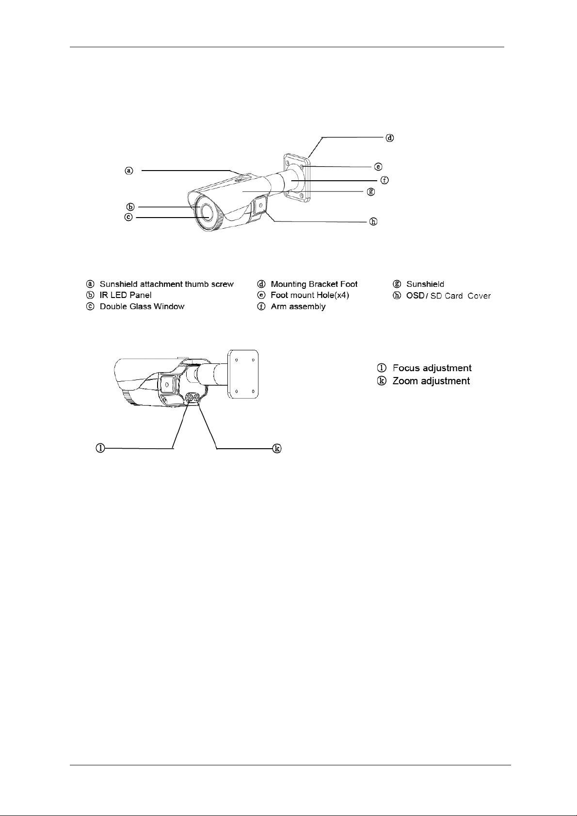
3.1. Front View ................................................................................................................... 7
3.2. Rear Side View ............................................................................................................. 7
4. VTC-IR40-N Installation ............................................................................................................ 8
4.1. Mounting The Camera .................................................................................................. 8
4.2. Connections ................................................................................................................. 8
4.3. Pan/Tilt Adjustment ...................................................................................................... 9
4.4. Setup Menu ............................................................................................................... 10
4.5. Removable Storage .................................................................................................... 11
5. Camera Software Installation .................................................................................................. 12
6. VTC-IR40-N Features .............................................................................................................. 15
7. IP Installer: Introduction ......................................................................................................... 15
8. Installing and Uninstalling ....................................................................................................... 15
8.1. Installing IP Installer .................................................................................................. 16
8.2. Uninstalling IP Installer ............................................................................................... 19
9. Using IP Installer .................................................................................................................... 21
9.1. Starting the Program .................................................................................................. 21
9.2. Search Product ........................................................................................................... 22
9.3. Automatic Network Setup ........................................................................................... 25
9.4. Using DHCP Server ..................................................................................................... 27
9.5. Using PPPoE .............................................................................................................. 28
9.6. Updating Firmware ..................................................................................................... 30
9.7. Filter Configuration ..................................................................................................... 32
9.8. Live View ................................................................................................................... 33
10. ENVI Admin Menu ................................................................................................................ 35
10.1. Entering Admin Menu ................................................................................................. 35
10.2. Admin Menu Structure ................................................................................................ 36
11. Quick Configuration .............................................................................................................. 36
11.1. Step 1: Changing Server Name .................................................................................... 36
11.2. Step 2: Time Setup ..................................................................................................... 36
11.3. Step 3: Network Setup ................................................................................................ 36
11.4. Step 4: IPCCTVDNS.COM ............................................................................................ 37
11.5. Step 5: Recording Configuration .................................................................................. 37
11.6. Finish......................................................................................................................... 37
1
Page 3

ENVI Series: VTC-IR40-N
12. System Configuration Menu .................................................................................................. 37
12.1. Server Name Setup..................................................................................................... 37
12.2. Date & Time............................................................................................................... 38
12.3. Admin Password ......................................................................................................... 39
12.4. Access Control ............................................................................................................ 39
12.5. User Registration ........................................................................................................ 39
12.5.1. Add ................................................................................................................. 39
12.5.2. Edit ................................................................................................................. 41
12.5.3. Delete ............................................................................................................. 41
13. Network Configuration .......................................................................................................... 41
13.1. Static IP Configuration ................................................................................................ 42
13.2. DHCP Client Configuration ........................................................................................... 42
13.3. PPPoE Configuration ................................................................................................... 43
13.4. Network Ports ............................................................................................................ 43
13.5. Bandwidth Control Configuration ................................................................................. 44
13.6. View Network Status................................................................................................... 44
13.7. Network Status Notify ................................................................................................. 45
13.8. IP-CCTV DNS Setup .................................................................................................... 46
13.9. Port Forwarding & UPnP ............................................................................................. 47
13.10. RTP/RTSP Setup ......................................................................................................... 48
14. Device Configuration ............................................................................................................ 49
14.1. Privacy Zone .............................................................................................................. 49
14.2. Camera & Motion ....................................................................................................... 52
14.3. Camera Configuration ................................................................................................. 54
14.3.1. Rate Control Mode ........................................................................................... 55
14.3.2. Image Quality Setup ........................................................................................ 55
14.4. Camera Control (Select Models)................................................................................... 55
14.5. DI (Sensor Input) / DO (Alarm Output) ........................................................................ 79
15. Advanced Configuration ........................................................................................................ 81
15.1. Advanced Services ...................................................................................................... 82
15.1.1. E-mail Service Configuration ............................................................................. 83
15.1.2. FTP (Buffered) Service Configuration ................................................................. 86
15.1.3. FTP (Periodic) Service Configuration .................................................................. 88
16. Recording Configur ation for Camera s with SD card ................................................................. 90
16.1. SD / MicroSD Card Configuration ................................................................................. 90
16.2. Recording Configuration with SD card .......................................................................... 93
17. Utilities ................................................................................................................................ 95
17.1. System Log ................................................................................................................ 96
17.2. Save Configuration ..................................................................................................... 96
2
Page 4

ENVI Series: VTC-IR40-N
17.3. Reboot ....................................................................................................................... 97
17.4. Factory Default ........................................................................................................... 97
17.5. System Update ........................................................................................................... 98
18. ENVI Series Viewer............................................................................................................. 101
18.1. Introduction ............................................................................................................. 101
18.2. Key Features ............................................................................................................ 101
18.3. System Requirement for PC....................................................................................... 101
19. Installing and Uninstalling ................................................................................................... 102
19.1. Installing ENVI Series Viewer .................................................................................... 102
19.1.1. Installing on Web Browser .............................................................................. 102
19.1.2. Manual Installation ......................................................................................... 104
19.2. Uninstalling ENVI Series Viewer ................................................................................. 105
19.2.1. Uninstalling with Program Menu ...................................................................... 105
19.2.2. Uninstalling on Control Panel .......................................................................... 106
20. Starting ENVI Series Viewer ................................................................................................ 107
20.1. Control Bar .............................................................................................................. 108
20.2. Channel Control Bar .................................................................................................. 109
20.3. OSD Channels Buttons .............................................................................................. 109
20.3.1. Saving as Image File ...................................................................................... 109
20.3.2. Saving as Video File ....................................................................................... 110
20.3.3. Manual Recording .......................................................................................... 110
20.3.4. Instant Playback ............................................................................................ 111
20.4. Extended Features .................................................................................................... 112
20.4.1. Pausing Live Video ......................................................................................... 112
20.4.2. FPS Control ................................................................................................... 112
20.4.3. Flip Control .................................................................................................... 113
21. EN-V-R: Introduction .......................................................................................................... 113
22. Requirements for Installation .............................................................................................. 114
22.1. EN-V-R Versions ....................................................................................................... 114
22.2. System Requirement for PC....................................................................................... 114
23. Installing EN-V-R ................................................................................................................ 115
24. Uninstalling EN-V-R ............................................................................................................ 118
24.1. Closing Active EN-V-R ............................................................................................... 118
24.2. Executing Uninstaller ................................................................................................ 119
25. Components of EN-V-R Program ......................................................................................... 120
25.1. EN-V-R Configurator ................................................................................................. 120
25.2. EN-V-R Service ......................................................................................................... 120
25.3. EN-V-R Controller ..................................................................................................... 120
25.4. EN-V-R System Tray Menu ........................................................................................ 120
26. Starting EN-V-R Configurator .............................................................................................. 121
3
Page 5

ENVI Series: VTC-IR40-N
27. Quick Start Guide ............................................................................................................... 122
27.1. EN-V-R Configurator User Interface ........................................................................... 122
27.2. Searching for IP Devices ........................................................................................... 123
27.3. Registering IP Devices .............................................................................................. 125
27.4. Viewing Live Video ................................................................................................... 127
27.5. Recording Video ....................................................................................................... 129
28. ENVI Smart Player .............................................................................................................. 133
28.1. Introduction ............................................................................................................. 133
28.2. Key Features ............................................................................................................ 133
28.3. System Requirement for PC....................................................................................... 134
29. Installing and Uninstalling ................................................................................................... 134
29.1. Installing Smart Player .............................................................................................. 134
29.1.1. Manual Installation ......................................................................................... 135
29.2. Uninstalling Smart Player .......................................................................................... 136
29.2.1. Uninstalling on Prog ram Menu ........................................................................ 136
30. Configuring & Viewing Player .............................................................................................. 146
30.1. Main Window View ................................................................................................... 147
30.2. Connecting to NVR Player ......................................................................................... 148
30.3. Creating a Group ...................................................................................................... 148
31. Searching Video ................................................................................................................. 150
31.1. Searching Video ....................................................................................................... 150
31.2. Daily Search ............................................................................................................. 150
31.2.1. Search Mode .................................................................................................. 151
31.2.2. GO to Time Position ....................................................................................... 151
31.3. Condition Search Mode ............................................................................................. 151
31.3.1. Advanced Search Mode .................................................................................. 152
32. Video Playback C ontrols ...................................................................................................... 153
33. Extra Features ................................................................................................................... 154
33.1. Window Control ........................................................................................................ 154
33.2. Recording Period ...................................................................................................... 154
33.3. Backup .................................................................................................................... 155
33.4. Snapshot ................................................................................................................. 156
33.5. Print ........................................................................................................................ 157
33.6. Ratio Display ............................................................................................................ 157
34. EN-V-R Configuration ......................................................................................................... 158
34.1. System, Network Configuration ................................................................................. 158
34.1.1. Configuring System name ............................................................................... 159
34.1.2. System, Network Configuration - Admin password ........................................... 160
34.1.3. System, Network Configuration - Access Control .............................................. 160
34.1.4. System, Network Configuration - HTTP Port..................................................... 161
4
Page 6

ENVI Series: VTC-IR40-N
34.1.5. System, Network Configuration - IP-CCTV DNS ................................................ 161
35. IP-CCTV DNS Registration .................................................................................................. 162
36. IP-Device Registration ........................................................................................................ 167
36.1. IP-Device Registration (Manual) ................................................................................ 168
36.2. IP-Device Registration (Automatic) ............................................................................ 170
IP-Device Modific ation ................................................................................................. 172
36.3. IP-Device Deletion .................................................................................................... 174
36.4. IP-Device Homepage ................................................................................................ 174
36.5. Camera Management ................................................................................................ 174
36.5.1. Configure Camera Name and Information ........................................................ 175
36.5.2. Camera Resolution, Quality ............................................................................. 176
36.5.3. Configure Camera Recording Condition ........................................................... 177
36.5.4. Alarm, Event Configuration ............................................................................. 180
36.6. User Management .................................................................................................... 181
36.6.1. User Registration ........................................................................................... 182
36.6.2. User Modification ........................................................................................... 182
36.6.3. User Deletion ................................................................................................. 183
36.7. Disk Setup ............................................................................................................... 183
36.7.1. Disk Setup ..................................................................................................... 183
36.7.2. Disk Quota Modification and Deletion .............................................................. 183
36.7.3. Disk Mode Change ......................................................................................... 184
36.8. Utilities .................................................................................................................... 186
36.8.1. Email account Configuration ........................................................................... 186
36.8.2. About Program .............................................................................................. 187
37. Using EN-V-R Controller ...................................................................................................... 188
38. Connecting to EN-V-R ......................................................................................................... 189
38.1. PC with EN-V-R installed ........................................................................................... 189
38.2. PC without EN-V-R.................................................................................................... 190
5
Page 7
1. Box Contents
1) VTC-IRE40-N Long range Weatherproof IR Bullet camera
2) Mounting Accessories
3) VT-MD-2VOC (Secondary Video Output Cable)
4) ENVI Series CD & Mounting Template
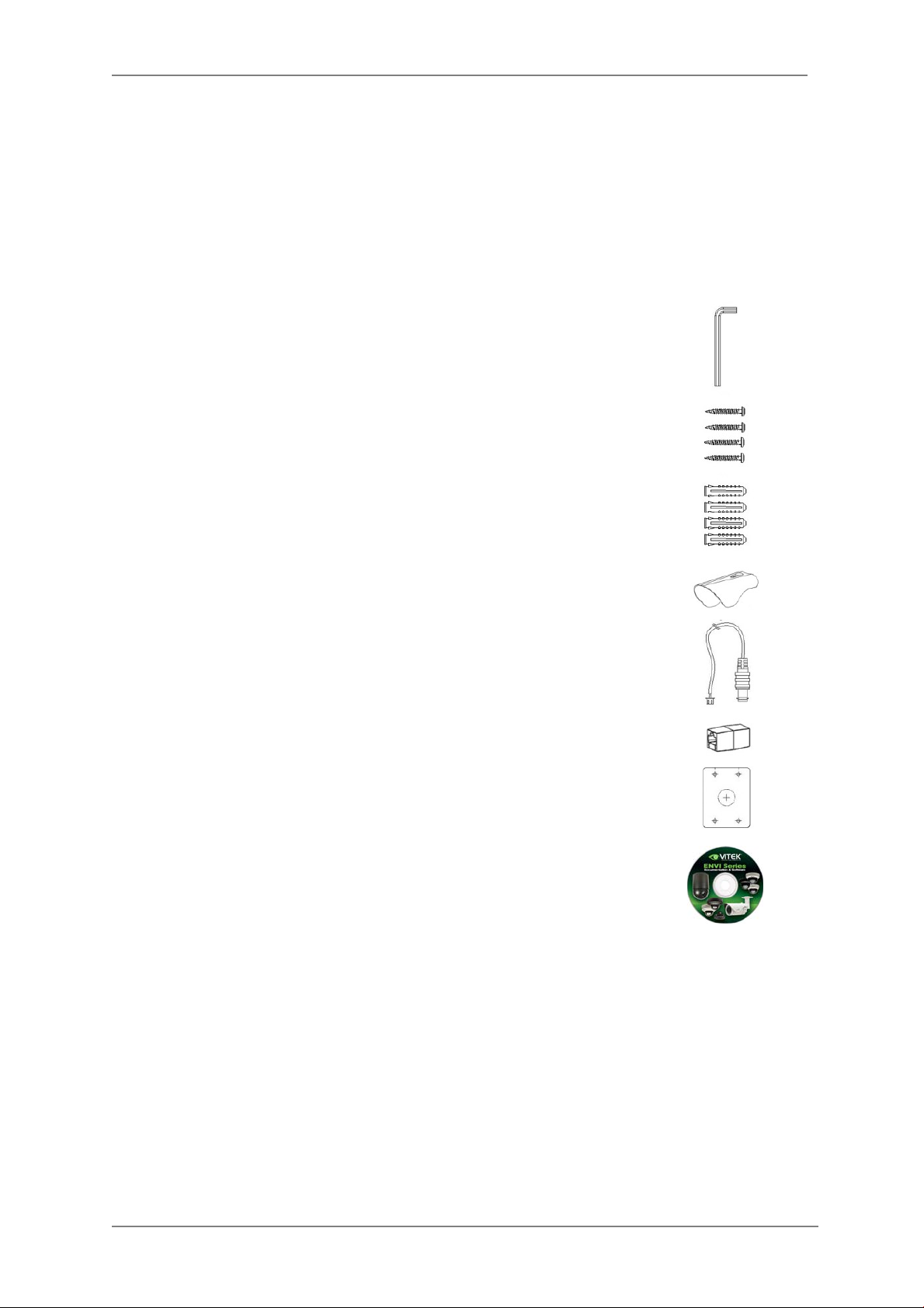
2. Included Acces sories
3mm Hex L-wrench
Qty: 1
Wall mounting screws
Qty: 4
Anchors
If necessary, use the anchor to help secure the self tapping screws.
Qty: 4
Sunshield with Attachment thumb screw
Qty: 1
VT-MD-2VOC (Secondary Video Output Cable)
For viewing video image during installation.
Qty: 1
RJ45 Coupler
Qty: 1
Mounting Template
Qty: 1
ENVI Series CD
Qty: 1
ENVI Series: VTC-IR40-N
6
Page 8
ENVI Series: VTC-IR40-N
3. VTC-IR40-N Layout
3.1. Front View
3.2. Rear Side View
7
Page 9
4. VTC-IR40-NInstallation
• Make sure the power is not applied before the installation.
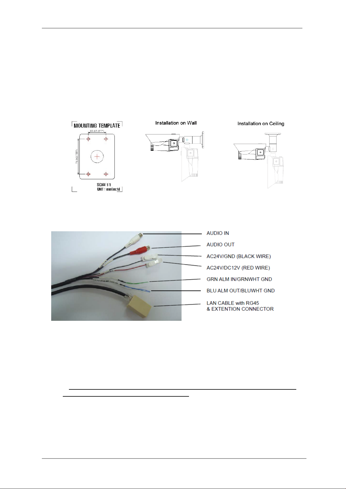
4.1. Mounting The Camera
1. Drill 4 holes into the wall or ceiling using the supplied template
2. Insert the anchors into the drilled holes
3. Match (foot mount holes) to the drilled holes
4. Affix the mounting bracket by using supplied screws
ENVI Series: VTC-IR40-N
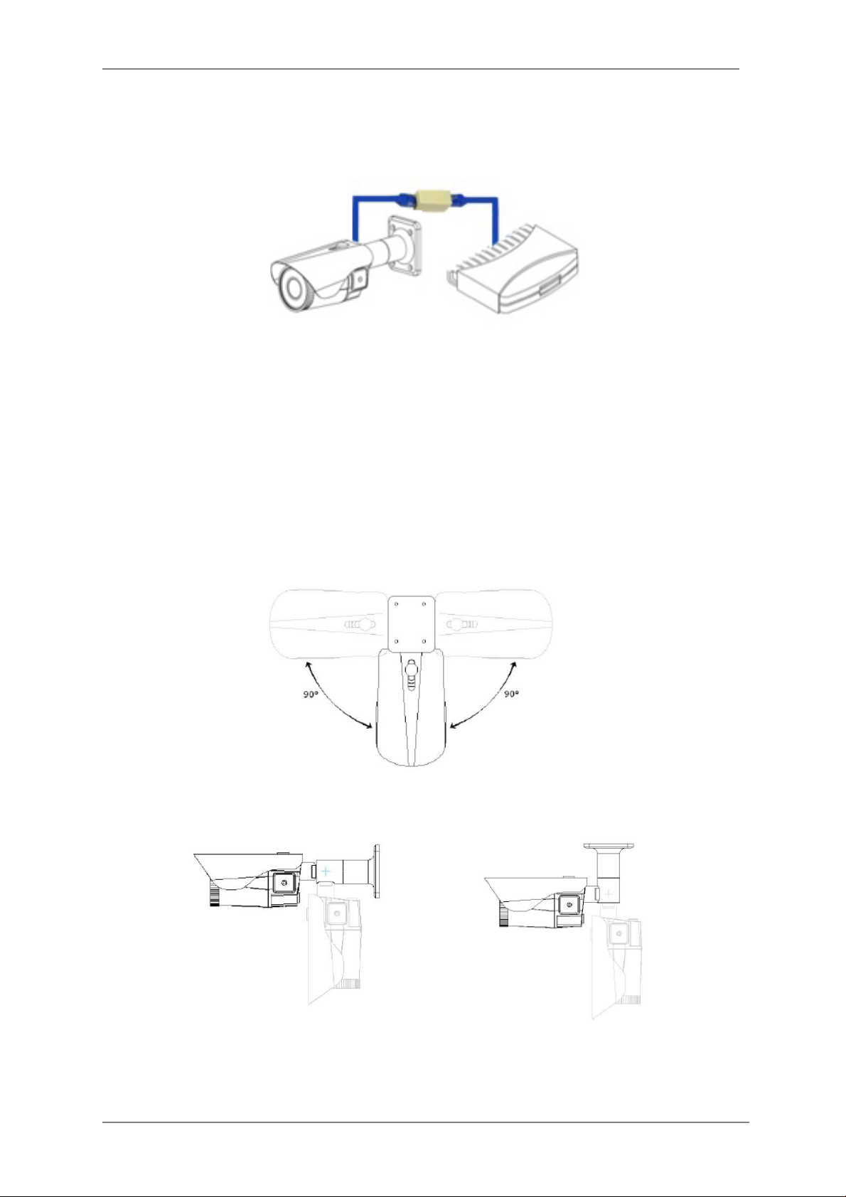
4.2. Connections
1. Power
Depending on the type of installations, apply power to the camera by one of the three
options below.
a) Via Ethernet – Use only with POE switch (100 Meters max distance)
b) 12VDC - Use with 12VDC 1A ** SEE IMPORTANT NOTES BELOW **
c) 24VAC- Use with 24VAC for longer distances.
It is required that the polarity-matched connection is made for 12VDC supply ,
**
otherwise IR LEDs will not operate at night. **
Primary and secondary grounds are completely isolated to avoid possible ground-loop
problems.
8
Page 10
ENVI Series: VTC-IR40-N
2. Ethernet Connection
Insert one end of the Ethernet cable into the network jack of your camera, and insert the other
end into the data port (switch, router, etc)
3. Alarm Connections
This camera support Alarm IN/OUT, Green = alarm IN, Blue = alarm OUT. (For more
information, refer to Section 14.5DI (Sensor Input) / DO (Alarm Output) on page 79)
4. Audio In/Out
This camera supports RCA Audio IN/OUT, (Audio IN White, Audio OUT Red)
4.3. Pan/Tilt Adjustment
1. Tilt Adjustment
Pan is limited to +/- 90°.
2. Tilt Adjustment
Tilt is limited to 0° (2°) min ~ 90° max.
9
Page 11
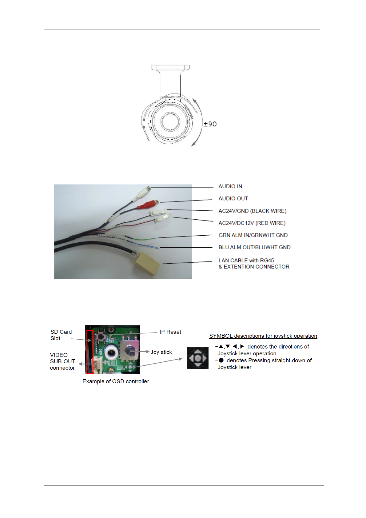
3. Camera Rotation
Inclination limited to +/-90° max.
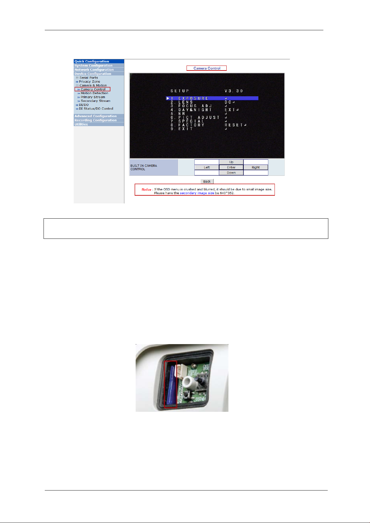
4.4. Setup Menu
ENVI Series: VTC-IR40-N
1. Accessing the Setup Menu & Controls
The Setup menu can be accessed and controlled in two ways:
a) Via the OSD control joy stick located on the side of the camera
10
Page 12
ENVI Series: VTC-IR40-N
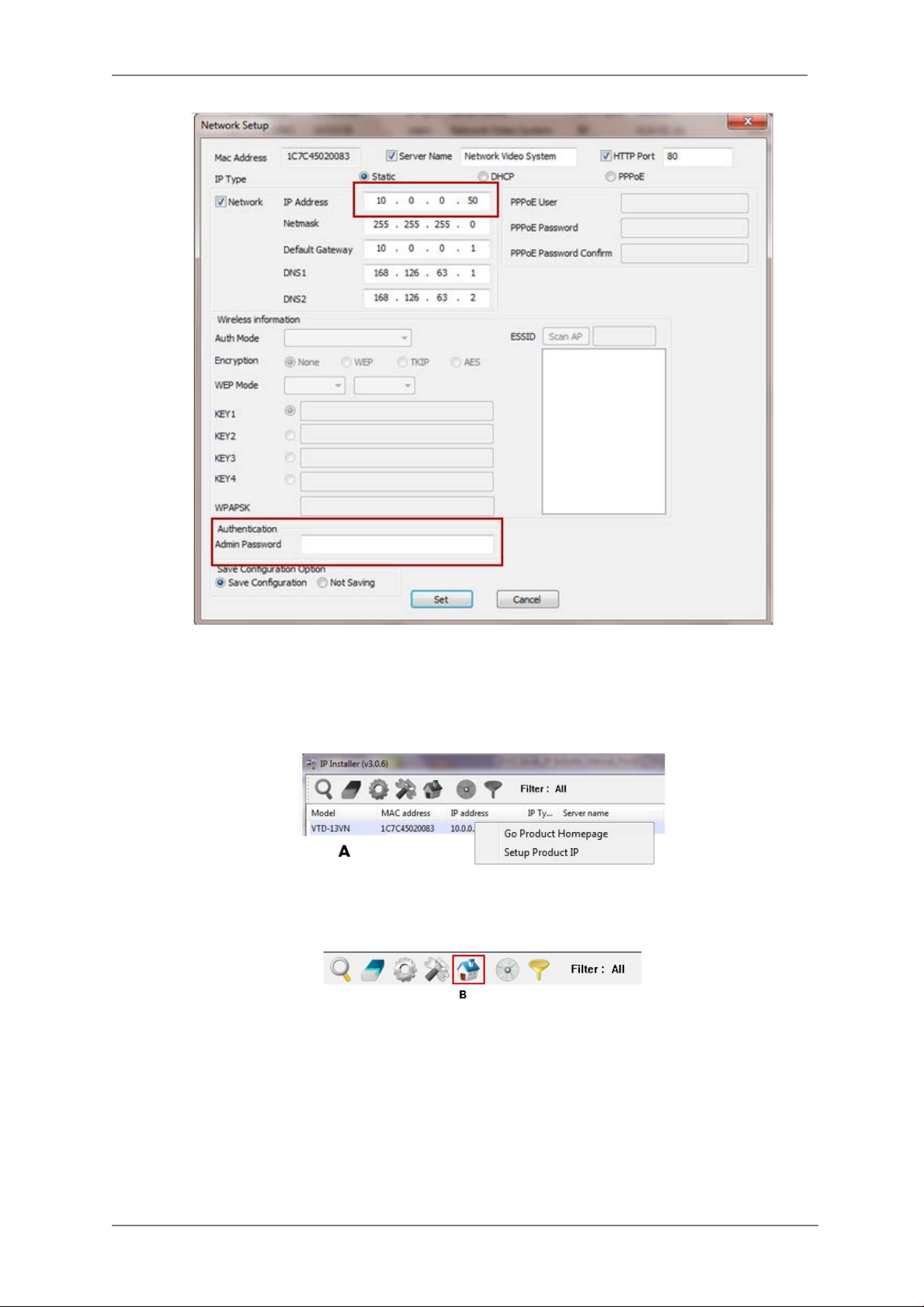
b) Via the Web-Admin, Device Configuration> Camera & Motion> Camera Control.
NOTICE: If the OSD menu is crushed and blurred, is due to small image size. Please have the
secondaryimage size at 640x352
NOTE: For further information on OSD menu, refer to Section14.4Camera Control (Select
Models) on page 55.
4.5. Removable Storage
For recording directly on the camera you will need to install a SD card, this will allow you to
play video directly from the camera. (** Please use only class 10 SD cards).
a) With the power disconnected insert the SD memory card as shown below (the SD card
willneed to be formatted.(refer to Section 16.1SD / MicroSD Card Configurationon page
90for instructions on Formatting)
11
Page 13

ENVI Series: VTC-IR40-N
5. Camera Software Installation
1. Run IP Installer Software from the CD program on a computer that is on the same network
as the IP camera.
2. StartIP Installer, by double clicking t he icon “IP Installer”
3. After the program has started, the main window of IP Installer program will appear on the
screen as shown belo w.
4. Search for the installe d camera on the network by clicking the search product icon, the
camera should appear as the image below. The de fault IP address is 10.20.30.40
5. To assign an automatic IP address to this camera within the network, click the “Automatic IP
Setup” icon
6. Verify the Automat ic IP address provided, enter the default password root and then click Set
as shown below.
12
Page 14
ENVI Series: VTC-IR40-N
7. After the camera was configured by the program automatically, you will be able to get access
by
a) Right click over the camera information, “
b) Click over the icon “
8. From the Home Page, you can “
Connect Product Homepage
Live View”
Go Product Homepage
”
or administrate
“Admin”
”
the camera.
13
Page 15
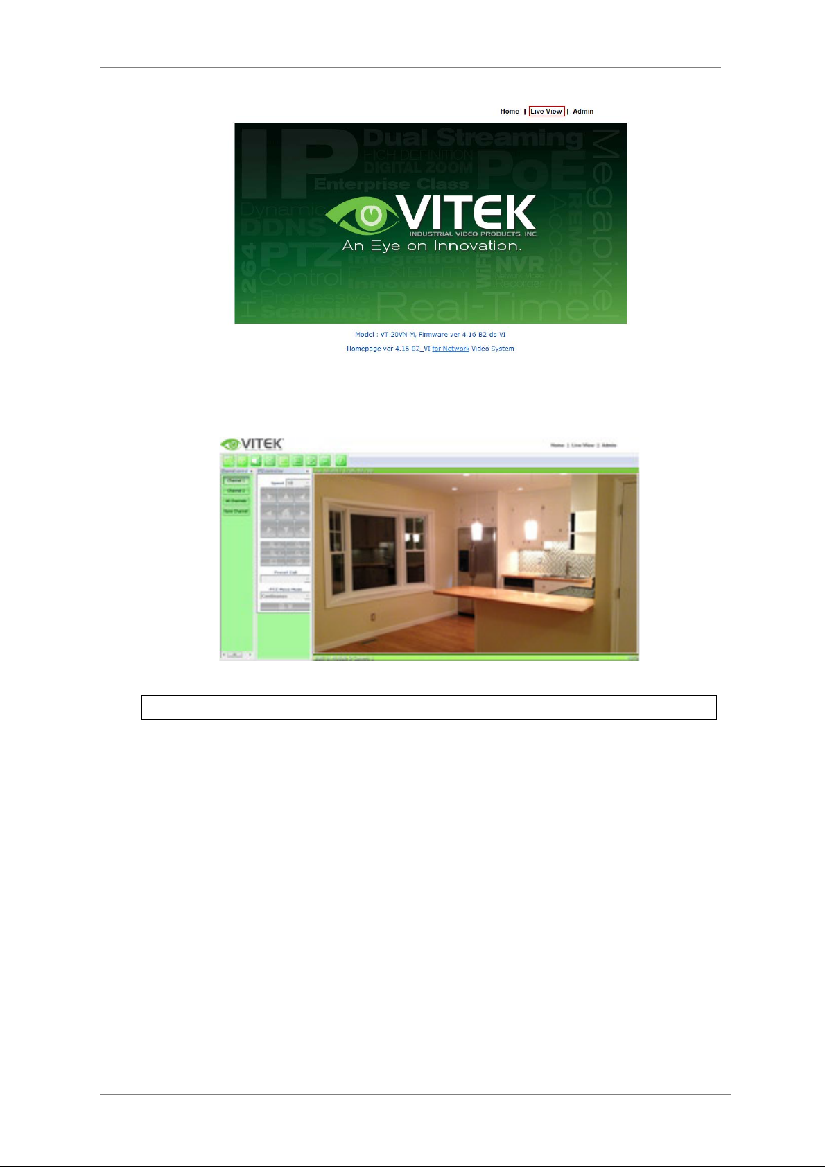
On Live View you will be able to see live video from your camera.
ENVI Series: VTC-IR40-N
NOTE: For more information, refer to
Section 10. ENVI Admin Menu on page 35
.
14
Page 16

ENVI Series: VTC-IR40-N
6. VTC-IR40-N Features
1.3 & 2.0 MegaPixel Vandal Resistant Day/Night IR Bullet Cameras with 150’ Range
• 1/3” 1.3 & 2.0 Meg apixel Progres sive Scan CMOS image sensors
• Up to 30fps live view @ 1920x1080p (2.0 MegaPix el Models) / 1280x1024 (1.3 Meg aPixel
Models)
• 2.8-10mm Varifocal Auto Iris Lens
• Integrated 850nm Infrared LEDs with up to 150’ Range
• Dual Glass Compartments to Eliminate Glare
• 2.8-10mm Varifocal DC Auto Iris IR Lens
• Heavy Duty IP68 rated weather resistant aluminum construction
• Secondary Video Output & OSD Control Joystick are accessible inside a Gasket sealed
removable side panel
• Externally adjustable Focus & Zoom with clutch to eliminate over-tightening
• 3D-DNR Noise Reduction
• 16:9 (2.0 MegaPixel Models) / 4:3 (1.3 MegaPixel Models) Video format
• Secondary video o utput for installation & maintenance
• Auto True Day Night (TDN) without focus shift is achieved with dual filter switch function
• H.264/MJPEG Dual Streaming
• Full duplex 2 way audio, Alarm IN/OUT
• Minimal Latency w/Max 16 User Connections
• Onvif PSIA Compliance
• SD memory card slot for Local recording
• 12VDC/24VAC & PoE (Power over Ethernet) Operation
7. IP Installer: Introduction
IP Installer is a proprietary utility program for VitekIP products. It enables users of Vitek products
to search their network for any Vitek network camera, video server, or network video recorder no
matter what IP address it has. By using IP Installer, u sers will be able to facilitate network setup
process for Vitek products deployment.
Runs on Microsoft Windows operating system (XP, Vista, 7, 8)
Search for Network Cameras, Video Servers, and Network Video Recorders
Capable of firmware updating
Support automatic and manual IP setup
8. Installing and Uninstalling
** It’s recommended to install this program as an administrator **
15
Page 17
ENVI Series: VTC-IR40-N
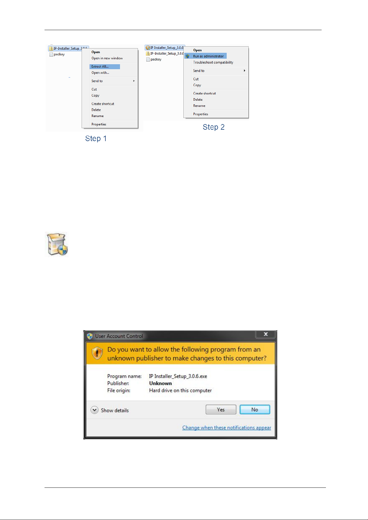
8.1. Installing IP Installer
If the program is started from the CD supplied with Vitek products, insert the CD in to CD/DVD tray
and check the installation file. If it is download or copied from the Internet or any other media,
locate the file from the PC’s hard drive. You will see the icon as shown with the file name IP
Installer_Setup_x.x.x.exe. The act ua l file nam e in your case may vary as the version changes.
Double click the icon to star installation.
You may be prompted to co ntinue running the installation program.
Click Yes button, then the following window will be shown on the screen.
16
Page 18
ENVI Series: VTC-IR40-N
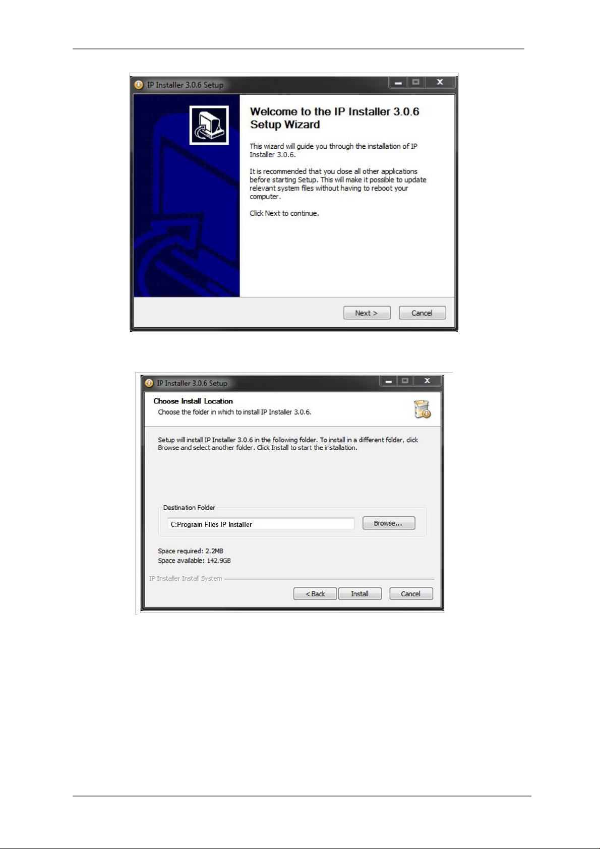
To continue the installation, click Next. The following window will be displayed for location to
install.
The default location for installation is C:\Program Files\IP Installer. It is recommended to install
in this folder, if you want to change it to a different location, click the Browse button to choose
location. Now click the Install button. You will see the progress of theinstall as shown below.
17
Page 19
ENVI Series: VTC-IR40-N
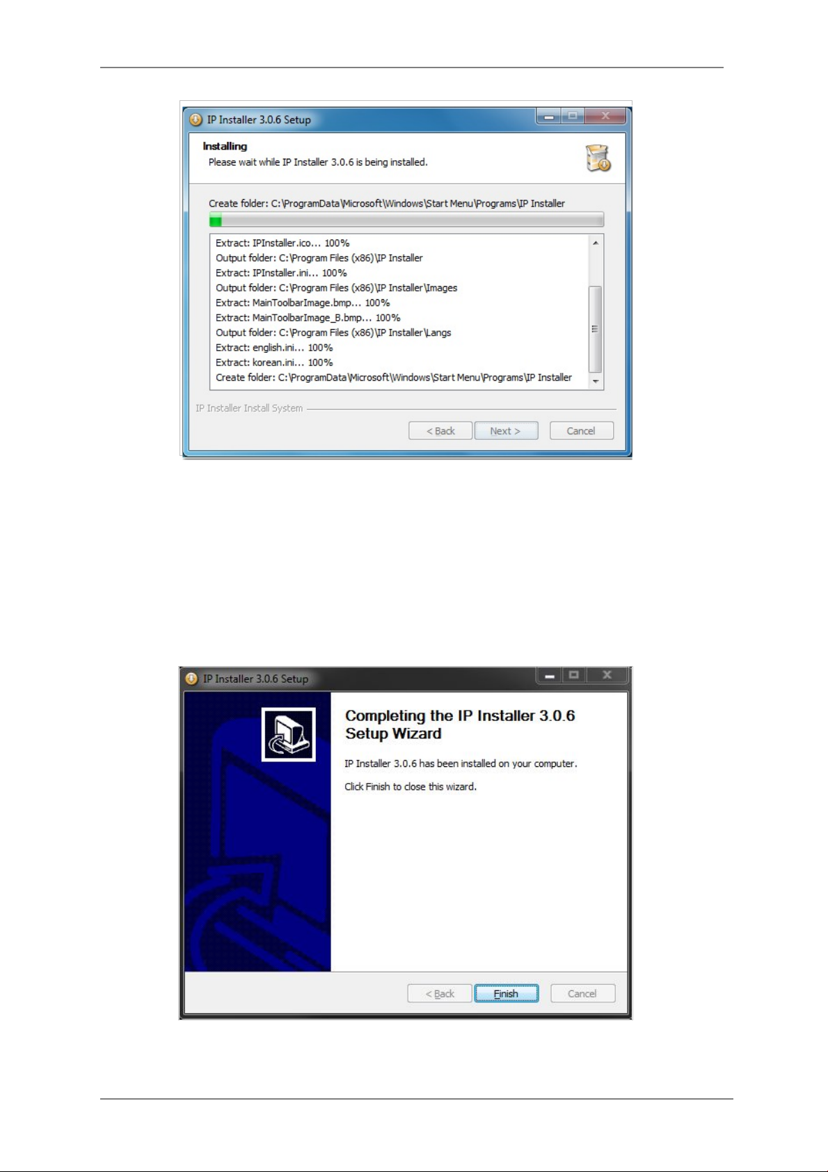
When the files are done copying, the following window will be shown. Click the Finish button to
complete the installation.
18
Page 20
ENVI Series: VTC-IR40-N
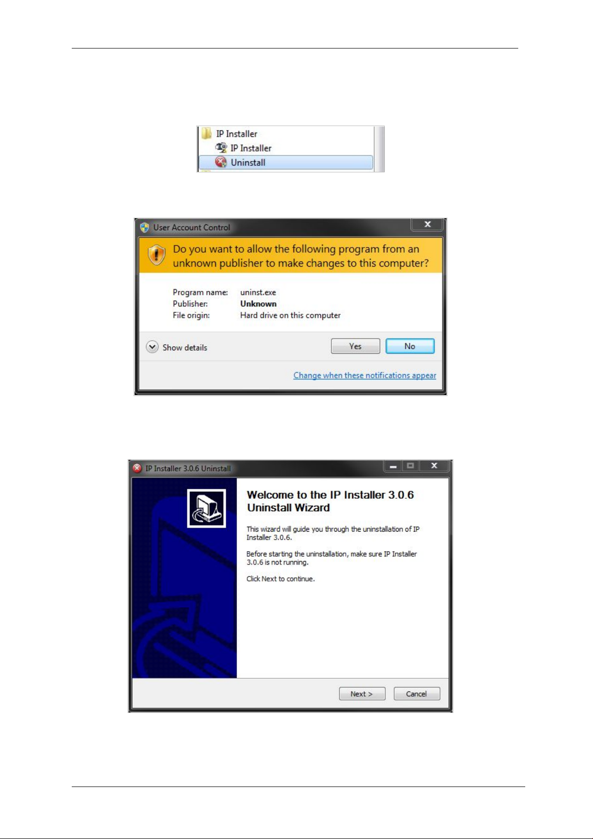
8.2. Uninstalling IP Installer
If you want to remove the IP Installer program from your PC, click Start > All Programs > IP
Installer > Uninstall.
You may be prompt to continue running theuninstall program.
Click onthe Yes button, then the following window will be shown on the screen.
Click on the Next butt on and you will see the following window.
19
Page 21

ENVI Series: VTC-IR40-N
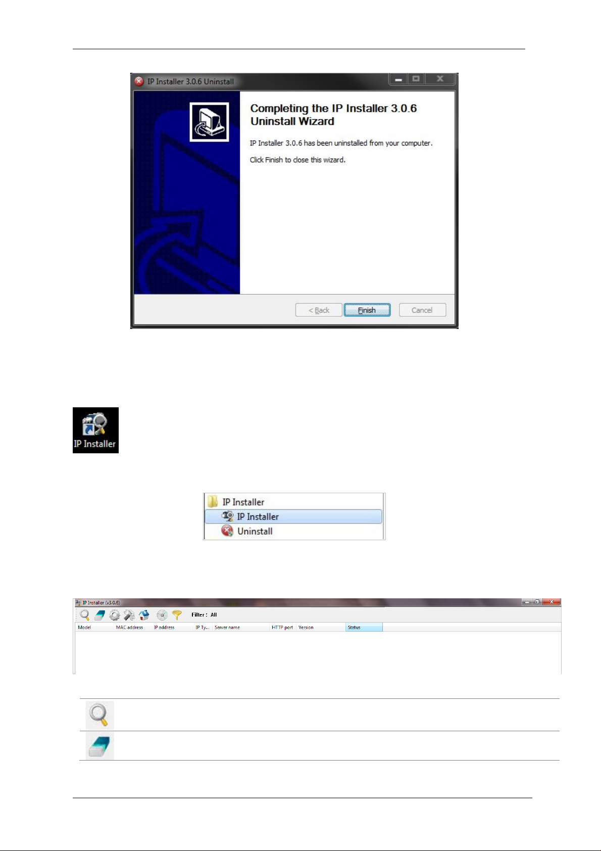
Click on the Uninstall button to start removing the IP Installer program from your comput er.
The following window will be displayed.
Click on the Finish button to close the window
20
Page 22
ENVI Series: VTC-IR40-N
9. Using IP Installer
9.1. Starting the Program
Once IP Installer program has been installed on your computer, a shortcut icon
should be created on the desktop of your computer.You can star t IP Installerby
double clicking the icon.
Or you can also start the program by clicking Start > All Programs > IP Installer > IP
Installeras shown below.
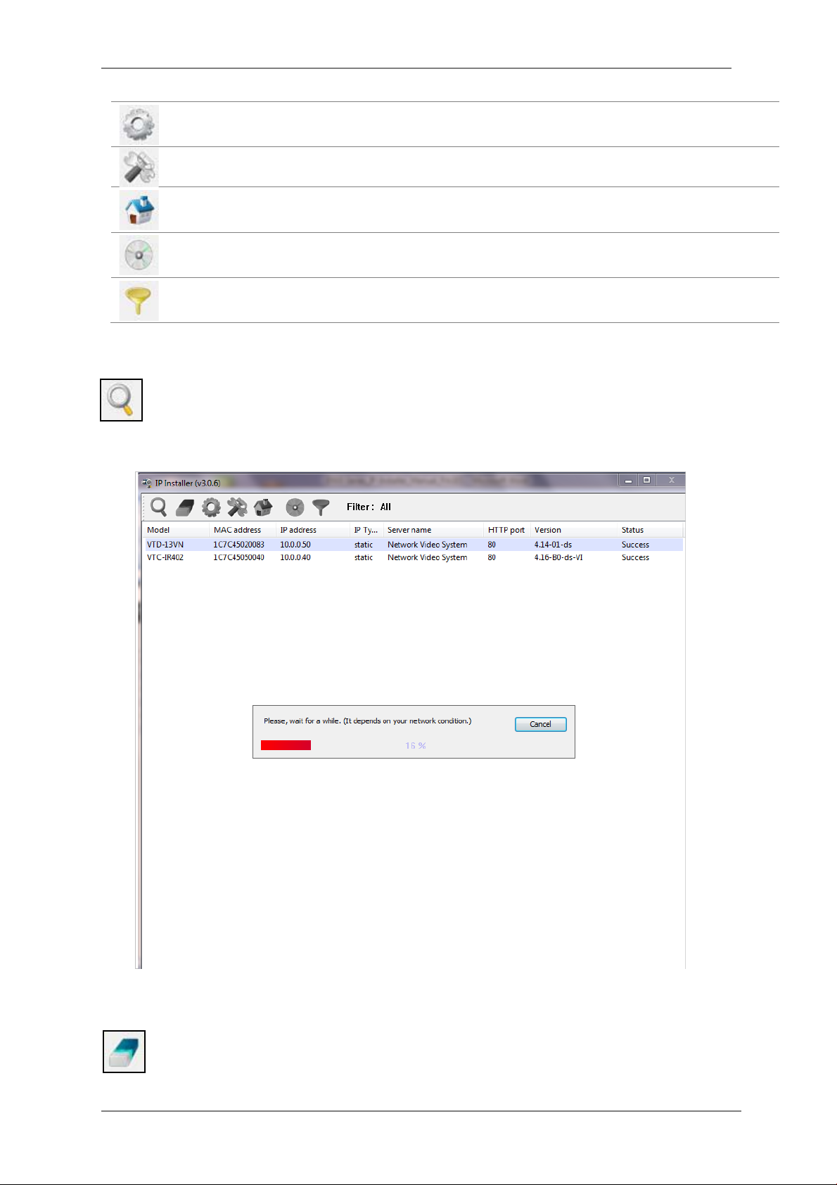
After the program has started, the main window of IP Installer program will appear on the
screen as shown belo w. There are no network devices shown,as it is the first time running the
program and nothing has been registe red.
Search Product
Clear Product List Clear the Vitek products list created by searching the network.
21
Scan the network and shows the list of all the Vitek products that IP
Installer program found.
Page 23
ENVI Series: VTC-IR40-N
Automatic IP Setup Configure the network setting of selected IP device in Automatic mode.
Manual IP Setup Configure the network setting of selected IP device in Manual mode.
Connect Product
Homepage
Update Firmware Update the firmware of the selected IP device.
Filter Configuration Define the range of MAC and IP addresses to search.
9.2. Search Product
Make sure that your Vitek products are powered and connected to the network, and then
click the Search Product button. A status window will pop up to show the progress of
the search. Wait until it reaches 100%, or you may press the Cancel button to stop the
search at any given timeand proceed with the results made until that moment.
Connect to the server homepage of the selected IP device.
After searching is completed 100%, the IP Installer program will display the IP devices found.
If you want to clear the list of the IP Devices from the window, click Clear Product List
button from the Main Toolbar .
22
Page 24
ENVI Series: VTC-IR40-N
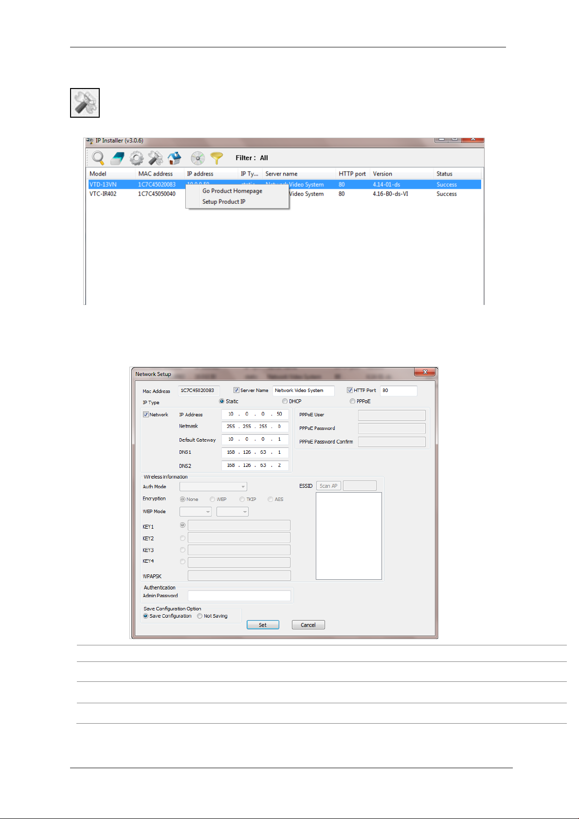
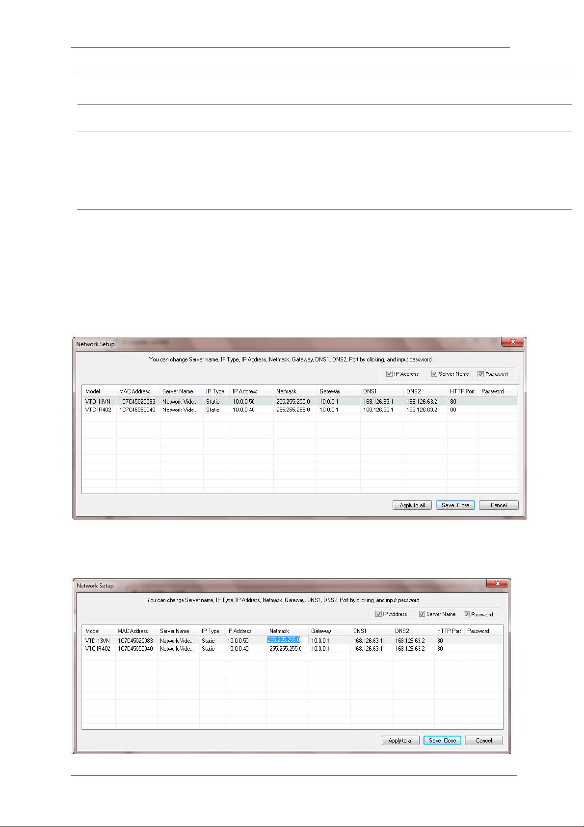
Manual Network Setup
Configuring the network parameters of the devices in the list can be started either by
highlighting and right clickingmouse button or by clicking Manual IP Setupbutton on the
main Toolbar.
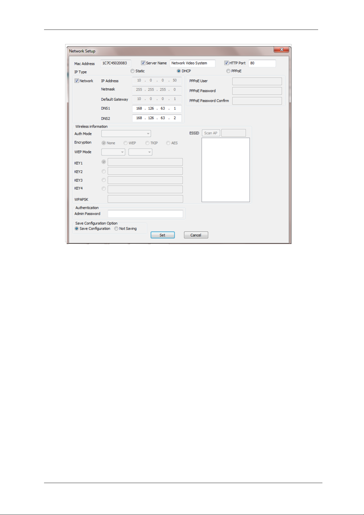
When one IP device is selected, the following screen will appear
MAC Address MAC address of the selected device is shown.
Server Name Input desired name of camera i.e. Lunch Room
HTTP Port Input port number to access IP devices homepage via web. Default port is 80
IP Type Select the type of address (Static / DHCP / PPPoE) Use STATIC for manual IP setup
23
Page 25
ENVI Series: VTC-IR40-N
Network
Authentication
(Admin Password)
Save Configurati on
Option
Click Set button to ap ply the changed values to IP device. If you don’t want it, click Cancel button.
When two or more IP devices are selected
You can select two or more IP devices at the same time by clicking one after another while CTRL
key is pressed. The result is shown as below.
To configure the network parameters of those devices, click the right mouse button or click
Manual IP Setup icon on the main Toolbarwith multiple IP devices selected as shown above.
Then the following window will show up.
General network parameters are required in this part. Please contact your network
administrator for detail.(IP Addr es s , Netmask, Default Gateway, DNS1, DNS2)
Password for the IP device.
(Default password for Vitek products is “root” unless already changed)
Select whether the configured contents is to be saved in the Camera memory or not.
• Save Configuration: Changed values will be saved in the Camera memory of the
device, which means the changes are permanent.
• Not Saving: Changed values w ill not be saved in the Camera memory, which
means if the IP device is turned off the changes are lost and the previous setting
will be applied back.
You can modify the value of each changeable field by clicking it. The following shows an example
of entering a new value to a field.
24
Page 26
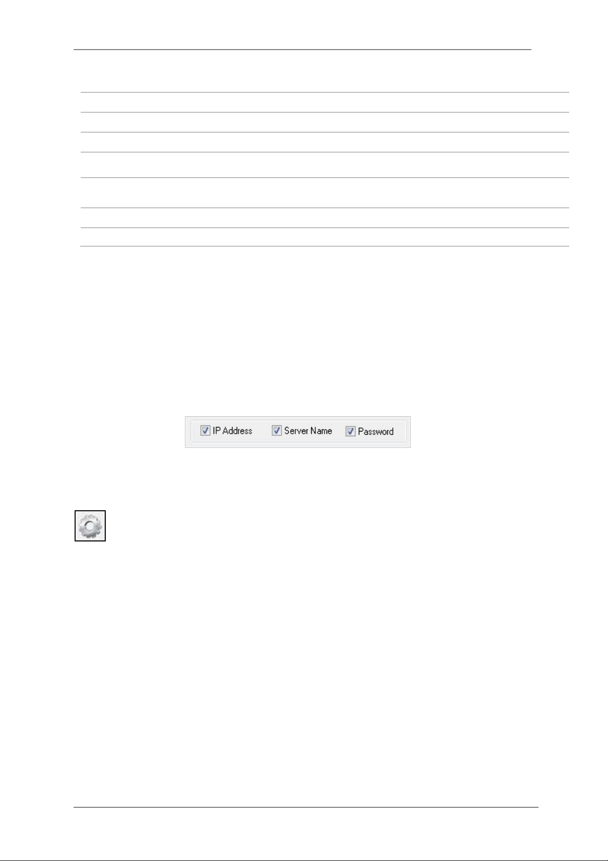
ENVI Series: VTC-IR40-N
Static
Model Model Numbers of the IP devices that you selected.
MAC Address MAC address of the selected device is shown.
Server Name Name of the selected IP device.
IP Type
IP address, Netmask,
Gateway, DNS1, DNS2
HTTP Port HTTP port number of the IP device for web access to homepage.
Password Password for the IP device.(Default password for Vitek products is “root”)
If you click Apply to all button after changing just a field of one IP de vice, the remaining IP
devices will have the same value for that parameter. In this case, each device’s Server name and
IP Address field will have +1 incremented value added to the original value. For example, if the
first IP device has been given the server name of NetCam and Apply to all button is pressed, it
will be automatically changed to NetCam1 and the next IP device will have NetCam2 and so on.
The same applies to the IP address field.
How to assign IP address to the device (Select
Setup)
General network parameters are required in this part. Please contact your
network administrator for detail.
here for Manual IP
For Password field, the ente red information doesn’t increment but will use the same data.
In using Apply to all, you can choose which field is affected. Put check marks only on the field
you want to use this automatic action as below.
Click Save & Close button to save the changed values in the camera memory of all the IP devices
and close the Network setup window.
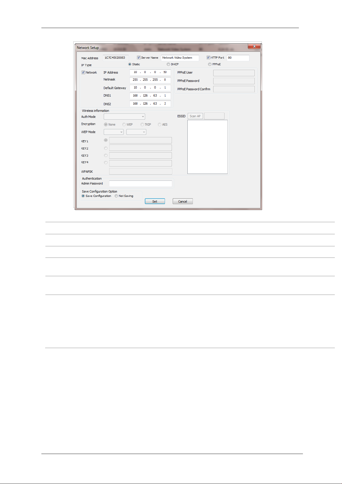
9.3. Automatic Network Setup
Configuring the network parameters of the devices in the list can be started either by
clicking right mouse button or by clicking Automatic IP Setupbutton on the main
Toolbar. Before starting the setup, you first need to choose the one to be configured. In
this setup mode, IP Installer program checks your local network and assigns available IP addresses
to the IP devices. You have a choice of using those automatically assigned IP addresses, or you
can just enter other IP addresses as you desire.
25
Page 27
ENVI Series: VTC-IR40-N
Server Name Name of the selected IP device.
HTTP Port HTTP port number of the IP device for web access to homepage.
IP Type How to assign IP address to the device (Select Static here for Manual IP Setup)
Network
Authentication
(Admin Password)
Save Configurati on
Option
Click Set button to apply the changed values to IP devi c e. If you don’t want it, c lick Cancel button
to restore the previous values.
General network parameters are required in this part. Please contact your network
administrator for detail. (IP Address, Netmask, Default Gateway, DNS1, DNS2)
Password for the IP device. (Default password for Vitek products is “root”)
Select whether the configured contents is to be saved in the Camera memory or not.
• Save Configuration: Changed values will be saved in the Camera memory of the
device, which means the changes are permanent.
• Not Saving: Changed values w ill not be saved in the Camera memory, which
means if the IP device is turned off the changes are lost and the previous setting
will be applied back.
26
Page 28
ENVI Series: VTC-IR40-N
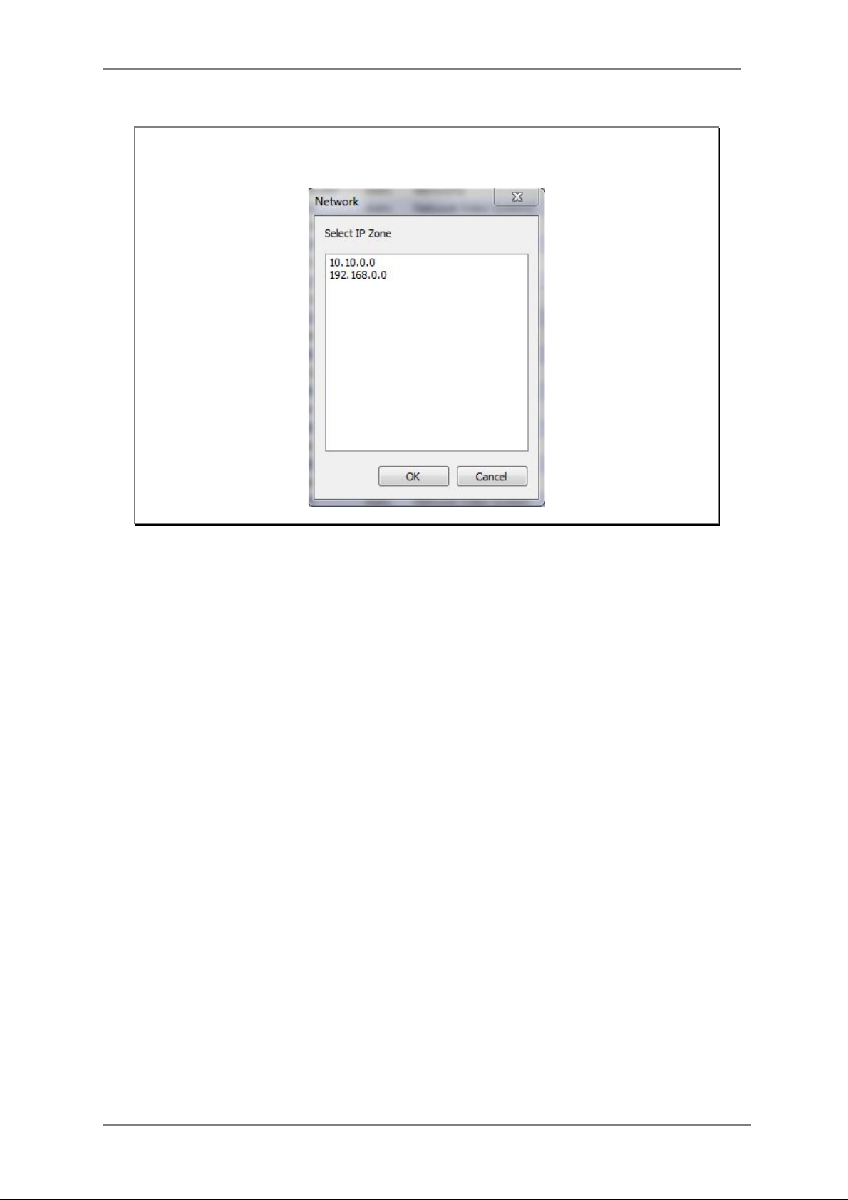
Note: If your network has more than one IP address Zone at the same time, the
confirmation window will be displayed as below. You need to choose the one you
are going to use for your IP devices.
9.4. Using DHCP Server
If your network has a DHCP server running for assigning IP addresses, you may choose to let it
assign IP addresses to the IP devices on the list. To do that, first open the Network Setup window
either by Manual IP Setup or Automatic IP Setup procedure. Choose DHCP in “IP Type ”
selection, then IP Address, Netmask, Default Gateway field in Network setup area on the
window will be disabled to input as shown below.
27
Page 29
ENVI Series: VTC-IR40-N
For setting up other fields on the setup window, refer toSection0Manual Network Setupon
page 23. After filling the fields wit h appropriate values, click Set button to apply the changed
values to IP device. If you don’t want it, click Cancel button to restore the previous values.
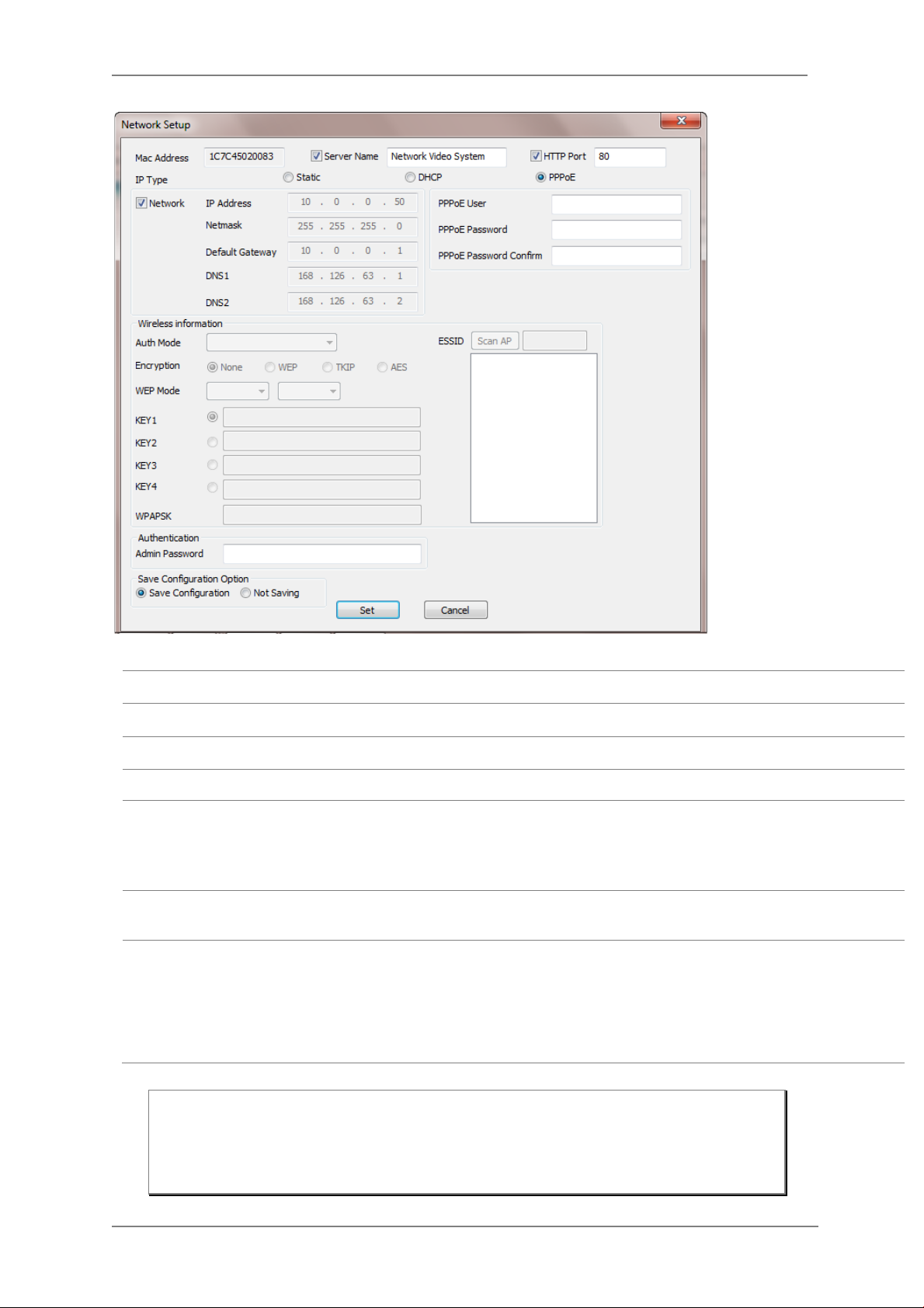
9.5. Using PPPoE
If your network environment is based o n PPPoE connection, you’ll need to choose PPPoE on IP
Type selection. Fir st open the Network Setup window either by Manual IP Setup or Automatic
IP Setup procedure. Choose PPPoE in IP Type selection, and then all the fields in Network
setup area on the window will be disabled. The network settings such as IP A d d ress, Netmask,
Default Gateway and DNS are no longer available to enter. You only need to enter the Server
Name, HTTP Port num ber, and login authentication for your PPPoE connection.
28
Page 30
ENVI Series: VTC-IR40-N
MAC Address MAC address of the selected device is shown.
Server Name Name of the selected IP device.
HTTP Port HTTP port number of the IP device for web access to homepage.
IP Type How to assign IP address to the device (Select PPPoE in this mode)
User Authentication for PPPoE Connection.
• PPPoE User: Enter User ID.
PPPoE
Authentication
(Admin Password)
Save Configurati on
Option
• PPPoE Password: Enter Password for the User ID.
• PPPoE Password Confirm: Enter the same Password again.
Password for the IP device.
(Default password for Vitek products is “root” unless already changed)
Select whether the configured contents is to be saved in the Camera memory or not.
• Save Configuration: Changed values will be saved in the Camera memory of the
device, which means the changes are permanent.
• Not Saving: Changed values w ill not be saved in the Camera memory, which
means if the IP device is turned off the changes are lost and the previous setting
will be applied back.
Note: After setting up the network for the IP devices, make sure the IP devices are
accessible on the network from your computer. It can be done by running Live
View function of the homepage of the IP device’s built-in server. Refer to
9.8
Live View
29
on page 33
for more information.
Section
Page 31

ENVI Series: VTC-IR40-N
9.6. Updating Firmware
Once IP devices are searched and shown on the screen as functioning successfully, you can update
the firmware of them in “IP Installer” program. To do that, first check the firmware version of the
device, which you can find on the IP Installer window.
In the above picture, the firmware version of this product is 4.14-01-ds while the latest
firmware version available is 4.16-B0-ds-VI as you could see at Vitek’s homepage
(
http://www.vitekcctv.com/Downloads.asp). If you decide to update the firmware, first
create a folder on your computer for the update firmware, than download the latest firmware to
that folder.
Then select the IP device to be updated on IP Installer window, then click Update Firmware
button from the toolbar. The following window will be displayed.
You may find the Password field is empty on the window shown above. If so, click the Password
field of the IP device and enter the proper password for the device. You are not allowed to update
the firmware if the correct password is not provided.
After the password is entered, the Star t U pdate button will be enabled now. Click the button to
see the following window for selecting the folder where the file has been saved.
than click
OK.
Highlight the folder
30
Page 32

ENVI Series: VTC-IR40-N
After clicking OK the following window will be displayed.
Note: Do not CLOSE window until completed, to avoid permanent damage to the camera.
You can also select multiple IP devices at the same time, and have them start firmware updat ing in
a single step. Select the files to update by holding CTRL key and selecting which IP devices to
update
Click Start Update button. You will see the update window brought up with multiple IP device s
listed.
The rest of the procedure is the same as in the firmware update case for a single IP device.
31
Page 33

ENVI Series: VTC-IR40-N
9.7. Filter Configurati on
When you need to search only for the IP device having a specific range of MAC or IP
addresses, you can do it by using this feature. To set the search condition, click Filter
Configuration but ton on the Toolba r, then the following window will show up on the
screen.
The first six HEX characters are already filled in with 1C:7C:45, which is the MAC prefix for
Vitekproducts. Put a checkmark inMAC Address or IP Range to set the range for searching.
You can set the range of IP addresses to scan as shown below. In this example, all the IP devices
having MAC address starting with 1C:7C:45 will be listed on the result window after scanning.
Or you can look for a single IP device having a specific IP address as below.
IP Address range for searching can be entered as follows.
You may even set both MAC Address and IP Range together at the same time.
After setting the searching range as explained above, click OK button. Then IP Installer program
window will show the searching range on the top right portion of the window as shown below.
32
Page 34

ENVI Series: VTC-IR40-N
To start searching with this condition now, click Search Product button on the toolbar.
The program will start searching and show the result after a moment.
9.8. Live View
Once searching and configuration on IP devices are done, you should make sure that the IP
devices are accessible with the new settings. The best way to do it is by connecting to the
homepage of each IP device’s built-in server, and starting Live View feature.
Select Go Product Homepage when you clic k the rightmouse button on the IP device to test.
If you select Go Product Homepage, the homepage of that device’s built-in server will
be opened on a new Web browser window as shown below. This is the same result when
you click Connect Product Homepage button from t he Main Toolbar.
33
Page 35

ENVI Series: VTC-IR40-N
Click Live View on the top right of the window, then ENVI Series Viewer ActiveX program will be
started. If you have not installed the ENVI Series Viewer program before, it will ask for a
confirmation to install it. Allow it and you will be able to find out whether the configuration by IP
Installer program is properly done.
Note: Refer to
Section 18.
ENVI Series Viewer
on page 101
for detailed information
about the ENVI Series Viewer ActiveX program.
34
Page 36

ENVI Series: VTC-IR40-N
10. ENVI Admin Menu
After connecting to a VITEKENVI Series camera via web browser, you’ll find the web page as
shown below. The upper rightmost item of the menu is Admin; this is where you can set up most
of the features in the VITEK camera you’re connected to.
10.1. EnteringAdmin Menu
Click Admin then yo u’ll see a login window.In the login window, enter root for both ID and
password as they are the factory defaults. Press Enter key or click OK.
Now the Admin Menu will be displayed as shown below. This will guide you to the top level menu
items, which are Quick, System, Network, Device, Advanced, Recording, and Utilities. Clicking any
of these top level menu items will display submenu ite ms and brief descriptions.
35
Page 37

ENVI Series: VTC-IR40-N
10.2. Admin Menu Structure
The following table shows the hierarchy of the Admin menu structure tha t we’re going to deal with
in this manual.
11. QuickConfiguration
In Quick Configuration, you will be able to set up many of the essential parts of the configuration
in a simple manner without going into details. Selecting Quick Configuration gives you the menu as
seen below. You can perform each setup by clicking the one you would like to configure.
11.1. Step 1:Changing Server Name
Click Server Name on System Configuration menu, then Server Name Setup windows will be
displayed.Refer toSection 12.1Server Name Setupon pa ge 37to see how to change the server
name.
11.2. Step 2: Time Setup
Click Date & Time on System Configuration menu, then theLocal Date & Time Configuration
window will be displayed.Refer toSection 12.2Date & Timeon page 38to see how to set up.
11.3. Step 3: Network Setup
To make a connection to the Internet, it is required to figure out the type of the Internet service
you’re using. Refer toSection13. Network Configuration on page 41to see how to set up.
36
Page 38

ENVI Series: VTC-IR40-N
11.4. Step 4: IPCCTVDNS.COM
When VITEK Server is used in a Dynamic IP environment, it is required to utilize
IPCCTVDNS.com feature. Refer toSection 35. IP-CCTVDNS Registration on page 162for se tup
information.
11.5. Step 5: Recording Configuration
Vitek cameras with MicroSD card can be configured for recording options in this section.Refer to
Section 16.1SD / MicroSD Card Configuration on page 90to see how to set up.
11.6. Finish
After clicking Finish all changes will be saved automat ically to the camera/server
12. System Configuration Menu
When you click on System Configuration item on Admin Menu, the following sub menu will be
displayed.
12.1. Server Name Setup
Click Step 1 on Quick Configuration or Server Name under System Configuration then the
following will be displayed and you will find out the system information such as model number of
the VITEK camera, server name (camera name), MAC address (serial number), firmware version,
and Web image version.
37
Page 39

ENVI Series: VTC-IR40-N
As an administrator, you can change the name of the camera/ server, but other values are not
allowed to be changed. To change the camera/ servername, enter a new name in the Server
Name field. You may use up to 21 alphanumeric or up to 10 Unicode char acters. Tab or any other
special characters are not allowed. Click Apply button to save the setting and it will take effect
immediately.
12.2. Date & Time Click Step 2 on Quick Configuration. Or Date & Time under System ConfigurationFill the
Date and Time fields with your local time and date information. If you're in a different time zone,
put a checkmark on Change Time Zone, then select the correct region from the dropdown list to
make the time zone change, you need to click Apply button and reboot the system.
If you want to retrieve the exact current time from a NTP server on the network, click Get NTP
Server Time button. Clicking Refresh button will display the date and time retrieved from
thecamera. Then click Apply button to save it.
Note: In order to retrieve Time and Date information from a NTP server, you need to put
NTP server add ress in advance of setting up, such as pool.ntp.org.
38
Page 40

ENVI Series: VTC-IR40-N
12.3. Admin Password
To change the pass word for the adminis trator, click Admin Password in System Configura tio n
menu.
Default ID for adm in account is fixed as “root” and is not allowed to change. In Old Password
field, enter the curr ent password. In both New Password and Confirm Password fields, enter
the same new password. The password must be between 4 and 23 alphanumericcharacters.Click
Apply button to put it into effect.
Because you have replaced the password with a new one, the existing network connection made
with old password to VITEK camera is lost now. You will have to reconnect to the VITEK camera
using new password.
12.4. Access Control
Click Access Control on System Configuration menu. The following windows will be displayed.
From the Access Permission window, select either one you would like to use. Click Apply button
to save the change.
• Full Access: Any user can a c c ess the camera/server and use all the features without limits.
• Limited Access: Only registered users can access the camera/server and have limited
privileges.
12.5. User Registration
You can add, modify, or dele te users for your VITEKcamera/server here. Once registered as
Limited Access setting, the user can access the VITEKcamera/server with some limited privileges.
12.5.1. Add
To add a user, click User Registration on System Configuration menu.When Add is selected,
you can add users and define their passwords, names, and access permission levels respectively.
39
Page 41

ENVI Series: VTC-IR40-N
Enter aUser ID between 4 and 23 alphanumeric characters. In bothPassword and Confirm
Password fields, enter the identical password respectively. The password must be between 4 and
23 alphanumeric characters. In Name filed, enter the user’s name up to 23 alphanumeric
characters.
Now select one of the four items from System Resource Access Permission, which defines the
permission level for registered users to the VITEKcamera.
• All Channels Access: User can use all the features except for Configuration in Admin Page.
• General Access (only live viewing access): Use r can only useLive View feature.
• No Access: User is not permittedany of the features.
• Selective Access: User is allowed to use only the selected features. With this item selected,
you can now configure the details under this menu for the user.
VITEKcamerasmay have multiple VS Modules registered in it. When you click on any of
theEnablecheckboxes, other fields in that row are now enabled to select.
40
Page 42

ENVI Series: VTC-IR40-N
• VS Module ID: VS Module is a network device that has been registered in theVITEKcamera
• Camera No.: Among the cameras of the VS Module select one to set up. (between all,1or2)
• Alarm Control: Determine if Alarm control is to be allowed.
• Audio Control: Determine if Audio Control is to be allowed.(
After finishing the registration process, click Applybutton to add the user.
12.5.2. Edit
To edit a user account, select Edit. In this part, you can modify the existing user’s name,
password, and access permission. User ID is not allowed to change. Once selecting a user ID to
edit, the procedure is the same as in Add section.
To see existing users, click Select UserId, and select a user to be edited from the dropdown box.
Then you can change the password, name, or access permission, and clickApply button to save
the setting. Setup o f Access Permission can be done the same way as in theAdd section.
(selected models)
selected models)
12.5.3. Delete
To delete an existing user, select Delete.
From the list of the users, select a user to delete. Click Delete button to confirm the deletion.
13. Network Configuration
Configuring the netw ork is dependent on ho w an IP address is as signed in Ethernet-based
environment, which is static IP, dynamic IP (DHCP), or PPPoE.
41
Page 43

ENVI Series: VTC-IR40-N
13.1. Static IP Configuration
Select Network Configuration under Network configuration
For static IP, select Static I P and input IP address, NetMask, Gateway, DNS1, DNS2 and click
apply to save settings. After apply, program will ask to close web browser for updates, which will
take 20~30 seconds. If Back button is clicked all values will be discarded. If Refresh button is
clicked, the program will load previous values.
13.2. DHCP ClientConfiguration To use DHCP a DHCP server must exist in the network environment.Select DHCP Clientfrom
NetworkConfiguration, click Apply. And all information needed will be filled in automatically
42
Page 44

ENVI Series: VTC-IR40-N
13.3. PPPoE Configuration
PPPoE is used to connect VITEK products to a PPPoE modem provided by the ISP. Since PPPoE
needs verification, ID and a password are necessary to access the networ k. T ype in PPPoE user ID
and password
13.4. Network Ports
In this configuration, you set up the HTTP port for VITEKcameras to communicate with the Client
PC. HTTP Port is the network port that is used when a Client PC connects to the VITEKcamera Web
page. It can be assigned between 80 and 65535.The default value is 80.
Note: If the HTTP port number is cha nged to a differentvalue than default (80), make
sure the new HTTP port number goes together with the VITEK camerasIP address.
For example, when a VITEK cameras IP address is 192.168.1.100and the HTTP
portis 8080, you will have to ente r http://192.168.1.100:8080 to connec t to t he
camera.
43
Page 45

ENVI Series: VTC-IR40-N
13.5. Bandwidth Control Co nf igur ation
Bandwidth control is for limiting maximum network traffic. If it is enabled with Bandwidth limits,
maximum data size transferred from VITEKcameras won’t exceed bandwidth limits set by users. If
transferred data is exceeded, part of the data will be randomly lost.
If multiple users try to access a VITEKcamera when bandwidth control is enabled, users connected
to the VITEKcamera will share network bandwidth limit.
Note: This bandwidth control feature works well in M-JPEG video transmission. But, for
H.264, dropping data packets may cause low quality of video, so it is
recommended to utilize CBR and frame rate control instead of bandwidth control
for H.264 video.Refer to
Section14.2
Camera & Motion
on page 52
for more
info on CBR and Frame rate.
Note: Network Bandwidth control is m anaged by theVITEKcamera and it drops any data
packets if required, thus you may experience slow connection when this feature
is enabled.
13.6. View Network Status
This menu shows ne twork status of VITEKcameras.
44
Page 46

ENVI Series: VTC-IR40-N
13.7. Network Status Notify
This feature helps to send updated network status information to registered email address if any
changes happen. This function will work under DHCP or PPPoE.
If Network Status Notify is set to Enable, VITEKcameras network status will be emailed to a
specific person in case of the following events:
• When it is set to Dynamic IP in theNetwork Configuration menu, and the VITEKcamera has
been given a new dynamic IP address and connects to the network.
Or,
• When it is set to PPP Client on WAN-Modem menu, and the VITEKcamera has been connected to
the network with ISP or PPP server.
To configure, click Network Status Notify on Ne twork Configuration me n u. The follo wi ng
window will be shown.
45
Page 47

ENVI Series: VTC-IR40-N
First, select Enable to use the feature. Then enter the address of the SMTP server which is
needed for email service. If your SMTP server requires a user ID and a password for authentication,
you will have to Enable Authentication Loginand enter the user ID and Password.
In Sender field, enter your email address or other meaningful words that will show the message
was sent from the VITEKcamera as a notification. Now enter the email addresses of the recipients
in the Recipient fields, up to 3 addresses. In the User-Defined Mes s age box, you may enter a
message to explain why the message was sent. After finishing the setup, click Apply to save
settings.
Mail Notification
SMTP Server SMTP Server address for email service
Authentication Login
User ID User ID for SMTP server
Password Password for SMTP server
Sender Email address of Sender or Name
1st / 2nd / 3rd Recipient Email Addresses of the Recipients (up to 3 addresses)
User Defined Message Message to be included in the Notification email
Enable: Send email
Disable: Do not send email
Enable: user ID and password arerequired for SMTP server
Disable: user ID and password are not required
13.8. IP-CCTV DNS Setup
Note: Refer toSection35. IP-CCTVDNS Registration on page 162for further details on
configuration.
IP-CCTV DNS service provides a static & public domain name to help user’s access VITEKcameras
even though their IP address has changed or they are use d in a local network. For proper fu nction
of IP-CCTV DNS service, products need to be accessible through the internet.
46
Page 48

ENVI Series: VTC-IR40-N
.
13.9. Port Forwarding & UPnP
UPnP(Universal Plug and Play)is a kind of network protocol to help users to find and configure
network products in the same local network area. Port forwarding is to assign a certain network
port to a network product so users can access it from outside of the Local Area Network. Generally,
port forwarding can be configured from the network router.
UPnP port forwarding is made up with finding an availa b le network port, assigning it to a
VITEKcamera and reporting overall network configuratio n of a VITEKcamera to IP-CCTV DNS
server. Users have to register products into IPCCTVDNS server and IP-CCTV DNS service should be
enabled.
There are 3 options in UPnP Port Forwarding.
• Manual: User Assigned Portissued when users can access network router(hub) and manually
assign available network ports to VITEKcameras. In this case, users have to type alreadyassigned network ports under User Assigned port.
• UPnP: User Assigned Port is used when users want VITEKcameras to configure port
forwarding of network hub with user-assi gned network port. If it fails, try to change userassigned port
• UPnP: Auto Selected Portis used to let VITEKcameras deal with all network configurations
automatically.
Please note that the network router needs to support UPnP Port Forwarding. There is a limit forthe
maximum number of UPnP devices. If it is properly configured, results will be displayed under
UPnP status.
47
Page 49

ENVI Series: VTC-IR40-N
13.10. RTP/RTSP Setup Factory default is Enable to be used with other manufactures VMS software’s
RTSP (Real-Time Streaming Protocol) is a protocol to transfer video and audio streams over the
network. Any application supporting Standard RTSP can be used for VITEKcameras. Quick Time
Player or VLC program can be used withthis; it may not be supported in the environment within a
firewall. There are two types of usage; one for Unicast address condition and the other for
Multicast address condition.
For Unicast Address:
Use“rtsp://network video server ip address/cam0_0”. If there are multiple channels, use
cam0_x, x (0~3) with each number applied. If there are multiple modules, use camx_0 x (0 ~ 3)
with each module number applied.
For Multicast Address:
Use “rtsp://network video server ip address/mcam0_0”. If there aremultiple channels, use
mcam0_x, x (0~3) with each channel number applied. If there are multiple modules, use mcamx_0
x (0 ~ 3) with each module number applied.
48
Page 50

ENVI Series: VTC-IR40-N
In normal case, use default port number 554 to connect to RTSP service.
Service
RTSP Port
RTP Start Port
Multicast
Address
Multicast Port Port number for viewing the video with a multicast address
Enable: Start RTSP service
Disable: Stop RTSP service
If not using port 554, enter the port number you want to use.
e.g.) port number 445==>rtsp:// network video server ip
address:445/cam0_0
The starting number of the port for video transfer. Each time video
transfer connection is made, the port number also increases.
Address for multicast video transfer.
The multicast address 0.0.0.0 is for stopping multicast.
14. Device Configuratio n
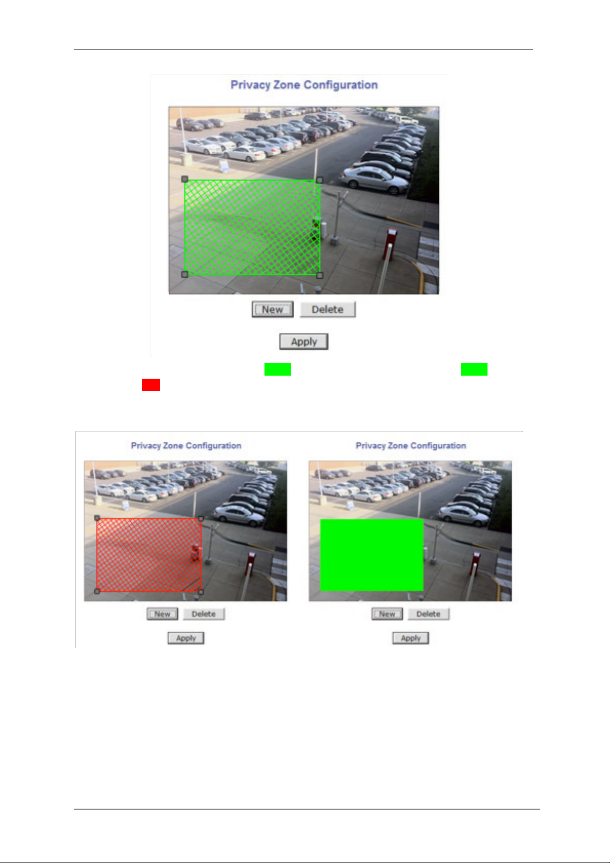
14.1. Privacy Zone
Users can set a privacy zone if a certain part of the screen needs to be unmonitored.
To set the region, click Privacy Zone from Device Config ura tion category.
49
Page 51
ENVI Series: VTC-IR40-N
To Add a Privacy zone click Newbutton, aGreen-colored box will appear, click on the Green box
and it will turn Red, at this point you can resize it by clicking and holding any corner and drag to
desired size. To relocate box click and hold anywhere inside the box and drag to desired location.
Click Apply when done
50
Page 52

ENVI Series: VTC-IR40-N
Users can add up to 8 Privacy Zones per screen by repeating above steps. If you add more than 8,
an error message will display on the screen.
To delete a privacy zone, click the zone and click Delete button followed by Apply button.
51
Page 53

ENVI Series: VTC-IR40-N
14.2. Camera & Motion
This menu is used to set up the selection of video format, data added to video data, encoding
speed, audio control, image res ol ut i on, video quality, motion detection, etc.
Click Camera & Motion on Device Con fi g ur a ti on menu. The configuration menu will be
displayed, and it may be different between VITEKcameras.
• M-JPEG: This format requires much higher network bandwidth than H.264 compression. But
because of its higher quality of still image, it is ade q uate for detailed reviewing of stored video.
• H.264: In this format, each frame data is related to other nearby frames. For this reason, it
provides much higher compression ratio than M-JPEG and is adequate for video transfer.
However, if network conditions are limited dropped frames in video data is possible, the video
quality can be relatively low. With VITEKCameras, you can set the number of P-frames in the
video which is independent still images between I-frames.
Note: For Dual Stream products, most of the parameters are dependent on primary
stream value.
You can configure the video data format and other informati on to be contained in it.
52
Page 54

ENVI Series: VTC-IR40-N
• Video with Flexible Extra System data: If Enabled, video data will contain UART sensor
(
data from COM port..
• Video with user defined message: If Enabled, video data will contain the user-defined
data. (Reserved Field).
• Video with PPP status: If Enabled, video data will contain PPP connection status..
available on this model)
• Video with camera name: If Enabled, video data will contain the camera name..
available on this model)
• Video with server name: If Enabled, video data will contain the server name that you
(
defined..
• Video with IP address: If Enabled, video data will contain the IP address of the video
server..
• Audio: (not available on all models) Select if Audio function is to be used (applies to Prim ary
Stream only). VITEK Cameras provides 2-way audio st reaming by combining microphone input
with video data. Users can listen to the streamed audio through a PC and speakers.
• Frame Rate: For Primary Stream, this is the number of frames compressed in every second.
You can control the network traffic with this parameter. For Secondary Stream, it can be set to a
manner of 1/2, 1/4, 1/8... of the p rimary stream.
• Image Size: Select the resolution of each channel’s video
• Encoding Standard: Select the compression method of each video, either M-JPEG or H.264
format. It is not allowed to set both channels to M-JPEG.
Below is the table of images sizes. To save the setting, click Apply button
Feature not available on this model)
(
Feature not available on this model)
Feature not available on this model)
(
Feature not available on this model)
(
Feature not
(
Feature not
Video Format SXGA D1 CIF QCIF
53
Page 55

ENVI Series: VTC-IR40-N
Rate Control Mode: CBR (Constant Bit
NTSC - 704 x 480 352 x 240 160 x 112
PAL - 704 x 576 352 x 288 160 x 144
VGA - 640 x 480 320 x 240 160 x 112
1.3M Pixel 1280 x 1024 640 x 480 320 x 240 160 x 112
2.0M Pixel 1920 x 1080 640 x 480 320 x 240 160 x 112
14.3. Camera Configuration
On the lower part of Camera & Motion Configuration menu, select a channel to configure.
In the example shown below, Primary Stream is set to H.264 for compression format.Enter
detailed parameters of the camera selected here.
• Camera Name: Enter the name of the channel up to 21 alphanumeric or up to 10 Unicode
characters.
Rate Control Mode:VBR (Variable Bit Rate)
Video frames are encoded with selected
image quality and GOP. Encoded frames have
different data size from each other.
H.264
Rate)
Video frames are encoded with selected
image quality and GOP.Encoded frames have
the same data size as other frames. Due to
the constant bit rate, ithas better stable
transmission performance.
M-JPEG -
54
Primary Stream of (H.264)
Image Quality:one of 6 quality levels
(Low Compression / Highest /High
Normal / Low / Lowest)
GOP Structure: Distance between IFrames. That is filled with P-frames.
Bit Rate Control: Total number of Bits
encoded per second. The higher Bit
Rate, the better image quality. Can be
set between 32kbps and 2Mbps.
GOP: Distance between I-Frames. That
is filled with P-frames.
Image Quality: one of 6 quality levels
(Low Compression / Highest / High
Normal / Low / Lowest)
Page 56

ENVI Series: VTC-IR40-N
14.3.1. Rate Control Mode
14.3.2. Image Quality Setup
In Image Quality level setup, select “Low Compression” for higher image quality, but it requires
higher network bandwidth. Selecting the “Lowest” requires lower network bandwidth, but gives
decreased image quality.
After configuration is finished, click Apply button to save the setting. If you click Default button,
the entire configuration will be reset to the original values.
Motion Detection
• Motion Detection:(this is only available in Primary Stream) If enable d, Motion Detection
feature is activated and user can configure the areas where motion detection function will work.
Click Check All button for whole scene to be active (grid will turn Green) then click on any box
inside scene to take out that area from Motion Detection (box will turn Red) then clickApply to
save
• Motion Sensitivity: Set the sensitivity of motion defined in Motion Detection Area. Select
between -100 and 100. 100 is the most sensitive.
After all the settingsare done, click Apply button to save it. If Default button is clicked, all the
fields return back to original value.
14.4. Camera Contr o l (S elect Models) Select Camera Control on the bottom of Camera & Motion Conf iguration menu.
55
Page 57

ENVI Series: VTC-IR40-N
Exposure
AGC (Automatic Gain Control)
You can adjust the AGC manually
56
Page 58

ENVI Series: VTC-IR40-N
SENS –UP
Allows color video in low light environment without noise (static).
Levels of adjustment (x2, 4, 6, 8, 10, 15, 20,30)
If set to high ghosting may appear
Brightness
D-WDR
You can select (OFF, Low, Middle, High)
57
Page 59

ENVI Series: VTC-IR40-N
DEFOG
Enhances image in foggy weather. (The performance is very limited)
You can select (OFF, Low, Middle, High)
BACKLIGHT>>
BLC
GAIN
Adjusts the amplification of the video through Low, M i ddle and High levels
58
Page 60

ENVI Series: VTC-IR40-N
AREA
To adjust the Area where “BLC” is relevant.
Position
Position the shaded area by using UP/DOWN/ LEFT/RIGHT arrows, then click
ENTER
SIZE
Change the Size using UP/DOWN/LEFT/ RIGHT arrows, then click ENTER
59
Page 61

ENVI Series: VTC-IR40-N
RET
Return to Exposure Menu or select arrow right to AGAIN to redo area.
DEFAULT
Default the settings from BLC
Return
Return to the Exposure screen
60
Page 62

ENVI Series: VTC-IR40-N
BACKLIGHT >>
This function is to prevent against the intense light from washing out the picture,
such as headlights from a vehicle.
HSBLC
SELECT AREA 1
You can select area 1 thru 4 by clicking ri ght or left button.
WINDOW
After selecting Area, select window on
61
Page 63

ENVI Series: VTC-IR40-N
POSITION
Using the UP / Down / Left / Right position the area where needed, then click
ENTER
Size
Using the UP / Down / Left / Right position the size needed then click ENTER
62
Page 64

ENVI Series: VTC-IR40-N
RET
Return to Exposure Menu or select arrow right to AGAIN to redo area.
LEVEL
Adjust the intensity level of the highlight masking
63
Page 65

Mode
Day or Night for highlight ma sking
ENVI Series: VTC-IR40-N
BLACK MASK
Turns masking ON and OFF
DEFAULT
64
Page 66

ENVI Series: VTC-IR40-N
Defaults HSBLC selection
RETURN
Return to EXPOSURE screen
RETURN
Return to SETUP screen
LENS>>
This camera is equipped with an A uto Iris Lens “DC” for the automatic
adjustment of lighting conditions.
DC
65
Page 67

MODE
Adjust mode to the proper application (indoor / outdoor)
RETURN
ENVI Series: VTC-IR40-N
Return to SETUP screen
LENS>>
MANUAL
FUNCTION NOT AVAILABLE
FOCUS ADJ.
Adjusts the focus between day and night
66
Page 68

ENVI Series: VTC-IR40-N
D/N DWELL
Adjust the time between day and ni ght when POP on CVBS is turned on
POP ON CVBS
Start sequencing between day and night images for focusing
RETURN
Return to SETUP screen
DAY & NIGHT
DAY&NIGHT menu can be set to AUTO, COLOR, B/W or EXT.
67
Page 69

ENVI Series: VTC-IR40-N
In AUTO, camera determines DAY or NIGHT by the incoming light level through
the lens only and IR CUT FILTER switches fol lowing the DAY/NIGHT modes.
In COLOR, camera disables DAY/NIGHT feature and works as a regular color
camera and IR CUT FILTERis inserted to cut out the infrared spectrum from the
light.
In B/W, camera disables DAY/NIGHT feat u re and works as a regular B/W camera
and IR CUT FILTER is removed to pass the infrared spectrum from the light.
In EXT, camera follows the decision for DAY or NIGHT by the light sensor built
into the camera.
Note: A camera with IR Led’s must be set to EXT.
IR SMART
Compensates the amount of IR light on an image, reflecting back to the lens.
AREA
To adjust the Area where the IR intensity is too high.
68
Page 70

ENVI Series: VTC-IR40-N
NR(Noise Reduction)
2D&3DNR are very sophisticated and powerful noise reduction technologies at low light.
2DNR
The process of removing image noise from a video signal by applying a digital
comb filter
3DNR A 3D filter reduces the noise caused by movement resulting in less blur.
Too strong 3DNR reduction results in the tail effect of a comet or motion blur forma fast moving
target in low light.
The process of removing image noise from a video signal by applying a digital comb filter
69
Page 71

ENVI Series: VTC-IR40-N
2DNR. ON reduces the noise that can be found in lo w light images
3DNR ON Reduces the no ise caused by movement. Start / End of noise reduction
with respect to light level can be set to required levels
START THRES sets the point from which 3DNR levels starts when the illumination
level dims. Higher setting starts3DNRat higher light level.
END THRES sets the point from which 3DNR stops when the illumination level is
higher.
DEPTH sets the strength of noise reduction for 2D&3D. A higher setting stands for stronger
reduction, too high of a setting will result in loss of sharpness in 2DNR and ghosting effect in 3DNR.
70
Page 72

ENVI Series: VTC-IR40-N
SMART NR continuously monitors motion on the screen.When no motion is detected, 3DNR is
automatically activated for the maximum reduction of noise at low light. 3DNR becomes
immediately deactivated upon motion. This will save HDD space
PICT ADJUST (Picture Adjustment)
InPICT ADJUST menu, WHITE BAL, SHARPNESS, MONITOR, OSD COLOR, CORNER COMP
andD-EFFECT can be set.
ATW - Automatic Tracking White balance
AWC – White Balance is set at a fix leveland stops even though the color temperature changes.
INDOOR – White Balance is fixed at around 3100K.
OUTDOOR - White Balance is fixed ataround 5100K.
MANUAL - Adjust White Balance with fixed values of BLUE and RED.
71
Page 73

ENVI Series: VTC-IR40-N
SHARPNESS
Increases or decreases the sharpness of the picture.Too much sharpness makes the image harsh
and shows more noise and line flicker at the edge of objects in the picture.
MONITOR
Sets LCD or CRT.
LCD:
GAMMA, BLUE, GAIN or RED GAIN is adjustable for the best view with LCD
monitor. Low GAMMA compensates for dark are as, slightly but contrast becomes
low. High GAMMA increases contrast but looses the visibility of dark areas.
CRT
: BLACK LEVEL, BLUE GAIN or RED GAIN are adjustable.
72
Page 74

ENVI Series: VTC-IR40-N
OSD
TEXT COLOR - Can be change to 1 of 8 colors. Selected color is applied to menu text and
cameratitle.
OUTLINE – Makes the letters bold
BACK TABLE - Is the color bar where the cursor is located
CORNER COMP
Enhances brightness of the corners caused by the lens, or the narrow angle of IR LEDs. Picture
could be noisy when ON.
D-EFECT
FREEZE: Freezes Image
73
Page 75

ENVI Series: VTC-IR40-N
MIRROR:OFF(normal display), MIRROR(Left & right mirrored), V-FLIP(upside down) and
ROTATE(H/V-FLIP)
D-Zoom
(Function not available)
NEG.IMAGE: If set to ON,.
SPECIAL
In SPECIAL menu, CAM TITLE, MOTION, PRIVACY, LANGUAGE, PIXEL COM and
TV SYSTEM can be set.
74
Page 76

ENVI Series: VTC-IR40-N
CAM TITLE: OFF / ON. When on click ENTER
Up to 15 characters can be use on camera title line, use ▲,▼,◀,▶ to navigate around chart, when
letter or character is flashing click ENTER, continue this in till completed. When done arrow over to
POS (POSITION), click ENTER and position camera title to desire location, click enter to return to
previous screen and arrow over to END and click ENTER.
MOTION
Note USE Moti on Detection Settings under Device
Configuration
PRIVACY
75
Page 77

ENVI Series: VTC-IR40-N
Note USE Privacy settings under Devi ce Configuration
LANGUAGE
English, Japanese, Chinese 1, Chinese 2, German, French, Italian, Spanish and
Polish.
PIXEL COMPENSATION
Sometimes image sensors have defective pixels, this can be compensated in
two different ways LIVE DPC, compensates the defective pixels in real time and STATIC
DPC, detects the defective pixels with lens closed and saves the data for compensation
LIVE DPC compensates the defective pixels in real time where pixelamplitude
exceeds the thresho l d.
AUTO - Enables LIVE DPC and dynamically compensates the defective pixels
whose amplitude exceeds the threshold calculated according to AGC. At low light,
more defective pixels are compensated because the thresh old becomes lower due
to high AGC.
76
Page 78

ENVI Series: VTC-IR40-N
ON - Enables LIVE DPC and compensates the defective pixels whose magnitude
exceeds the thresho l d by set level.
OFF - Disables LIVE DPC.
Note: High setting of LEVEL in LIVE DPC reduces the sharpness
STATIC DPC
Detects the defective pixels with lens closed and saves the data for compensation
ON -Enables the compensation for the detected defective pixels.
OFF - Will not apply the compensation.
DO STATIC
Camera closes the lens automatically and detects the defective pixels.
Note: Lens cap is highly recommended because the iris of some lens do not close perfectly.
After covering the lens click ENTE R then click ENTER on Execute screen
77
Page 79

ENVI Series: VTC-IR40-N
STATIC THR
For white dots (noise) caused by a defecti ve pixel exceeding the levels will be
compensated. The lower the setting the more pixels will be compensated up to 1024 staring from
top to bottom.
PIXEL BOOST
It is easier to detect defective pixels with PIXEL BOOST, but the higher the level the more noise
might be detected by mistake and give a false reading.
TV SYSTEM
Select between US (NTSC 60Hz) or EU (PAL 50Hz)
78
Page 80

ENVI Series: VTC-IR40-N
Factory
Defaults the camerasettin gs (Not the network settings)
EXIT
Exits the Set up menu
14.5. DI (Sensor Input) / DO (Alarm Output)
Select DI/DO from Device Configu ration menu to name and configure Sensor Input and Alarm
Output. After configuring, select DI Status/DO Control on Device Configuration menu to
manually control DO (Alarm Output) and check status of DI (Sensor Input).
DI/DO Setup DI/DO Control
79
Page 81

ENVI Series: VTC-IR40-N
DI/DO functionality can be set to either Normal Open or Normal Closed type as follows.
• Normal Open Type: Normal is OPEN, and goes CLOSED when triggered by an event.
• Normal Close Type: Normal is CLOSED, and goes OPEN when triggered by an event.
Note: Make sure the type of the sensor and use it correctly to the type. If a Sensor Input
is not used, it must be set to Normal Open Type t o avoid a false input.
80
Page 82

ENVI Series: VTC-IR40-N
15. Advanced Configuration
There are two types of advanced service, one is Buffered Service and the other is Periodic
Service. In Buffering Service, a series of images are continuouslybeing stored in a buffer memory
of thecamera/server for a certain period of time. When the camera/server is triggered by an event
or schedule, the images or alarm statusjust before and after the event/schedule are reported to
you by email or buffered FTP services.
In Periodic Service, only the image, alarm/sensor status after an event/schedule i s reported to you
upon the server being triggered.
81
Page 83

ENVI Series: VTC-IR40-N
15.1. Advanced Services
Pre-Alarm buffer size and buffering speed can be defined here.
• Pre-Alarm Buffer Size: You can set the buffer size which will store the images before event.
The unit is in frame, and each channel ca n be set with different values. The total number of
frames for Pre-Alarm Buffer and Post-Alarm Buffer is limited to 10 frames.
• Pre-Alarm Speed: You can set the buffering speed. If it’s set to Fastest, the server will store
images as fast as it can. Each cannel can be set with different values.
This configuration applies to E-mail and FTP(Buffered), and click Save button to apply changes.
• E-mail: Set up Email Service configuration
• FTP (Buffered): Set up FTP (Buffered) Service configuration
• FTP (Periodic): Set up FTP (Periodic) Service configuration
82
Page 84

ENVI Series: VTC-IR40-N
Item
Description
15.1.1. E-mail Service Configuration
Email configuration is set up here for Alarm in case any event occurs.
Camera 1~2 Select a channel to be configured for email notification
Service Select Enable in order to use this service
SMTP server address Enter SMTP server’s address for sending email.
Authentication Login Select Enable if SMTP serve r requires ID and password
User ID Enter User ID to log in to SMTP server
Password Enter Password to log in to SMTP server
Sender Enter email address of the sender
1st Recipient Enter the email address of the first recipient
2nd Recipient Enter the email address of the second recipient
3rd Recipient Enter the email address of the third recipient
Click Save button to apply the change. If you do n’t want to change, click Back button.
83
Page 85

ENVI Series: VTC-IR40-N
E-mail Service Setup for Each Channel
For each channel, the following items can be configured for email service: Condition, Post-Alarm
Buffer Size, and Post-Alarm speed. The content of text message and display style of DI value can
be configured as well.
Item Description
Condition 1 ~
Condition 3
Pre-Alarm Buffer Size The Buf fer siz e assigned for Pre-Alarm.
Check Video buffer Click this link to go to Advanced Services for buffer setup.
Pre-Alarm Images The number of image frames to store before Alarm
Post-Alarm Images The number of image frames to store after Alarm
Pre-Alarm Speed
Post-Alarm Speed Select the speed of Post-Alarm. Fastest is the highest value.
Subject Subject of the E-mail message to send.
1 Content of the first line in the email message.
2 Content of the second line in the email message.
3 Content of the third line in the email message.
4 Content of the fourth line in the email message
Value Format
Select a condition for Email service to be activated.
This field shows the speed of Pre-Alarm. Configuration can be
done in Advances Services pag e.
Select the format for the Event or DI data to email.
NONE: Don’t Send, INT: Decimal, HEX: Hexadecimal,
BIN: Binary, IPA: IP Address, EVT: Name of Event
84
Page 86

ENVI Series: VTC-IR40-N
Item
Description
After finishing setup, click Save button to apply. If you don’t want to change, click Back button.
Condition, Schedule & Event Configuration
If you click on a Condition link, the Advanced Service windows is displayed as shown below.
Alarm Service is activated only when the conditio ns in Advanced Services are met.
Service This shows what service this condition is for.
Module ID Module ID for current setup
Camera ID Channel ID for current setup
Enable / Disable Select Enable to use Condition, otherwise select Disable.
Always This Condition applies all the time. (Schedule or Event is not usable)
Schedule Only
Event Only
To save the setting, click Save button. If you want to cancel it, click Back.
Use Week, Time, and Date in Condition parameter. If none of the
weekdays arechecked, it is activated every day.
It is activated only when any of the following events occurs.
(Sensor, Motion Detection, Camera Connection, Server Booting)
85
Page 87

15.1.2. FTP (Buffered) Service Configuration
Item
Description
Enable
Server Address
FTP Server Address.
ENVI Series: VTC-IR40-N
Camera 1 - Camera
2
Service
Base Directory
Name
Base File Name The base file name of the data to be uploaded in FTP server.
86
Select which channel to set up for FTP (Buffered).
Select
Disable.
The directory in FTP server where the data will be uploaded.
(You should make the directory in the FTP server before using the
service.)
to use the FTP (Buffered) service. Otherwise select
Page 88

ENVI Series: VTC-IR40-N
Connection Mode
Select connection mode for FTP server
If File Name is checked, new file is created with server name.
Directory Name
If Directory Name is checked, new directory name is created with
Directory Name
If Directory Name is checked, new directory name is created with
Sequence
If checked, new files are created starting from 0, with increment of 1.
User ID Ent er a User ID to log in to FTP server.
Password Enter the Password for the user ID to log in to FTP server
FTP Control Port Port number for FTP server (Normally 21 is used)
Date Description
Mode
Server Name
Select Date Display Style:American, European or ISO Standard
If Directory Name is checked, new directory is created w ith server
name.
If
Weekday
Year
Month
Day
Hour
Minute If checked, new file name is created with minute.
Sec If checked, new file name is created with second.
Camera Number
To create a dire c tory with the options shown above, click Make Directory button. After finishing
the configuration, click Save button to apply the change and continue to the next page. Clicking
Back button will cancel the changes and go b ack to the previous page. (This service is available
only in M-JPEG mode.)
weekday.
If File Name is checked, new file name is created with weekday.
Year.
If File Name is checked, new file name is created with Year.
If Directory Name is checked, new directory name is created with
month.
If File Name is checked, new file name is created with month.
If
day.
If File Name is checked, new file name is created with day.
hour.
If File Name is checked, new file name is created with hour.
If Directory Name is checked, new directory is created with camera
number.
If File Name is checked, new file is created with camera number.
is checked, new directory name is created with
is checked, new directory name is created with
FTP (Buffered) Service Configuration at Camera 1
87
Page 89

Item Description
ENVI Series: VTC-IR40-N
Condition 1 ~
Condition 3
Pre-Alarm Buffer Size The Buffer size assigned for Pre-Alarm.
Check Video buffer Click this link to go to Advanced Services for video buffer setup.
Pre-Alarm Images The number of image frames to store before Alarm.
Post-Alarm Images The number of image frames to store after Alarm.
Pre-Alarm Speed
Post-Alarm Speed Select the speed of Post-Alarm. Fastest is the highest value.
After finishing setup, click Save button to apply. If you don’t want to change, click Back button.
15.1.3. FTP (Periodic) Service Configuration
Select a condition for FTP (Buffered) service to be activated. Up to 3
conditions can be set.
This field shows the speed of Pre-Alarm. Configuration can be done in
Advances Services page.
88
Page 90

ENVI Series: VTC-IR40-N
If File Name is checked, new file name is created with weekday.
Directory Name
If Directory Name is checked, new directory name is created with
Directory Name
If checked, new files are created starting from 0, with increment of
Item Description
Camera 1 - Camera 2 Select which channel to set up for FTP (Periodic) service
Service
Server Address FTP Server Address.
Base Directory Name
Base File Name The base file name of the data to be uploaded in FTP server.
User ID Enter a User ID to log in t o FTP server.
Password Enter the Password for the user ID to log in to FTP server
Sequence Modulo Maximum number used in sequential file name
FTP Control Port Port number for FTP server (Normally 21 is used)
Date Description
Mode
Connection Mode Select connection mode for FTP server
Select Enable to use the FTP (Periodic) service. Otherwise select
Disable.
The directory in FTP server where the data will be uploaded.
(You should make the directory in the FTP server before using the
service.)
Select Date Display Style: Amer ican, European or ISO Standard
Overwrite If checked, new file overwrites the existing file with the same name.
If Directory Name is checked, new directory is created w ith server
Server Name
Weekday
Year
Month
Day
Hour
Minute If checked, new file name is created with minute.
Sec If checked, new file name is created with second.
Sequence
Camera Number
To create a dire c tory with the options shown above, click Make Directory button. After finishing
the configuration, click Save button to apply the change and continue to the next page. Clicking
Back button will cancel the changes and go back to the previous page. (This service is available
only in M-JPEG mode.)
name.
If File Name is checked, new file is created with server name.
If Directory Name is checked, new directory name is created with
weekday.
If
year.
If File Name is checked, new file name is created with year.
month.
If File Name is checked, new file name is created with month.
If Directory Name is checked, new directory name is created with
day.
If File Name is checked, new file name is created with day.
If
hour.
If File Name is checked, new file name is created with hour.
1.
If Directory Name is checked, new directory is created with camera
number.
If File Name is checked, new file is created with camera number.
is checked, new directory name is created with
is checked, new directory name is created with
89
Page 91

FTP (Periodic) Service Configuration for each channel
Item
Description
Select a condition for FTP (Periodic) service to be activated. Up to 3
ENVI Series: VTC-IR40-N
Condition 1 ~ Condition 3
FTP interval (msec) Select the speed of images to send in FTP(Pe r iodic) service
After finishing setup, click Save button to apply. If you don’t want to change, click Back button.
conditions can be set respectively.
16. Recording Configuration for Cameras with S D card
Some versions of VITEK IP cameras will have a microSD or a full SD Card.
Those models can record and playback video from the SD card ifinstalled.Vitek IP cameras
canSupport cards up to a 32GB. (Only use quality class 10 SD cards)
16.1. SD/ MicroSDCard Configuration
If a SD card is not present in the slot already, power down the VITEK IP camera
before inserting an SD card. Make sure to turn the power on after inserting the SD card. Open a
webbrowser, type in the IP address of the VITEK camera. Log in as Admin, Enter Recording
Configuration menu, and the n click onSD Configuration then click on SD Information, the
card’s format information will be displayed
90
Page 92

ENVI Series: VTC-IR40-N
If entire SD information is showing “-NONE-” this means SD card is not formatted, in this case click
Note: Be sure to turn off the device before installing a SD card. Otherwise, the SD card
may become defective. Always check the recommended type of SD card because
non-conforming SD cards can cause abnormal behavior of the system.
back button followed by clicking SD Status & Format
Click on “1
st
SD” and the following screen will be displayed
Read format option on screen and then click Partition and Formata pop up screen will display
asking if you want to do a “Partition and formatting” click OK to continue or Cancel to stop. After
clicking OK the following screen will be displayed
91
Page 93

ENVI Series: VTC-IR40-N
Note: if program is terminated during the “Format” process SD Card might be damaged
After formatting is completed the following screen will be displayed
Click OK and you will be brought back to the “SD Status & Format screen” click on “Reb oot ”
wait approximately 30 seconds and log b ack into the Admin screen. Open up “Recording
Configuration” menu and click on “SD Co nf iguration” then cli c k on “SD Information” and the
following screen will be displayed showing SD card info
92
Page 94

ENVI Series: VTC-IR40-N
16.2. Recording Configuration with SD card
Each camera has 2 streams (referred as Camera 1 / Camera 2 (see image below)) which can be
configured for recording options in this section. Configuration items include motion detection
recording, 24-hour continuous recording, event-driven recor ding, etc.
You can find out the list of streams (camera 1 / camera 2) with recording capability by clicking
Recording Config ur ation on the left side of your screen. For example, you will see 2streams
(camera 1 / camera 2) from the list of VS Module ID (IP Devices).
Below is an example of configuring the motion detection-triggered recording. It starts by clicking
Recording Configuration and clicking on Camera1,
the following screen will be display.
93
Page 95

ENVI Series: VTC-IR40-N
Select Condition 1andthe following window will be display.
Enable / Disable
94
Page 96

ENVI Series: VTC-IR40-N
By clicking on Enable you will be able to select your mode (Always, Schedule only etc). in this
example we will be selecting “Event Only”.
Schedule
Under Scheduleyou can select time and date for motion recording if left blank motion recording
will be 24hrs, 7 days a week. In this example we will be leaving it blank (24/7).
Event
Under Event click
Motion Detection
(stream 1 / stream 2). Click on Save to finish.
17. Utilities
In Utilities part of the Admin menu, you can view the System Log file, Save Configuration,
Reboot, FactoryDefault and System Update.
95
Page 97

ENVI Series: VTC-IR40-N
17.1. System Log
System log file provides you the information about when and who access’ the contents of
VITEKCameras such as HTTP file or CGI programs. In each line, log data consists of date, tim e,
category, IP address, user ID.
17.2. Save Configuration
VITEK cameras save the configurations afte r every step.
96
Page 98
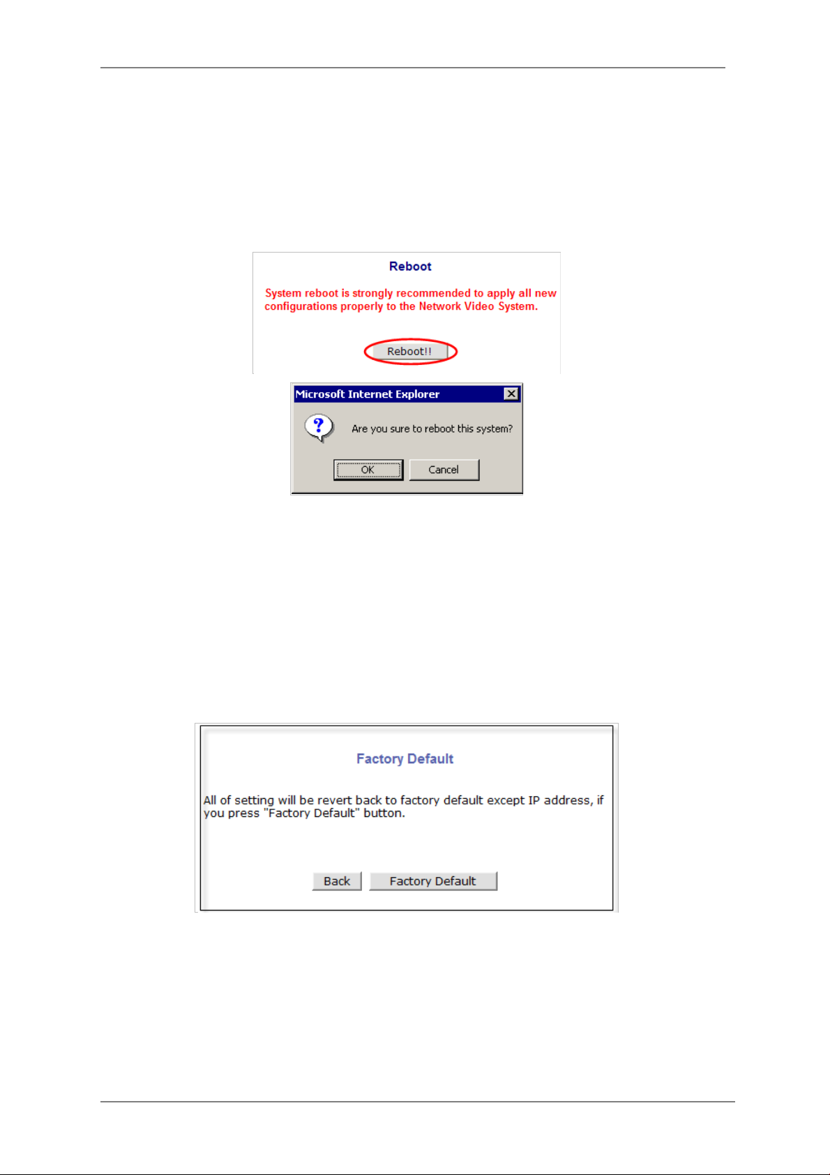
ENVI Series: VTC-IR40-N
17.3. Reboot
It is recommended to reboot the system after making changes to the configuration. To re boot,
click Reboot on Utilities menu. A screen will display to confirm a system reboot , click ok to
continue.
Windows Internet Explorer will ask to close the webpage, click Yes.
17.4. Factory Default
When required to restore the configur ation of a Camera to factory default conditions,Network
configuration is not affected by this action.
Click Factory Default on Utilities menu. A confirmation screen will be displayed as shown Click
Factory Default button, otherwise click Back button to cancel it. The second confirmation screen
will appear. Click OK button to restore the factory default condition right away. If you click Cancel,
web browser will go back to the previous screen without any change made.
97
Page 99

ENVI Series: VTC-IR40-N
17.5. System Update ** Is Highly Recommended to Use the IP Installer Program for This Process **
Once IP devices are searched and shown on the screen as functioning successfully, you can update
the firmware of them using the“IP Installer” program. To do t hat, first check the firmware version
of the device, which you can find on the IP Installe r window.
98
Page 100

ENVI Series: VTC-IR40-N
In the above picture, the firmware version of this product is 4.14-01-ds while the latest
firmware version available is 4.16-B0-ds-VI as you can see at Vitek’s homepage
(
http://www.vitekcctv.com/Downloads.asp). If you decide to update the firmware, first
create a folder on your computer for the update firmware, than download the latest firmware to
that folder.
Then select the IP device to be updated on IP Installer window, then click Update Firmware
button from the toolbar. The following window will be displayed.
You may find the Password field is empty on the window shown above. If so, click the Password
field of the IP device and enter the proper password for the device. You are not allowed to update
the firmware if the correct password is not provided.
After the password is entered, the Start Update button will be enabled now. Click the button to
see the following window for selecting the folder where the file has been saved.
folder than click
After clicking OK the following window will be displayed.
OK.
Highlight the
99
 Loading...