

Page 1
VITEK
VTC-C770WDR
WDR True Day and Night
(ICR) Camera
• Pixim D8800C Seawolf Digital Imaging System CMOS
• 700TVL High Resolution
• On Screen Display (OSD) Menu
• 3DNR - Three Dimensional Motion Adaptive Noise Reduction
• UTC CONTROL - Serial Control over Coax
• 0.00008 Lux (F1.2@40IRE using sense-up)
• Supports C/CS mount DC drive lenses
• Supports NTSC & PAL Standards
• 4:3 / 16:9 Ratio Scaled Video Output
• CRT / LCD Selectable Video Output Optimization
• 10 - bit ITU DSP
• 4 Metering Zones for WDR Optimization
Page 2
VTC-C770WDR
1
To prevent fire or shock hazard, do not expose the unit to rain or moisture.
The symbol is intended to alert the user to the presence of important
operating and maintenance (servicing) instructions in the literature
accompanying the unit.
The symbol is intended to alert the user to the presence of un-insulated
"dangerous voltage" within the product's enclosure that may be of sufficient
magnitude to constitute a risk of electric shock to person.
Warning (NTSC version) -- This equipment has been tested and found to comply with the limits for a Class
A digital device, pursuant to part 15 of the FCC Rules. These limits are designed to provide reasonable
protection against harmful interference when the equipment is operated in a commercial environment. This
equipment generates, uses, and can radiate radio frequency energy and, if not installed and used in
accordance with the instruction manual, may cause harmful interference to radio communications.
Operation of this equipment in a residential area is likely to cause harmful interference in which case the
user will be required to correct the interference at their own expense.
Caution -- Any changes or modifications in construction of this device that are not expressly
approved by the party responsible for compliance, could void the user's authority to operate the
equipment.
WARNING
Caution
To prevent electric shocks
and risk of fire hazards, do
NOT use other than specific
power source.
Page 3

VTC-C770WDR
2
Table of contents
1. Safety Instructions and Notes….......................................................................................................
2. General Descriptions............................................................................……………………………...
3. Supplied Items......................................................................................……………………………...
4. Part names…………………………….…...................................................…………………………...
5. Installation and commissioning Instructions....................................................……………………...
6. Start up…………………............................................................................…………………………...
7. Setup Menu……………………………………………….....................................................................
8. Specifications…………………………………………….....................................................................
9. Dimensional Drawings…................................................................................................................
3
3
4
5
6
7
8
17
18
Page 4

VTC-C770WDR
3
1. Safety Instructions and Notes
• Read instructions carefully before putting the camera into operation.
• Keep the operating instructions in a safe place for later use.
• The Standard Box Camera is designed for indoor use only and it must not be installed where exposed to
rain and moisture.
• Do not operate the cameras beyond their specified temperature, humidity or power ratings.
• Never open the case of the camera because there are precision parts inside. An accident may
result.
• Do not put anything metallic or foreign through the vent. A fire or electric shock may result.
• Be sure to turn off the power before installing or making connection.
• Pay attention when laying the connection cable and observe that the cable is not subject to heavy loads,
kinks or damage and no moisture can get in.
• Do not install the camera in places exposed to vibrations and shocks.
• Be very careful not to drop or shock the camera while carrying it.
• Do not angle the camera to the sun.
• Do not make any modification to the unit (neither to the software nor the hardware). Improper modification
voids the warranty and can cause malfunctions or damages. The manufacturer accepts no liability for
damages resulting from unauthorized or improper modifications to the unit.
• Some types of lenses may cause hunting, light amount drop or other problems. In such case, readjust the
lenses.
• Because of the digital image device characteristics, images may look rugged at high temperatures. This
does not mean the camera is in trouble.
• The warranty becomes void if repairs are attempted by unauthorized persons.
• Contact the supplier if any functional problems arise.
Cleaning:
• Do not touch the surface of the imaging device.
• Keep front and rear lens surfaces clean.
Notice -- The images used in this manual are processed to help comprehension and may differ from
actual video of the camera.
2. General Descriptions
VTC-C770WDR (VTC-C770WDR/PAL for PAL)) is a superb wide dynamic range camera which
achieves 120dB max (102dB typical) dynamic range of the image by implementing PIXIM's Seawolf
digital imaging system.
With Seawolf digital imaging system:
- Delivers high-resolution, crystal clear images that accurately capture every aspect of any scene
- Offers the highest resolution of 700TVL (horizontal)
- Ultra-wide dynamic range imaging accurately captures all of the critical details in a scene including
highlights, shadows and everything in between without compromising image quality or color
accuracy
- Enhanced low-light performance makes Seawolf the natural choices for both indoor and outdoor
cameras for all lighting conditions
With ICR mechanism:
- Enhances its sensitivity about 10x at night time
- Accepts infrared light
Page 5

VTC-C770WDR
4
With 24VAC/12VDC dual power design:
- Offers flexibility of installation
- Ensures reliability
Main features are;
• Pixim D8800C Seawolf Digital Imaging System CMOS
• 700TVL High Resolution
• On Screen Display (OSD) Menu
• 3DNR - Three Dimensional Motion Adaptive Noise Reduction
• UTC CONTROL - Serial Control over Coax
• 0.00008 Lux (F1.2@40IRE using sense-up)
• Supports C/CS mount DC drive lenses
• Supports NTSC & PAL Standards
• 4:3 / 16:9 Ratio Scaled Video Output
• CRT / LCD Selectable Video Output Optimization
• 10 - bit ITU DSP
• 4 Metering Zones for WDR Optimization
3. Supplied Items
1 x WDR TDN Color Camera
1 x Dust protection cap
1 x Installation and Operating Instructions
Page 6
VTC-C770WDR
5
3
1
2
4
5
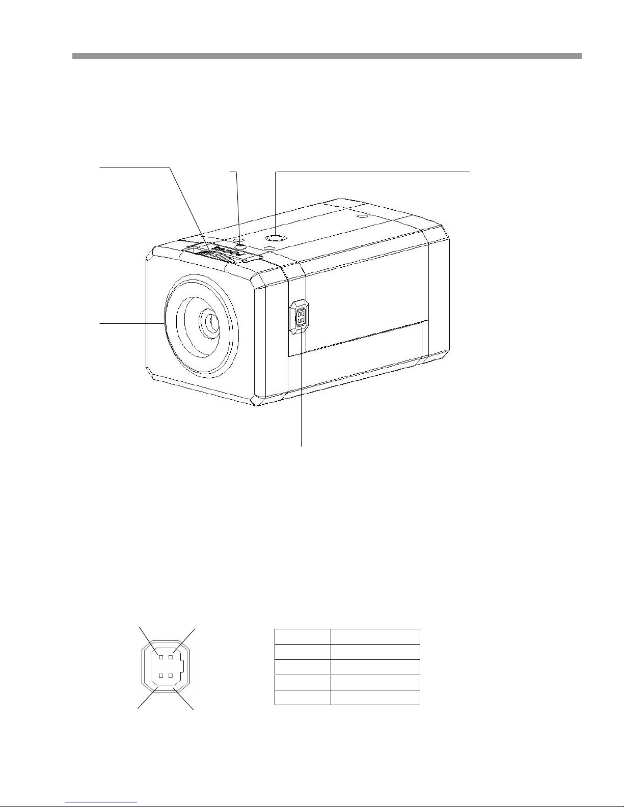
4. Part Names
4.1 Front view
- Lens Connector for Auto-iris lens (DC Drive)
① Back Focus Adjustment ② Dust Protection Cap
③ Lens connector for auto iris lenses ④ Back focus Adjustment Lock Screw
⑤ Camera Mount Hole (Top and Bottom)
PIN No
DC Iris
1
Damp(-)
2
Damp(+)
3
Drive(+)
4
GND
PIN 4 PIN 2
PIN 3 PIN 1
Page 7
VTC-C770WDR
6
ⓐ
ⓑ ⓒ ⓓ
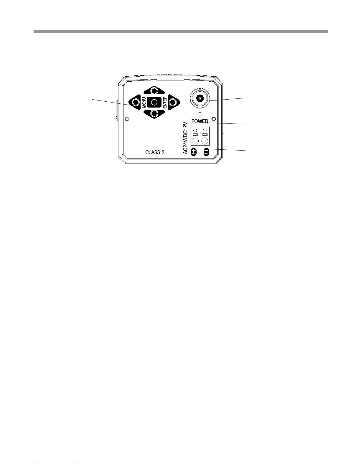
4.2 Rear side view
5. Installation and commissioning Instructions
• Make sure the power is removed before the installation.
• To apply power:
First connect the low voltage (DC12V or AC24V). Then plug the AC adapter to AC outlets to avoid an
improper reset from power jitters and damage from the surge voltage when no load.
5.1. Attaching the lens
• Remove the Dust Protection cap from the lens mount
• Screw the lens onto the camera without using force
5.2. Setting the back focus lock
The back focus is the distance between the lens support on the camera and the image sensor. Optimum
focus is only possible when the correct distance is set. It may be necessary to set the back focus in
individual cases due to production tolerances of the lens. The iris of the lens must be open as wide as
possible. (Smallest F value) to set the back focus. For lenses with automatic iris control, you will require a
ND filter (gray filter) to prevent the iris from closing in bright light.
Setting for lenses with a fixed focal distance:
If the focus cannot be set exactly by turning the focus ring (lens), please proceed as follows;
1. Point the camera at an object with sufficient contrast. The distance to the object should be longer than
1,000 x the focal distance.
2. Open the iris on the lens
3. Set the focus of lens so that the distance at the lens is close to infinity but not to exact infinity position.
4. Loosen Back focus Adjustment Lock: Screw one~two turns on the camera with industrial “+” driver
ⓐ OSD menu switches (Up/ Down/ Left/ Right / Enter)
ⓑ Video Output Connector (BNC)
ⓒ Power indicator LED
ⓓ Power Input Terminal
Page 8
VTC-C770WDR
7
5. Rotate Back Focus Adjustment until the optimum focus is achieved.
6. Tighten Back focus Adjustment Lock Screw again.
7. Trim the focus precisely at lens if necessary.
Setting for lenses with a variable focal distance (zoom):
If the focus changes as the focal distance changes, please proceed as follows.
1. Point the camera at an object with sufficient contrast at a distance of approximately 2 meters
2. Open the iris on the lens
3. Set the maximum focal distance (Tele) at the lens
4. Set the optimum focus with the focus ring
5. Set the smallest focal distance (wide angle)
6. Loosen Back focus Adjustment Lock. Screw one~two turns on the camera with the industrial “+” driver
7. Adjust Back Focus Adjustment until the optimum focus is achieved. Steps 3,4,5 and 7 may need to be
repeated several times to obtain the best results
8. Tighten Back focus Adjustment Lock Screw again
5.3. Installation
The camera has a 1/4” thread insert on its top and bottom side for mounting the camera to a tripod, wall
or ceiling with a corresponding mount.
5.4 Commissioning
• First, connect the power supply to the power terminal on the rear panel of camera
• Second, plug the power adaptor to the main supply
• ⓒ Power indicator LED will be lit
• The camera is ready for operation
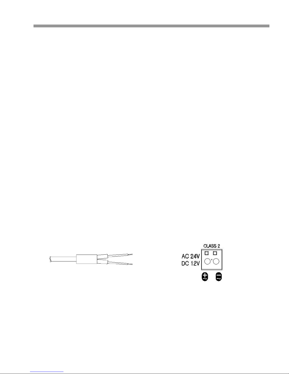
5.5. Power Supply Connections
The camera can work with either 24VAC or 12VDC, dual voltage power. It does NOT require the
polarity-matched connection for 12VDC supply. Primary and secondary grounds are completely
isolated to avoid the possible ground-loop problems. Its wide operating voltage range of 10.5V-30V
for DC and 12-28.8V for AC gives extra flexibility at the installation.
6. Start up
When the camera is powered properly, it starts up by initializing the internal parameters and the
filter switch mechanism. The filter switch unit repeats IN and OUT at each power up and just
after RESTORE FACTORY SETTINGS.
Page 9

VTC-C770WDR
8
7. SETUP
7.1 In the menu
Use , buttons to move the menu, , buttons to change the settings and press
button to select or enter.
button stands for MENU or ENTER button.
7.2 Entering menu
Press button longer for than 2 seconds on the back of the camera.
7.3 MAIN
Follow the chart below for submenu settings
MENU
Default
Descriptions
EXPOSURE
Sets COLOR ROLL COMP., AE PREFERENCE, WDR CONTROL and
SENSE-UP.
DAY/NIGHT
AUTO
Sets OFF, AUTO or NIGHT
OFF – Day/Night is disabled and camera works as a normal color
camera.
AUTO – Camera switches DAY from/to NIGHT automatically.
N->D THRES, N<->D DELAY, BURST ON B/W can be set.
See DAY&NIGHT AUTO SETUP for detail.
NIGHT – Forced to remove IR cut filter and switch to B/W.
3D NR
Sets DEPTH of 3D NR.
LENS
SELELT
DC
Selects the lens type, DC or MANUAL.
In sub-menu, Accurate Focus can be set by function of FOCUS
ADJ…
PICTURE
CONTROL
Sets WHITE BALANCE, COLOR SELECT, SHARPNESS,
SATURATION, GAMMA.
SPECIAL
Sets MOTION, PRIVACY MASK, SYNC, LANGUAGE, VIDEO
STANDARD, RS485 CONTROL.
D-EFFECT
Sets FREEZE, FLIP or D-PTZ.
EXIT
Choose EXIT, SAVE AND EXIT or FACTORY SET.
Page 10

VTC-C770WDR
9
7.4 EXPOSURE
To enter EXPOSURE menu, press button at MAIN>EXPOSURE.
EXPOSURE
Descriptions
<WDR MID>
Medium level of the dynamic range control for each PRESETs.
WDR HIGH
Increases the dynamic range control. Some highlight area may
washed out.
CUSTOM...
Provides more flexible compensation other than WDR MID, WDR
LOW, WDR HIGH
Compensates the brightness of main object against the bright
back light.
A zone out of CTR SPOT, UPPER1/3, MIDDLE1/3, LOWER1/3
EXPOSURE
Default
Descriptions
COLOR
ROLL
COMP.
OFF
In NTSC system, the entire color tone on the monitor may continuously
show reddish and greenish.
COLOR ROLL COMP. - Reduces the color rolling under the fluorescent
lighting. (NTSC system only)
OFF – Does not compensate the color rolling.
MODE-M - Compensates the color rolling when a manual lens is used.
MODE-A - Compensates the color rolling when an auto iris lens is
used.
AE
PREFRENCE
HIGHLIGHTS
Sets HIGHLIGHTS or SHADOWS
HIGHLIGHTS - Provides the best detail in the brighter areas. The
darker
parts of the scene may under-expose.
SHADOWS - Provides the best detail in the darker areas. It will reduce
the dynamic range and the brighter parts may overexpose.
WDR
CONTROL
MEDIUM
LOW - Produces an image that has better contrast but less dynamic
range and is suitable for indoor or low-contrast outdoor scenes.
NORMAL - Produces an image that has average contrast and is
suitable for indoor or low-contrast outdoor scenes.
MEDIUM - Produces an image that has better dynamic range and is
suitable for a lobby or high-contrast outdoor scenes.
HIGH - Produces an image that has best dynamic range but less
contrast and is suitable for high-contrast outdoor scenes.
CUSTOM - Provides more flexible compensation by ZONE, RANGE
and BIAS.
**When COLOR ROLLCOMP. is set to MODE-A, WDR CONTROL will
be fixed as LOW.
SENSE-UP
AUTO
If SENSE-UP is set to AUTO, the maximum sense-up rate can be
limited to 2X-30FPS, 4X15FPS, 8X-18FPS, 16X-4FPS, 32X-2FPS or
64X-2FPS in SENSE-UP SETUP.
The integration frames vary automatically within the max. rate
according to the light level when light becomes low and DSS is
operating. The higher sense-up rate, the higher sensitivity but the
slower refresh rate. Some white dots may appear by sense-up due to
the image sensor’s long accumulation by a long shutter period.
Page 11

VTC-C770WDR
10
7.5 DAY/NIGHT
To enter EXPOSURE menu, press button at MAIN>DAY/NIGHT>AUTO...
IMPORTANT!!!
DAY->NIGHT and NIGHT->DAY operations must be examined and verified at the final step
of the installation.
Block the lens for a few seconds for NIGHT mode and release and let it return to DAY mode.
If camera stays at NIGHT mode more than 10 seconds, increase N-->D THRES a little and
repeat the fore-mentioned steps. If the scene is too dim or lens iris was adjusted too low (near
close), it may not return to DAY.
DAY/NIGHT
Default
Descriptions
N-->D
THRES.
3
N-->D THRES is a threshold level to switch from NIGHT to DAY.
Due to the nature of WDR the image level of the scene is controlled down
and the camera will not switch to DAY despite bright ambience.
Increase the value if it stays in B/W and is required to switch to DAY.
Too high of a value may make ICR repeat between NIGHT<-->DAY.
In that case, slightly reduce the value and try all of the above.
N<-->D
DELAY
3
N<-->D DELAY is time in seconds while the camera maintains its status before
D<-->N switches.
DELAY can avoid the unwanted/frivolous switching by a short term light.
(I.e. the light from the passing car)
BURST
ON
B/W
OFF
BURST ON B/W determines whether a color burst signal keeps output or
eliminated when camera switches to B/W.
If set to ON, B/W video signal contains color burst signal and is more
compatible with the color equipment but shows the same resolution as color
video.
If set to OFF, the color burst signal is removed from B/W video and shows
better resolution.
Rarely a compatibility problem may occur with the color equipment.
IMPORTANT!!!
Page 12

VTC-C770WDR
11
7.6 3D NR
To enter EXPOSURE menu, press button at MAIN>3D NR
7.7 DC LENS or MANUAL LENS
To enter EXPOSURE menu, press button at MAIN>LENS SELECT>DC... or MANUAL...
3D NR
Default
Descriptions
DEPTH
47
Determines the depth of Three Dimensional Noise Reduction.
High value effectively reduces the noise but a comet effect may occur
for a fast moving object and vice versa.
DC/
MANUAL
Default
Descriptions
AI LEVEL
-24
Lower value opens the lens iris and increases the brightness and vice
versa. Too high of a value reduces the amount of incoming light
and may result in the camera not returning to DAY from NIGHT.
FOCUS
ADJ...
-
FOCUS ADJUST helps accurately adjust the focus, regardless of
DAY or NIGHT. Sometimes the focus looks fine tuned at day time
but out of focus at night time. This function can eliminate the wrong
adjustment of focus.
Page 13

VTC-C770WDR
12
7.8 PICTURE CONTROL
To enter the EXPOSURE menu, press button at MAIN>PICTURE CONTROL.
7.9 SPECIAL
PICTURE
CONTROL
Factory
Default
Descriptions
WHITE
BALANCE
ATW
NORMAL
Sets ATW Normal, ATW Desat, ATW Xtnd or MANUAL.
ATW NORMAL – Compensates automatically in range of 2800K-7500K.
ATW DESAT – Compensates automatically in range of 2000K-11000K.
In the range of 2000-2800K and 7500-11000K, white balance is
gradually compensated.
ATW Xtnd – Compensates automatically in range of 2000K-11000K.
MANUAL – White balance can be adjusted by either KELVIN or R/B
COLOR
SELECT
COLOR1
Provides three color tones.
SHARPNESS
2
Increase or decrease the sharpness of the picture.
Too much sharpness can make image harsh and show more noise
as well as line flicker at the edge of the object in the picture.
SATURATION
1
High value makes color rich and vice versa.
GAMMA
45
Lower value improves the gain of the dark area but the image has less
contrast. Higher value reduces the gain of the dark area and makes the
image more dark and contrastive. The image will lose the linearity with too
high of a value.
Page 14

VTC-C770WDR
13
7.9.1 MOTION
Up to 4 motion areas and the sensitivity can be set. The sensitivity is applied for all
zones equally.
When adjusting each zone, the zone border line changes color when pressing
button. Green enables enlarging, red enables reducing and white enables moving the
zone with , , , buttons.
To exit MOTION ZONE SETUP, press button for 2 seconds.
SPECIAL
Default
Descriptions
MOTION
OFF
If it is set to ON and motion is detected, MOTION message will
appear on the monitor. See ‘7.9.1 MOTION ’ for settings.
PRIVACY
MASK
OFF
If set to ON, it is available up to 6 privacy masks.
See ‘7.9.2 PRIVACY menu’ for settings.
SYNC
INT1
Sync is fixed to INT1.
LANGUAGE
ENGLISH
English is available only.
VIDEO
STANDARD
NTSC
Able to switch NTSC or PAL.
RS485
CONTROL
Sets the communication parameters of RS-485 for the remote control.
Page 15

VTC-C770WDR
14
7.9.2 PRIVACY AREA
Up to 6 privacy areas can be programmed in size, position and mask color.
Use joystick to change size, position and mask color.
Press button longer than 2 seconds to return to the previous menu.
Right after pressing button at ON, the 1st
zone appears on top-left corner in orange.
The orange colored zone can be relocated in
its location with , , , buttons.
Image after pressing button again. (1st
zone changes to blue)
Blue colored zone can be resized with ,
, , buttons.
An example of the mask when resizing with
, , , buttons
An example of mask when relocating.
Page 16

VTC-C770WDR
15
7.9.3 RS485 CONTROL
7.10 D-EFFECT
D-EFFECT
Default
Description
FREEZE
OFF
Image freezes and shows the still image at the moment when set to ON.
FLIP
OFF
OFF (Normal display), H-FLIP (left & right flipped), V-FLIP (upside down
flipped), H/V-FLIP (left & right flipped and upside down flipped.)
Direction of joystick control should be flipped if V-flip is flipped to H/V-flip.
D-PTZ
Able to set digital zoom up to x12 and digital PAN/TILT if zoom ratio >1.
RS485
CONTROL
Default
Description
CAMERA ID
1
Determines the camera’s identification (between 1 and 255)
ID DISPLAY
OFF
Displays camera title on top-left corner of the screen.
PROTOCOL
VITEK
VITEK is available only.
BAUD RATE
2400
Select 2400/4800/9600/19200 bps.
D-PTZ
Default
Description
ZOOM
1
Digital zoom can set up to x12 x1 stands for ZOOM OFF.
PAN
0
Digital PAN can be set if ZOOM is set to >1.
TILT
0
Digital TILT can be set if ZOOM is set to >1.
Page 17

VTC-C770WDR
16
7.16 EXIT
MENU-2
Descriptions
EXIT
Exits menu with discarding any changes.
SAVE AND EXIT
Exits menu after saving the parameters.
FACTORY SET
Restores and saves all parameters of factory settings.
Camera resets and restarts automatically.
Page 18

VTC-C770WDR
17
8. Specifications
Model name
VTC-C770WDR
VTC-C770WDR/PAL
Image Device
Pixim D8800C Seawolf Digital Imaging System CMOS
Effective Pixels
768(H) x 540(V)
TV system
NTSC
PAL
Scan frequency.
59.94Hz(V), 15.734Khz(H)
50Hz(V), 15.625Khz(H)
Synchronization
Internal/Line lock (Default: Internal)
H. Resolution
700TV Lines
Sensitivity
0.0008Lux at F1.2@40IRE, 32x (DSS+ICR mode)
S/N Ratio
50dB with AGC OFF at 50IRE
White Balance
2,000 ~11,000ºK Automatic tracking / AWB / MANUAL
WDR mode
4 presets [Low / Middle / High / Custom (User Adjustment)]
Auto Iris Control
DC drive iris control
SENSE-UP
2X, 4X, 8X, 16X, 32X, 64X ESS
Motion Detection
On/Off (4 Programmable Zone)
D-PTZ
Up to X12 digital zoom
FLIP
OFF / H-FLIP / V-FLIP / H/V-FLIP
Privacy Zone
On/Off (6 Programmable Zone)
Auto Iris Control
DC Drive Iris Control
Flicker reduction
Yes (NTSC Japanese version only)
OSD
Yes (Setup menu only)
Video Output
VBS 1Vpp +/-10%, 75ohm
Lens mount
C/CS (C-mount ring - optional)
Operating Power
12VDC / 24VAC 3 Watts / 220 mAmp
Operating condition
-4’F ~ 122’F / -20’C ~ 50’C, 85% RH. Max. Non-condensing
Dimension
(W x H x L,)
2.56 x 2.17 x 4.17 (in) (65 x 55 x 126-mm) ~9.5oz (270g) (Net)
● Design and specifications are subject to change for product improvements without prior notice.
Page 19

VTC-C770WDR
18
9. Dimensional Drawings
Page 20

VTC-C770WDR
19
Page 21

VTC-C770WDR
20
VITEK LIMITED PRODUCT WARRANTY
VITEK products carry a three (3) year limited warranty. VITEK warrants to the
purchaser that products manufactured by VITEK are free of any rightful claim of
infringement or the like, and when used in the manner intended, will be free of defects
in materials and workmanship for a period of three (3) years, or as otherwise stated
above, from the date of purchase by the end user. This warranty is non-transferable
and extends only to the original buyer or end user customer of a VITEK Authorized
Reseller.
The product must have been used only for its intended purpose, and not been
subjected to damage by misuse, willful or accidental damage, caused by excessive
voltage or lightning.
The product must not have been tampered with in any way or the guarantee will be
considered null and void.
This guarantee does not affect your statutory rights.
Contact your local VITEK Reseller should servicing become necessary.
VITEK makes no warranty or guarantee whatsoever with respect to products sold or
purchased through unauthorized sales channels. Warranty support is available only if
product is purchased through a VITEK Authorized Reseller.
Page 22

VTC-C770WDR
21
Page 23

VTC-C770WDR
22
Page 24

28492 CONSTELLATION ROAD VALENCIA, CA 91355
WWW.VITEKCCTV.COM | 888-VITEK-70
 Loading...