

Page 1
Wide Dynamic Range Color CCD
VITEK
VTC-C750WDR
Camera w/550TVL
• Wide Dynamic Range 1/3" Color DPS Pixim Image Sensor
• 550 TV Lines of Resolution
• OSD (On Screen Display) for Camera Function Setup
• True (ICR) Day/Night Function
• 0.0002 Lux Sensitivity (F1.2 @40IRE Sense-Up)
• Dual Voltage Operation 12VDC/24VAC
• Over 50dB S/N Ratio
Page 2
VTC-C750WDR
WARNING
To prevent fire or shock hazard, do not expose the unit to rain or moisture.
The symbol is intended to alert the user to the presence of important
operating and maintenance(servicing) instructions in the literature
accompanying the unit.
The symbol is intended to alert the user to the presence of
uninsulated "dangerous voltage" within the product's enclosure that
may be of sufficient magnitude to constitute a risk of electric shock
to persons.
Caution
To prevent electric shocks
and risk of fire hazards, do
NOT use other than specific
power source.
Warning(NTSC version) -- This equipment has been tested and found to comply with the limits for a Class A
digital device, pursuant to part 15 of the FCC Rules. These limits are designed to provide reasonable protection
against harmful interference when the equipment is operated in a commercial environment. This equipment
generates, uses, and can radiate radio frequency energy and, if not installed and used in accordance with the
instruction manual, may cause harmful interference to radio communications. Operation of this equipment in a
residential area is likely to cause harmful interference in which case the user will be required to correct the
interference at his own expense.
Caution -- Any changes or modifications in construction of this device which are not expressly approved by the
party responsible for compliance could void the user's authority to operate the equipment.
2
Page 3

VTC-C750WDR
Table of contents
1. Safety Instructions and Notes….......................................................................................................
2. General Descriptions............................................................................……………………………...
4
5
3. Supplied Items......................................................................................……………………………...
4. Part names…………………………….…...................................................…………………………...
5. Installation and commissioning Instructions....................................................……………………...
6. Start up…………………............................................................................…………………………...
7. Setup Menu……………………………………………….....................................................................
8. Specifications…………………………………………….....................................................................
9. Dimensional Drawings…................................................................................................................
10. Setup Menu tree……….................................................................................................................
5
6
7
8
9
17
18
19
3
Page 4

VTC-C750WDR
1. Safety Instructions and Notes
• Please read these safety and operating instructions before putting the camera into operation.
• Keep the operating instructions in a safe place for later use.
• The Standard Box Camera is designed for indoor use only and it must not be installed where exposed to rain
and moisture.
• Do not operate the cameras beyond their specified temperature, humidity or power ratings.
• Never open the case of the camera because there are precision parts inside. Otherwise a trouble or
an accident may result
• Do not put anything metallic and other foreign substances through the vent. A trouble fire or electric shock
may result.
• Be sure to turn off the power before installing or making connection.
• Pay attention when laying the connection cable and observe that the cable is not subject to heavy loads,
kinks or damage and no moisture can get in.
• Do not install the camera in places exposed to vibrations and shocks.
• Be very careful not to drop or shock the camera while carrying it in.
• Do not orient the camera to the sun.
• Do not make any modification to the unit (neither to the software nor the hardware). Improper modification
voids the warranty and can cause malfunctions or damages.
The manufacturer accepts no liability for damages resulting from unauthorized or improper modifications to
the unit
• Some of types of lenses may cause hunting, light amount drop or other problems. In such case, readjust the
lenses.
• Because of the digital image device characteristics, images may look rugged at high temperatures. This does
not mean the camera is in trouble.
• The warranty becomes void if repairs are undertaken by unauthorized persons.
• Contact the supplier if any functional problems arise.
Cleaning:
• Do not touch the surface of the imaging device.
• Keep clean the lens surfaces at both sides of front and rear..
4
Page 5

VTC-C750WDR
2. General Descriptions
VTC-C750WDR (VTC-C750WDR/PAL for PAL)) is a superb wide dynamic range camera which achieves
120dB max(102dB typical) of dynamic range of the image by implementing PIXIM's DPS(digital pixel system)
CMOS SENSOR.
With CMOS image sensor,
- Provides the best quality image without any blooming or vertical smear even under the spot light.
With Pixim’s DPS technology,
- Offers unparalleled image quality across all lighting conditions especially at high-contrast environments
like indoor and outdoor of daylight time
- Delivers natural color
- Offers the highest resolution of 540TVL(horizontal)
- Eliminates compromising image noise by blooming or vertical smear
- Reduces the color rolling and flicker(EFR version only of NTSC camera)
- Eliminates the color rolling of NTSC system by line-lock synchronization (AC24V version)
- Offers on-screen menu
With ICR mechanism,
- Enhances its sensitivity about 10x at night time
- Can accepts the infrared light
With 24VAC/12VDC dual power design,
- Offers the flexibility of installation
- Ensures the reliability
Main features are;
• 1/3" RGB Color DPS SENSOR (Pixim Orca D1500series)
• Resolution of 540 Horizontal Lines
• 10x sensitivity enhancement by removing the optical filter
• Switches to B/W and able to accept the infrared spectrum at night mode
• Enhanced sharpness compensation
• Very low noise and superior picture quality
• Sensitivity of 0.0002Lux (B&W)
• Automatically removable IR Cut Filter
• Automatic White Balance (ATW)
• Support DC auto iris lens
• Supply voltage: 12Vdc/24Vac Dual voltage
3. Supplied Items
1 x WDR TDN Color Camera
1 x Dust protection cap
1 x Installation and Operating Instructions
5
Page 6
VTC-C750WDR
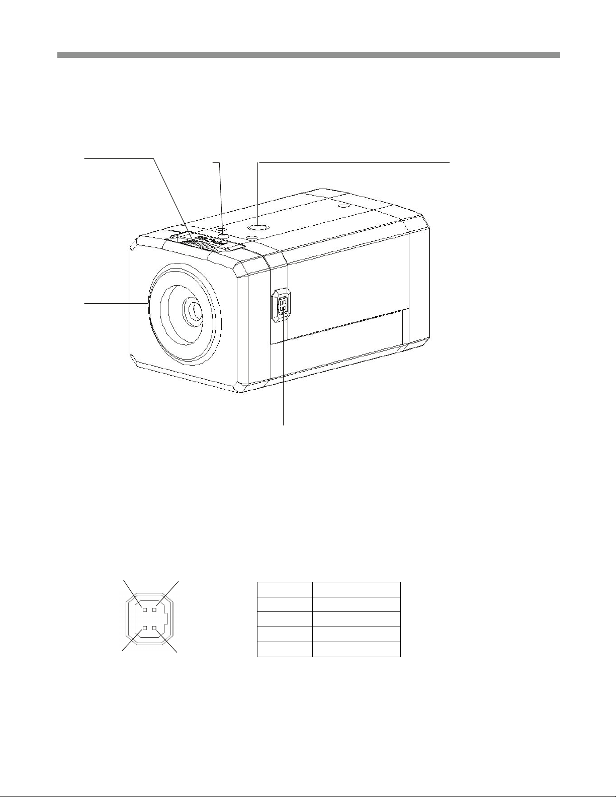
4. Part Names
4.1 Front view
①
②
- Lens Connector for Auto-iris lens (DC Drive)
① Back Focus Adjustment ② Dust Protection Cap
③ Lens connector for auto iris lenses ④ Back focus Adjustment Lock Screw
⑤ Camera Mount Hole (Top and Bottom)
PIN 4 PIN 2
PIN 3 PIN 1
④
③
PIN No DC Iris
1 Damp(-)
2 Damp(+)
3 Drive(+)
4 GND
⑤
6
Page 7

VTC-C750WDR
4.2 Rear side view
ⓐ
ⓐ OSD menu switches (Up/ Down/ Left/ Right / Enter)
ⓑ Video Output Connector (BNC)
ⓒ Power indicator LED
ⓓ Power Input Terminal
ⓑ
ⓒ
ⓓ
5. Installation and commissioning Instructions
• Make sure the power is removed before the installation.
• Follow the order for applying power.
First connect the low voltage (DC12V or AC24V), then plug the AC adapter to AC outlets to avoid an
improper reset from power jitter and a damage from the surge voltage when no load.
5.1. Attaching the lens
• Remove the Dust Protection cap from the lens mount
• Screw the lens onto the camera without using force
5.2. Setting the back focus lock
The back focus is the distance between the lens support on the camera and the image sensor. Optimum focus
is only possible when the correct distance is set. It may be necessary to set the back focus in individual cases
due to production tolerances of the lens. The iris of the lens must be open as wide as possible. (smallest F
value) to set the back focus. For lenses with automatic iris control, you will require a ND filter (gray filter) to
prevent the iris from closing in bright light.
Setting for lenses with a fixed focal distance
If the focus cannot be set exactly by turning the focus ring (lens), please proceed as follows;
1. Point the camera at an object with sufficient contrast. The distance to the object should be longer than
1,000 x the focal distance.
2. Open the iris on the lens
3. Set the focus of lens so that the distance at the lens is close to infinity but not to exact infinity position.
7
Page 8

VTC-C750WDR
4. Loosen ④ Back focus Adjustment Lock Screw one~two turns on the camera with industrial “+” driver
5. Rotate ① Back Focus Adjustment until the optimum focus is achieved.
6. Tighten ④ Back focus Adjustment Lock Screw
7. Trim the focus precisely at lens if necessary.
Setting for lenses with a variable focal distance (zoom)
If the focus changes as the focal distance changes, please proceed as follows.
1. Point the camera at an object with sufficient contrast at a distance of approximately 2 meters.
2. Open the iris on the lens
3. Set the maximum focal distance (Tele) at the lens
4. Set the optimum focus with the focus ring
5. Set the smallest focal distance (wide angle)
6. Loosen ④ Back focus Adjustment Lock Screw one~two turns on the camera with the industrial “+” driver
7. Adjust ① Back Focus Adjustment until the optimum focus is achieved. Steps 3,4,5 and 7 may be needed
to repeat several times to obtain the best results
8. Tighten ④ Back focus Adjustment Lock Screw again
5.3. Installation
The camera has a 1/4” thread insert on its top and bottom side for mounting the camera to a tripod or the wall
or ceiling with a corresponding mount.
5.4 Commissioning
• Connect the power to the camera firstly
• Plug the power adaptor to the mains supply secondly
•
ⓒ Power indicator LED will be lit
• The camera is ready for operation
5.5. Power Supply Connections
Camera can work with either 12VDC or 24VAC, dual voltage power. It does NOT require the polarity-matched
connection for 12VDC supply. Primary and secondary grounds are completely isolated to avoid the possible
ground-loop problems. Its excellently wide operating voltage range of 10.5V-30V for DC and 12-28.8V for AC
gives an extra flexibility at the installation.
again.
6. Start up
When the camera is powered properly, it starts up with initializing the internal parameters and the filter switch
mechanism. The filter switch unit repeats IN and OUT two times at each power up and just after RESTORE
FACTORY SETTINGS.
8
Page 9

7. SETUP Menu
7.1 In the menu
Use
to select or enter.
7.2 Entering menu
Press
7.3 PRESET menu
PRESET menu is provided to help the settings with the possible parameters obtained and
assumed by the factory tests for the most common environments.
PRESETs may not be the best optimized settings for the actual installations.
In such cases, find the optimal settings in CUSTOM setting of EXPOSURE menu
<NORMAL>
INDOOR
OUTDOOR
FL-LIGHT
LOBBY Optimized for the common installation at lobby.
WAREHOUSE Optimized for the common installation at warehouse
, buttons to move menu, , buttons to change the settings and press button short
button stands for MENU or ENTER button.
button longer than 2 sec on the back of camera.
PRESET Descriptions
Produces an image that has average contrast and suitable for normal indoor or lowcontrast outdoor scenes.
Provides better leveling of image for in the darker areas of the scene. Suitable for
indoor scenes that have higher contrast lighting.
Optimized for outdoor sunlit applications and provides better leveling for the brighter
areas. Suitable for outdoor scenes having high contrast between sunlit and
shadows.
Reduces the color rolling by fluorescent lights when line-lock is not
available(NTSC). DC auto iris lens is required.
Use Line-lock sync. with AC24V supply for the best result against the color rolling if
possible.
VTC-C750WDR
9
Page 10

VTC-C750WDR
7.4 EXPOSURE menu
EXPOSURE menu is provided to help the settings with the possible parameters obtained and
assumed by the factory tests for the most common environments.
EXPOSURE presets may not be the best optimized settings for the actual installations.
In such cases, find the optimal settings in CUSTOM setting of EXPOSURE menu
EXPOSURE Descriptions
<WDR MID> Medium level of the dynamic range control for each PRESETs.
WDR HIGH Increases the dynamic range control. Some highlight area may washed out.
CUSTOM... Provides more flexible compensation other than WDR MID, WDR LOW, WDR HIGH
BLC...
WDR LOW Decreases the dynamic range control.
Compensates the brightness of main object against the bright back light.
A zone out of CTR SPOT, UPPER1/3, MIDDLE1/3, LOWER1/3 can be set.
Dynamic range control is inoperative if EXPOSURE is set to BLC.
7.5 CUSTOM menu
To enter CUSTOM menu, press
button at <CUSTOM . . . > of EXPOSURE menu.
10
Page 11

VTC-C750WDR
WDR
CUSTOM
WINDOW
Metering of the dynamic control is weighted to the selected window from SAFE AREA,
ZONE ADJUST, CENTER 1/3 AND LOWER 2/3.
Descriptions
RANGE Adjusts the strength of the dynamic range control.
BIAS Adjusts the base level of the dynamic range control.
7.6 ZONE ADJ menu
Adjusts the size and the location of the metering zone for the dynamic range control.
Dynamic range control is very sensitive to the size and the location of the zone.
The default window size is SAFE AREA.
To enter ZONE ADJ menu, press
button at <ZONE ADJ . . .> of WDR CUSTOM menu.
In ZONE ADJ menu, 'NEXT:MENU-' stands for 'press
and 'RETURN:MENU---' means 'press
button longer than 2 sec for return or exit'.
button short for next menu'
, , , buttons are used for move, enlarge or reduce the zone.
White zone boundary moves the zone to locate it at the optimal position.
Green zone boundary enlarges the zone.
Red zone boundary reduces the zone.
7.7 BLC ZONE SELECT menu
To enter BLC ZONE SELECT menu, press
button at <BLC . . . > of EXPOSURE menu.
Metering of the backlit compensation control is weighted to the selected window from CTR SPOT(1/9 of
entire screen), UPPER 1/3, MIDDLE 1/3 and LOWER 1/3.
11
Page 12

VTC-C750WDR
7.8 DAY / NIGHT menu
DAY/NIGHT Descriptions
<AUTO BW>
OFF IR Cut filter is stuck and is NOT switch OUT.
7.9 DAY/NIGHT SETUP menu
DAY/NIGHT
SETUP
EXIT
THRES
EXIT
DELAY
IR Cut filter is switched OUT/IN at night/day time automatically.
At night mode, camera outputs the B/W video without the color burst signal.
IMPORTANT!!!
Descriptions
IMPORTANT!!!
DAY->NIGHT and NIGHT->DAY operations must be examined and verified at the final
step of the installation because they may be affected by the settings such as the size or
location of the metering window.
Block the lens for a few seconds for NIGHT mode and release it to be returned to DAY
mode. If camera stay at NIGHT mode more than 10sec, increase EXIT THRES and
repeat the fore mentioned steps. If the scene is too dim, it may not be returned to DAY.
If set to ON, camera insert 8~10sec delay for NIGHT to DAY transition.
This is to avoid the unnecessary transitions between NIGHT and DAY by the short
duration of light such as car lights.
12
Page 13

7.10 SHUTTER LIMIT menu
SHUTTER
<2X ESS >
4X ESS ~
32X ESS
LIMIT
The longest shutter is limited to 2X of 1/60(NTSC)/1/50(PAL) sec when the scene
illumination becomes dim.
Video refresh rate at 2X ESS is 15(NTSC)/12.5(PAL)frames/sec.
The longest shutter is limited to 4X~32X of 1/60(NTSC)/1/50(PAL) sec when the scene
illumination becomes dim.
The higher integration increases the sensitivity but decreases the video refresh rate.
Descriptions
7.11 WHITE BALANCE menu (in PITURE CONTROL menu)
To enter PICTURE CONTROL sub-menu, press
button at PICTURE CONTROL of MENU-1.
WHITE
BALANCE
<ATW
NORMAL>
ATW Desat
White balance is compensated automatically in range of 2800K-7500K
White balance is compensated automatically in range of 2000K-11000K. In the range of
2000-2800K and 7500-11000K, white balance is gradient-compensated.
Descriptions
ATW Xtnd White balance is compensated automatically in range of 2000K-11000K
MANUAL White balance can be adjusted by either KELVIN or R/B.
VTC-C750WDR
13
Page 14

VTC-C750WDR
7.12 MANUAL WHITE BALANCE menu (in PITURE CONTROL menu)
To enter MANUAL WHITE BALANCE menu, press
button at <MANUAL...> of WHITE BALANCE menu.
Shoot a white paper or a gray card and adjust either KELVIN or R/B so that the color on the monitor
becomes most white.
7.13 BRIGHTNESS, DNR, SHARPNESS, FLIP, COLOR SELECT and SATURATION menus
(in PITURE CONTROL menu)
PICTURE
CONTROL
BRIGHTNESS
BRIGHTNESS level is a kind of video output gain and is different from the iris level
control. It can be set to MID-LOW, MIDDLE, MID-HIGH, HIGH and LOW.
If it is set too high, the dynamic range is decreased.
Descriptions
DNR ON reduces the dynamic noise but effects SHARPNESS a little soft.
SHARPNESS MIDDLE, HIGH, MAX, LOW
FLIP
COLOR
SELECT
SATURATION Color saturation can be adjusted between -2 and +2.
OFF provides the normal video.
H-FLIP(V-FLIP) provides the horizontally(vertically) flipped video.
H/V-FLIP provides the horizontally and vertically flipped video.
Four sets of COLOR variance are provided.
14
Page 15

VTC-C750WDR
7.14 LENS SELECT menu
DC auto iris lens or MAUAL lens can be used for this camera but DC auto iris lens must be used in
FL-LIGHT and EFR presets and strongly recommended in other presets when the scene is very bright.
7.15 VIDEO SYNC menu
VIDEO SYNC Descriptions
<INT > Synchronization is INTERNAL regardless of the power source.
INT2
AUTO…
Synchronization is INTERNAL but sync frequency is modified to simulate line-lock.
It is not actually synchronized to the line frequency.
Synchronization mode is decided automatically by the power source.
Line-lock for AC24V and Internal for DC12V
15
Page 16

VTC-C750WDR
7.16 SAVE / RESTORE / EXIT menu
SAVE AND EXIT Exits menu after saving the parameters.
MENU-2 Descriptions
EXIT NO CHANGES Exits menu with discarding any changes.
RESTORE
FACTORY SETTINGS
LANGUAGE
VIDEO STANDARD
Restores and saves all parameters of factory settings.
Camera resets and restarts automatically.
English is available only.
Language does NOT change by RESTORE FACTORY SETTINGS.
NTSC and PAL can be switched. VIDEO STANDARD does NOT change by
RESTORE FACTORY SETTINGS
16
Page 17

8. Specifications
Model name VTC-C750WDR VTC-C750WDR/PAL
Image Device 1/3" RGB Color DPS SENSOR (Pixim Orca D1500series)
Effective Pixels 720(H) x 540(V)
TV system NTDC, 525lines / 2:1interlace PAL, 625lines / 2:1interlace
Scan frequency. 59.94Hz(V), 15.734Khz(H) 50Hz(V), 15.625Khz(H)
Synchronization Internal/Line lock (Default: Internal)
H. Resolution 550 TV Lines
Sensitivity 0.0002Lux(F1.2,@40IRE, DN(DSS mode + ICR mode))
S/N Ratio 50dB with AGC OFF at 50IRE
White Balance 2000~11000ºK Automatic tracking
WDR mode 4 presets (Low / Middle / High / Custom )
Auto Iris Control DC drive iris control. Level control is fixed internally.
VTC-C750WDR
Slow shutter 2X, 4X, 8X, 16X, 32X ESS
BLC Zone 4 areas (CTR SPOT, UPPER 1/3, MIDDLE 1/3, LOWER 1/3)
Presets NORMAL, INDOOR, OUTDOOR, FL-LIGHT, LOBBY, WAREHOUSE
Flicker reduction Yes (NTSC Version only)
OSD Yes (Setup menu only)
Video Output VBS 1Vpp +/-10%, 75ohm
Lens mount CS mount
Power 24VAC(12V-28.8Vac) or 12VDC(10.5-30Vdc), 5Watts max
Operation Temperature -10ºC~+50ºC, 85% RH. Max. non-condensing
Dimensions (W x H x L) 2.56" x 2.17" x 4.17" (65mm x 55mm x 106mm)
Weight 9.52 Oz. (270g)
● Design and specifications are subject to change for product improvements without prior notice.
17
Page 18

VTC-C750WDR
9. Dimensional Drawings
(Unit: mm)
18
Page 19

10. Setup Menu Tree
VTC-C750WDR
19
Page 20

28492 CONSTELLATION ROAD VALENCIA, CA 91355
WWW.VITEKCCTV.COM | 888-VITEK-70
 Loading...