

Page 1
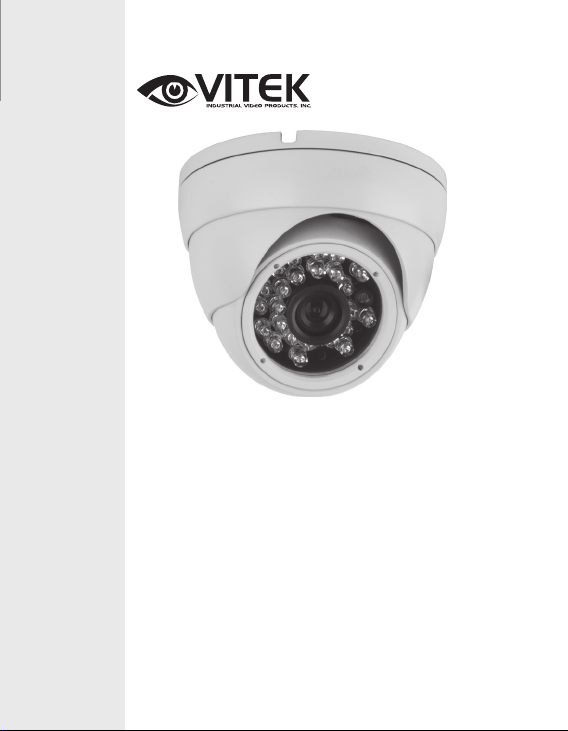
VTC-BRE24F
Day/Night 960H Infrared
VITEK
• 1/3” High Resolution CCD
• 700 TV Lines of Resolution (960H)
• E-WDR by Adaptive Tone Reproduction
• 24 Dynamic Infrared LEDs with up to 65’ Range
• 0.003 Lux / 0 Lux with IR LEDs On
• IR Corrected 3.6mm Fixed Iris Lens
• 2DNR Noise Reduction
• Motion Detection, Privacy Masking & Highlight Masking
• OSD (On Screen Display) menu
• 12 VDC Operation
Ball Camera
Page 2
CAUTION
RISK OF ELECTRICAL SHOCK
DO NOT OPEN
CAUTION:
To reduce the risk of electric shock, do not expose this apparatus to rain or moisture.
Only operate this apparatus from the type of power source indicated on the label.
The company shall not be liable for any damages arising out of any improper use, even if we
have been advised of the possibility of such damages.
PACKAGE CONTENTS
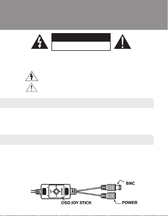
CONNECTION
1. Connect the camera video output to the monitor video input with a 75Ω coaxial
cable.
2. DC12V Input Terminal
Connect the power connector of the camera to a 12V DC regulated power supply.
NOTE: Please use the correct power adaptor, DC12V (regulated), to operate this
unit. The tolerance of this unit is DC12V ± 10%. Over the maximum DC12V power
input will damage the video output connector (VIDEO OUT).
The lightning fl ash with arrowhead symbol, within an equilateral triangle, is
intended to alert the user to the presence of uninsulated “dangerous voltage”
within the product’s enclosure that may be of suffi cient magnitude to constitute
a risk of electric shock to persons.
This exclamation point within an equilateral triangle is intended to alert the
user to the presence of important operating and maintenance (servicing)
instructions in the literature accompanying the appliance.
1 x VTC-BRE24F Camera
1 x Mounting Bracket
1 x User Manual
1 x Hex Wrench
1 x Mounting Screws/Anchors Pack
1 x Mounting Template
Page 3
VTC-BRE24F / VTC-IRE24F
The lightning flash with an arrowhead symbol, within an equilateral
triangle is intended to a lert the user to the pres ence of non-insulated
dangerous voltage within the product’s enclosure that may be of sufficient
magnitude to constitute a risk of electric shock to persons.
The exclamation point within an equilateral triangle is intended to alert the user
to the presence of im portant operating and maintenance (servicing) instructions
in the literature ac companying th e appliance.
This installation should be made by a qualified service person and should conform to all local codes.
Page 4

VTC-BRE24F / VTC-IRE24F
Contents
1. EXPOSURE
2. DAY & NIGHT
3. WHITE BAL
4. MONITOR
5. IMAGE
6. DNR
7. MOTION
8. SYSTEM
9. EXIT
Page 5
VTC-BRE24F / VTC-IRE24F
Warning
Contact an authorized technician for inspection.
If you use your camera around smoke or unusual heat for a long time, fire may
be caused.
Unless the surface is suitable, it could cause falling or other hazards.
It may result in fire, electric shock or other hazards.
It could cause an electric shock.
It
may result in fire or other hazards.
Page 6
VTC-BRE24F / VTC-IRE24F
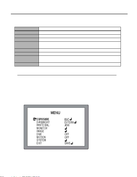
[OSD Menu]
EXPOSURE
ALC / ELC
DAY / NIGHT
DAY / NIGHT / AUTO / EXTERNAL / CDS
WHITE BAL
MANUAL / PUSH / ATW
MONITOR
GAMMA / CHROMA / SHARPNESS / SHADING / PED.LV
IMAGE
BACK LIGHT / CONTRAST / POSI/NEGA / H-MIRROR /
PRIVACY
DNR
LOW / MIDDLE / HIGH / OFF
MOTION
ON / OFF
SYSTEM
CAM TITLE / CAM ID / ID DISP / SYNC / BAUDRATE /
LANGUAGE / SPECIAL
EXIT
SAVE / MANUAL / INITIAL / RESTORE
How to use OSD button(Tact Switch) in OSD control board or OSD cable
Press : enter into OSD menu and save settings at EXIT.
Push UP / DOWN : select function wish to activate.
Push LEFT / RIGHT : adjust level / value and mode of sub-menu
OSD Main Menu
Page 7

VTC-BRE24F / VTC-IRE24F
MAIN MENU
DEFAULT
DESCRIPTION
EXPOSURE
Select Lens type according to mounted
/ built-in lens.
* ELC : Electronical Iris Lens
(Manual Iris Lens / Fixed Foca l Lens).
* ALC: Auto Iris Lens(DC)
DAY&NIGHT
* AUTO: DAY or NIGHT is decided
automatically by light level coming through
lens.
* DAY: Color video output
* NIGHT: B/W video output regardless of
light level
* EXT: Day(Color) or Night(B/W) is decided by
external light sensor or LED control board
All IR LED cameras should set EXT.
* CDS: Not used
WHITE BAL
ATW
* ATW (Auto Tracking White Balance)
* MANUAL: Adjust White Balance with
fixed values of BL UE and RED
* PUSH: White Balance is performed w hen
enter button of OSD is pressed
MONITOR
* Set GAMMA, CHRO MA, SHARPNESS,
SHADING & PED. LEVEL of Monitor
IMAGE
* BACK LIGH: Select HLC or BLC and adjust it.
* Select CONTRAST ON or OFF
* POSI / NEGA: Select Posi or Nega imag e.
* H-MIRROR: Select MIRROR ON or OFF
* PRIVACY: Set PRIVACY ON or OFF
DNR
OFF
Set DNR level, LOW or MIDDLE or HIGH
MOTION
OFF
Select MOTION ON or OFF
SYSTEM
Set CAM TITLE, CAM ID, ID DISP, SYNC,
BAUDRATE, LANGUAGE and SPECIAL
EXIT
SAVE, MANUAL, INITIAL, RESTORE
Page 8

VTC-BRE24F / VTC-IRE24F
1. EXPOSURE
Select lens type in accordance with mounted/built-in lens.
* ALC : Auto Iris Lens
* ELC : Electronic Iris Lens
(Fixed Focal Lens / Manu al Iris Vari-focal Lens)
EXPOSURE
(ALC / ELC)
DEFAULT
DESCRIPTION
BRIGHTNESS
Adjust the brightness level of screen when the
environment is extremely bright or dark.
SHUTTER
AUTO
Adjustable shutter speed. This is useful when
the light condition is ch anging quickly
* Set AUTO, 1/50 ~ 1/120K
FLK
OFF
Select FLICKERLESS ON or OFF. In the FLK
ON, sensitivity will be reduced under low light
AGC
20
Setting AGC level, 0 ~ 20. The higher gain
level, brighter picture with more noise.
2. DAY & NIGHT
DAY &
NIGHT
DEFAULT
DESCRIPTION
DAY &
NIGHT
IR LED
CAMERA : EXT
NONE IR
CAMERA :
AUTO
* AUTO: Camera decide DAY or NIGHT by
himself through incoming light level.
ICR is also movin g DAY or NIGH T (ICR
Version).
* DAY: Camera works as a regular color
camera.
ICR is inserted to cu t IR spectrum from light
(ICR built-in Came ra)
Page 9

VTC-BRE24F / VTC-IRE24F
DAY &
NIGHT
DEFAULT
DESCRIPTION
DAY &
NIGHT
* NIGHT: Camera works as a regular B /W camera.
ICR move to pa ss IR spectrum.
* CDS : Not used
* EXT : DAY or NIGHT is decided by extern al
signal(included CDS sensor) built in camera.
All of IR LED Cameras must be set to EXT.
2-1. AUTO
Usually cameras with no IR LED is set AUTO. But IR LED cameras should set
EXT.
AUTO
DEFAULT
DESCRIPTION
AGC THRS
11
* Setting threshold level to switch from to DAY <-->
NIGHT.
AGC
MARGIN
* Setting threshold margin to switch from to DAY
<--> NIGHT.
* If AGC margin is too small, may occur switching
D <--> N repeatly. Recommend more than 10
D/N DELAY
3SEC
* Dwell time before switch D <--> N after check
light level. * DEL AY can avoid unnecessary
switching by short term light.
* To make right switch D <--> N, camera should
retain the present environme nt for longer than
DELAY(DWELL TIME).
B/W BURST
OFF
* Select BURST ON or OFF
SMART IR
* Not used (Camera with no IR LED set Au to and
no need SMART IR)
Page 10

VTC-BRE24F / VTC-IRE24F
Page 11

VTC-BRE24F / VTC-IRE24F
2-2. NIGHT
NIGHT
DEFAULT
DESCRIPTION
BURST
OFF
* Select BURST ON or OFF
SMART IR
OFF
* Set LED POWER, ANT I-SAT & SAT AREA.
Can set SAT AREA when use ANTI-SAT.
Note: If set D&N at Night, White Balance is not activated.
2-3. EXT
EXT
DEFAULT
DESCRIPTION
EXTERN
S/W
* Must keep HIGH (IR LED Cam eras only).
If use LOW, pictur e changes to B/W .
D / N
DELAY
3SEC
* Dwell time before switc h D <--> N after check
light level.
* DELAY can avoid unnecessary switching by
short term light.
* To make right switch D <--> N, camera should
retain the present environme nt for longer than
DELAY(DWELL TIME).
B / W
BURST
OFF
* Select BURST ON or OFF
SMART IR
* Set LED POWER, ANT I-SAT & SAT AREA.
Can set SAT AREA when use ANTI-SAT.
3. WHITE BAL
WHITE BAL
DEFAULT
DESCRIPTION
WHITE BAL
ATW
* ATW(Auto Tracking White Balance )
* MANUAL: Adjust White Balance with fixed values
of BLUE and RED. User can adjust the color and
temperature by c ontrolling RED an d BLUE gain
Recommend to use when the light temperature is
fixed all the time.
* PUSH: Use when White Balan ce is deviated.
Press Enter(Set) button. White Balance is
performed whenever the enter(set) button is
pressed
Page 12

VTC-BRE24F / VTC-IRE24F
4. MONITOR
* Set GAMMA, CHROMA, SHARPNESS, SHADING & PED. LEVEL of Monitor
5. IMAGE
5-1. BACK LIGHT
5-1-1 BLC
Page 13

VTC-BRE24F / VTC-IRE24F
BLC
DEFAULT
DESCRIPTION
LEVEL
MIDDLE
* Set up BLC LEVEL, MIDDLE , HIGH or OFF
DISPLAY
* Select ON or OFF of BLC area.
BLC area appear in blue square frame.
TOP/BOT
TOM
* Adjust size of BLC area by moving
TOP / BOTTOM / LEFT / RIGHT menu.
BLC is useful function to see outside from inside under the environment bright
background of the object
BLC ON BLC OFF
5-1-2 HLC : HLC cut out highlighted area then mask it with black color. Can
set HLC level
HSBLC ON
HSBLC OFF
5-2. CONTRAST
Set D-WDR & DEFOG or OFF
5-2-1 D-WDR
D-WDR
DEFAULT
DESCRIPTION
D-WDR
* Selectable AUTO or MANUA L
LEVEL
* Set D-WDR level, LOW / MIDDLE / HIG H
Page 14

VTC-BRE24F / VTC-IRE24F
5-2-2 DEFOG
5-2-3 POSI / NEGA
Selectable POSI or NEGA image.
5-2-4 H-MIRROR Selectable MIRROR ON or OFF
5-2-5 PRIVACY
This helps you can mask areas you not want to see but want to hide on
the screen, offering to tal 8 masking zones.
PRIVACY
DEFAULT
DESCRIPTION
MASK LV
* Can select a masking color for each masking
area out of the 12 colors
AREA NO
* Selectable up to 8 area
DISPLAY
* Select ON or Off. ON --> Display the selected
masking area
TOP/
BOTTOM
* Adjust size of selected masking area
Page 15

VTC-BRE24F / VTC-IRE24F
6. DNR
DNR(Digital Noise Reduction) is technology useful at low light.
But too strong reduction may occur tail effect and loss sharpness.
* Can choose DNR level, LOW / MIDDLE / HIGH
7. MOTION
Motion Detection allows to observe moving object in 4 different areas on the
screen. Programmable Area No, Size, position, sensitivity and display ON or
OFF
Note : When detect something, display “MOTION ! ! !” on the monitor.
MOTION
DEFAULT
DESCRIPTION
SENSITIVITY
* Set sensitivity of detection
AREA NO
* Selectable detection area up to 4 ares.
AREA USE
* Determines whether use the selected area or no t
TOP /
BOTTOM..
* Adjust size of selected area.
Page 16

VTC-BRE24F / VTC-IRE24F
8. SYSTEM
SPECIAL
DEFAULT
DESCRIPTION
CAM TITLE
OFF
* Can make camera name u p to 8 letters by
using UP / DOWN button
Can use 0~9 & A~Z
* LEFT / RIGHT button : choose lettering posion
* ON: Camera name(cam era title) is displayed
on left top of the screen
CAM ID
* Set camera ID No. up to 256 fro m 0 to 255
ID DISP.
* On : Camera ID No. is displayed on right top
of the screen
SYNC
* Fixed INT(Internal Sync)
BAUDRATE
* Set Baud Rate, 2400 / 4800 / 9600 / 57600
/ 115200
LANGUAGE
* Available ENGLISH / CHINESE
SPECIAL
* Detect and compansate defective pixel.
* Selectable Font color of OSD Menu
(support total 8 colors)
Page 17

VTC-BRE24F / VTC-IRE24F
8-1. CAM TITLE
*Can input max. 8 letters with A~Z & 0~9 by using UP / DOWN button.
*LEFT / RIGHT: move CAM TITLE input position
Note) If ‘OFF’ is selected, the CAM TITLE does not appear on the
monitor even if it has been inputted.
9. EXIT
SAVE: Save all of adjusted(changed) value
RESTORE: Return to before setting
INITIAL: Return to factory default
MANUAL: Keep changed data & value but not saved. After turn off then turn
on, return to before setting value.
Page 18

Detailed Specifications VTC-BRE24F
Image Device
Resolution
Effective Pixels
Minimum illumination
Infrared LEDs
IR Distance
Day/Night
Built-In Lens
Light Compensation
Noise Reduction
White Balance
E-WDR
Motion Detection
Privacy Mask
Water Resistance
Power Source
Operating Conditions
Dimensions
1/3” High-Resolution Inter-Line CCD (960H)
700 TVL (960H)
976(H) x 494(V)
0.003 Lux (0 Lux with LED ON)
24 Dynamic IR LEDs
65’ (20m)
Auto
3.6mm IR Corrected Lens
HLC (Highlight Compensation) / BLC (Backlight Compensation)
2DNR
ATW / AWB / Push
YES by ATR (Adaptive Tone Reproduction)
YES
Up to 8 Programmable Mask Areas
N/A
DC12V (±10%)
14°F to +140°F (-10°C to +60°C) @ 85% RH
2.68” x 3.15” (68mm x 80mm)
Page 19

VITEK LIMITED PRODUCT WARRANTY
VITEK products carry a three (3) year limited warranty. VITEK warrants
to the purchaser that products manufactured by VITEK are free of
any rightful claim of infringement or the like, and when used in the
manner intended, will be free of defects in materials and workmanship
for a period of three (3) years, or as otherwise stated above, from the
date of purchase by the end user. This warranty is non-transferable
and extends only to the original buyer or end user customer of a Vitek
Authorized Reseller.
The product must have been used only for its intended purpose, and
not been subjected to damage by misuse, willful or accidental damage,
caused by excessive voltage or lightning.
The product must not have been tampered with in any way then the
guarantee will be considered null and void.
This guarantee does not affect your statutory rights.
Contact your local VITEK Reseller should servicing become necessary.
Vitek makes no warranty or guarantee whatsoever with respect to
products sold or purchased through unauthorized sales channels. Warranty support is available only if product is purchased through a Vitek
Authorized Reseller.
28492 Constellation Road ValenCia, Ca 91355
WWW.ViteKCCtV.CoM | 888-ViteK-70
 Loading...