

Page 1
VITEK
FEATURES:
• 1/3” 2.1 MegaPixel Progressive Scan CMOS sensor w/
NVP2420 DSP
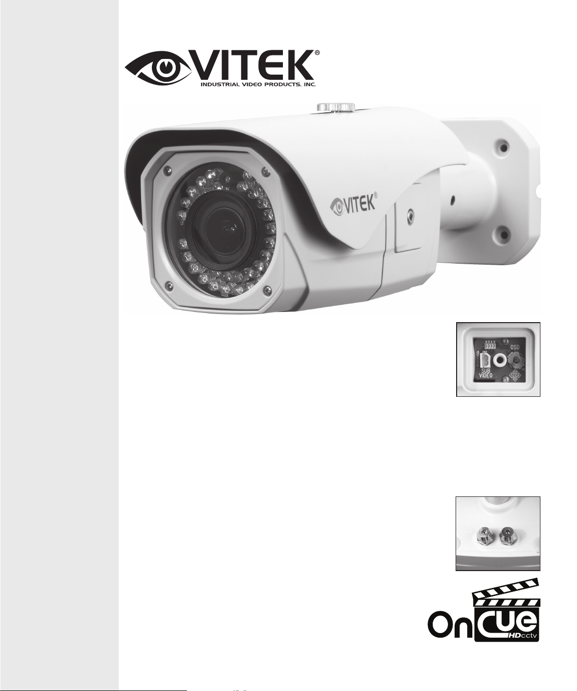
VTC-BHOC6R2812
2.1MP 3G-SDI IP68 Vandal Resistant WDR
Bullet Camera with 2.8-12mm Lens
& 42 IR LEDs
• 2.1 MegaPixel With full 1080p 3G-SDI (SMPTE 424M) @
60fps / 30fps HD-SDI (SMPTE 292M) @ 30fps Output
• 42 850nm Dynamic Intensity IR LEDs with 165’ Range
• MegaPixel IR Corrected 2.8-12mm Varifocal Lens Included
• Mechanical IR Cut Filter (True Day/Night)
• XD-DNR (2D-DNR + 3D-DNR) Noise Reduction
• 16:9 Video format
• Advanced OSD Functions: Defog, Dynamic IR, WDR,
Motion Detection, Privacy mask, Mirror, BLC/HLC, D-Zoom
• 100% Pure Digital Transmission of video data
• Up to 700’ HD Transmission Range (Depending on cable
characteristics and integrity)
• IP68 Weather Resistance
• 12VDC / 24VAC Dual Voltage Operation
External
Adjustments for
Zoom & Focus,
plus easily
accessible OSD
& secondary
video output via
side panel!
Page 2
2
Page 3

WARNINGS
The camera needs periodic inspection.
• Contact an authorized technician for inspection.
Stop using camera if there is a malfunction.
• Avoid installing camera in high heat areas, risk of fire may occur.
Do not install the camera on a surface that can not support it.
• Unless the surface is suitable, injury or other hazards may occur.
Do not disassemble the camera.
• It may result in fire, electric shock or other hazards.
Do not hold plug with wet hands.
• It could cause an electric shock.
Do not use the camera close to a gas or oil leak.
• It may result in fire or hazards.
3
Page 4

PRECAUTIONS
Ø Do not install the camera in extreme temperature conditions.
• Only use the camera under conditions where temperatures are
between -14˚F and +122˚F. Be especially careful to provide ventilation
when operating under high temperatures.
Ø Do not drop the camera or subject it to physical shocks.
• It may cause malfunctions to occur.
Ø Never point camera into a strong light source, such as the
sun or bright spotlight.
• It can damage the CMOS Sensor.
Ø Do not expose the camera to radioactivity.
• This will damage the CMOS sensor.
NOTE
• If the camera is exposed to spotlight or object reflecting strong
light, smear or blooming may occur.
• Please check power specs before connecting power.
4
Page 5

FEATURES
• 1/3” 2.0 Mega-Pixel Panasonic Progressive Scan Sensor
• Resolution: 1920 x 1080 (30P/25P, 60P/50P, 60i/50i)
• HD-SDI / SMPTE 292M (30P/25P HD-SDI), SMPTE 424M
(60P/50P 3G SDI) Video Output
• HD over Coaxial Cable
• Uncompressed HD Digital Video
• WDR
• True Day/Night by ICR
• Smart 3DNR, 2DNR / Smart IR
• RS-485 (Pelco®-D) Remote Control, Coaxial Cable Comm.
• Sens-UP: 2x ~ 30x
• Motion Detect, Mirror, Privacy Mask, De-fog, BLC/HLC, D-Zoom
5
Page 6
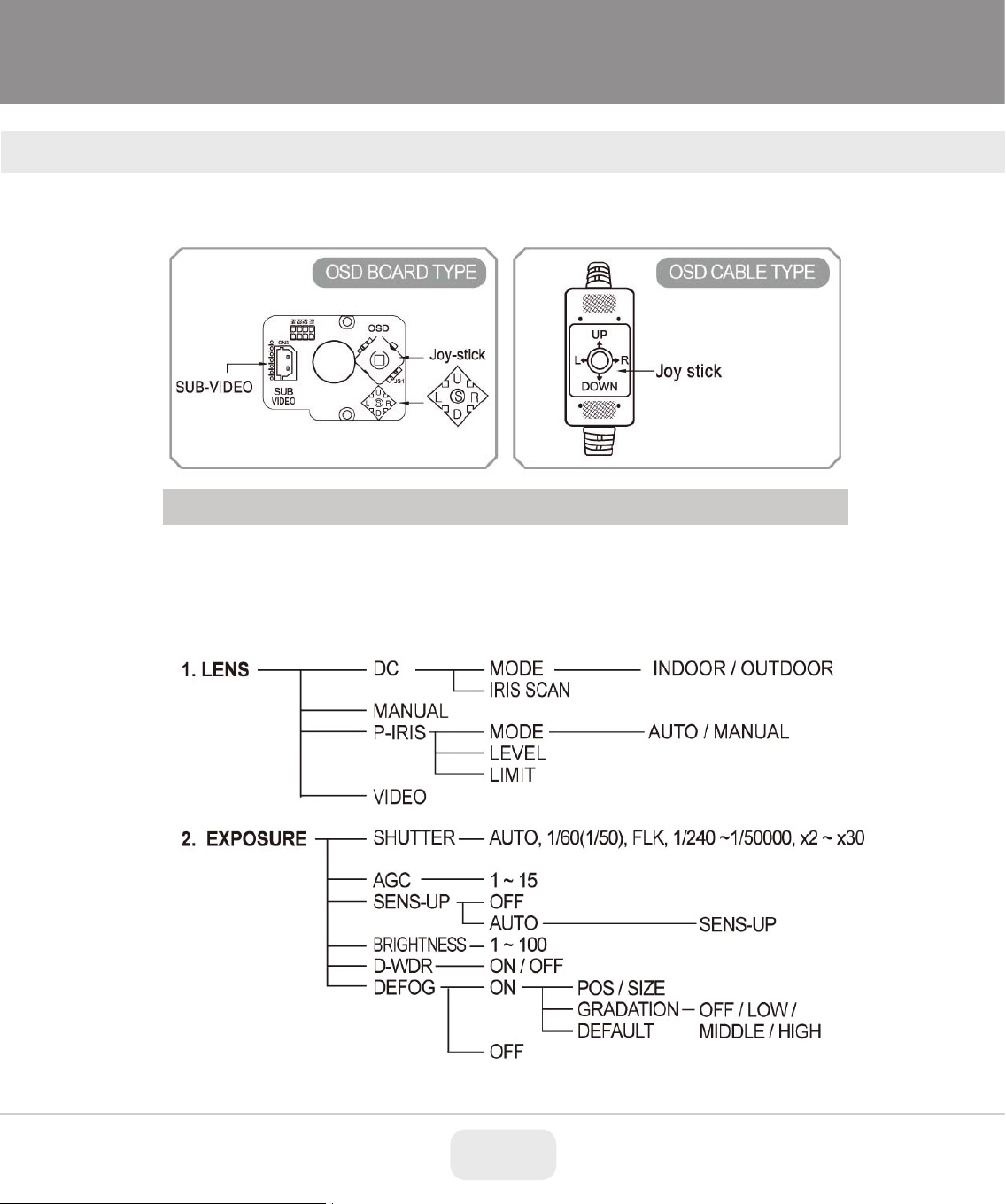
Setup Menu (OSD)
SETUP MENU (OSD)
[How to operate OSD joy stick]
OSD menu is controlled by OSD joystick in OSD Board or OSD Cable
-▲ (UP), ▼ (DOWN), ◀ (LEFT), ▶ (RIGHT), ● (SET / ENTER)
[Menu Tree]
07
6
Page 7
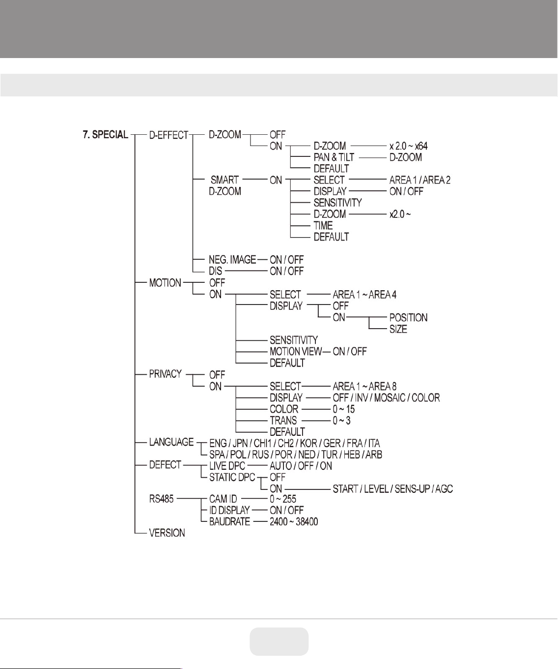
MENU TREE
[Menu Tree]
7
Page 8
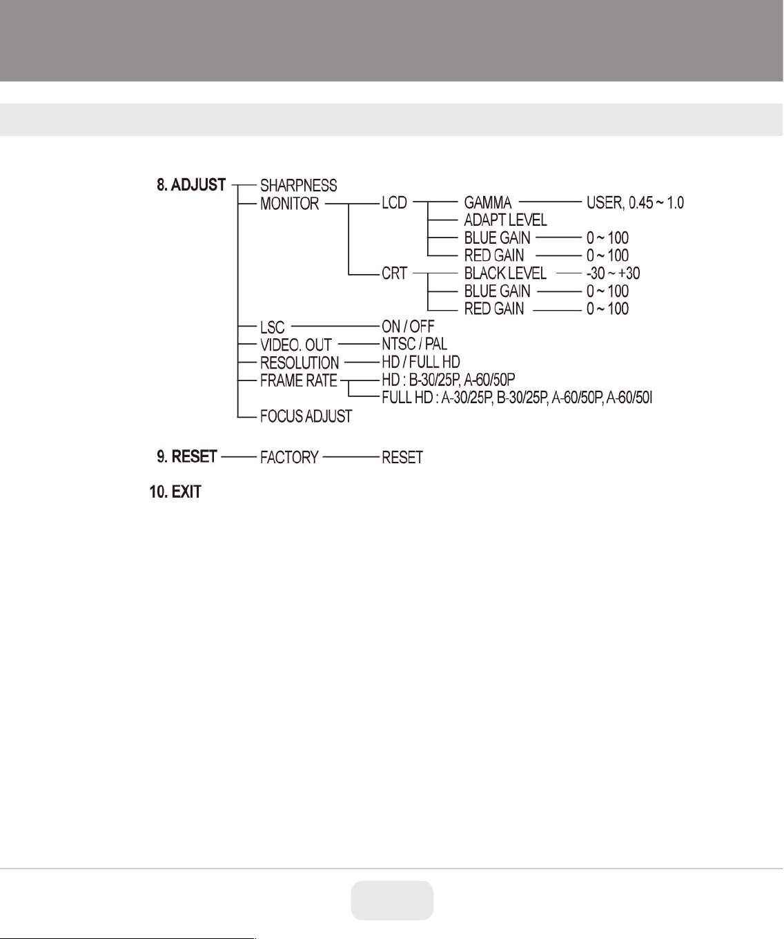
MENU TREE
[Menu Tree]
8
Page 9
MENU TREE
[Menu Tree]
9
Page 10
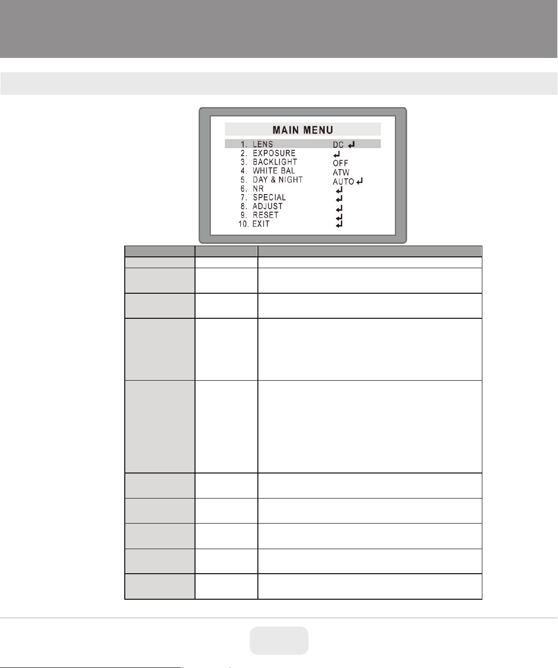
Main OSD Menu
MAIN MENU
DEFAULT
DESCRIPTION
LENS
DC
Select Lens type according to mounted or built-in lens
A
* ATW(Auto Tracking White Balance) * AWC ->
* Manual : Adjustable value of BLUE and RED
* AUTO: DAY or NIGHT is set automatically by light
All IR LED cameras should be set to EXT.
MAIN OSD MENU
EXPOSURE
BACK LIGHT
WHITE BAL ATW
DAY&NIGHT AUTO
NR
SPECIAL
ADJUST
RESET
EXIT
Set SHUTTER, AGC, SENS-UP, BRIGHTNESS,
D-WDR &, DEFOG
Select WDR, BLC, HSBLC or OFF
SET : White Balance is fixed at the value when
*(enter) is pressed and keeps the value
* INDOOR : White Balance is fixed at about 3100K
* OUTDOOR : White Balance is fixed at about 5100K
level coming in through lens. DELAY TIME, D -> N
and N -> D, can be set in the menu
* COLOR : Color video output * B/W : B/W video
output regardless of light level
(removes IR cut filter automatically)
* EXT : Day(Color) or Night(B/W) is decided by
external light sensor(CDS sensor)
* Set 2DNR, 3DNR, LEVEL, SMART NR
* Set CAM TITLE, D-EFFECT, MOTION, PRIVACY,
LANGUAGE,DEFECT & RS 485
* Set SHARPNESS, MONITOR, LSC, TV SYSTEM
(Video Out), RESOLUTION & FRAME RATE
* Push • (Enter) at FACTORY, all parameters return
to factory default.
* Save all and Exit
10
Page 11

1. LENS
Select Lens type, DC, MANUAL or P-IRIS.
EXPOSURE
DEFAULT
DESCRIPTION
Set Shutter Speed, 1/60(1/50), FLK, 1/240 ~
frame integration rate regardless of light level.
* If set to AUTO, Set limitation of maximum
set up
* D-WDR is to enhance brightness of dark areas
* If set too high, white noise will increased in the
1. LENS
DC Lens: * MODE: Set INDOOR or OUTDOOR
2. EXPOSURE
2. EXPOSURE
SHUTTER AUTO
1/50000 or x2 ~ x30
* If camera is equipped with auto iris lens,
recommended to set to AUTO.
* In the region NTSC but 50Hz power, set to FLK
(Flickerless). In the FLK mode, sensitivity will be
lowered under low light.
* X2 ~ x30, SENS-UP is working at selected
AGC
SENS-UP AUTO
BRIGHTNESS 40
D-WDR OFF
* Under lowest light level, AGC is maximized by
Automatic Gain Controller * Can set AGC level
integration frame rate 2 ~ x30
* Higher SENS-UP rate is higher sensitivity but
slower refresh rate.
* Due to long shutter time, some white dots may
appear.
* Usable at AUTO or 1/60(1/50) for A60/50P,
A60/50i & A30/25P and 1/30(1/25) for B30/25P
* Brightness level. The higher the value, the
brighter the image is.
* Brightness is controlled by the iris of auto iris
lens or shutter speed of fixed iris lens.
by partially increasing gain.
11
Page 12

dark area.
DEFOG OFF
* This is to enhance visibility in foggy
environments but the performance is limited.
BLC
DEFAULT
DESCRIPTION
* Gain will compensate the brightness of objects
dark and bright.
AREA
* This is to set the size and location of BLC area.
RIGHT button.
* Reset current settings and loads the default for
BLC setting.
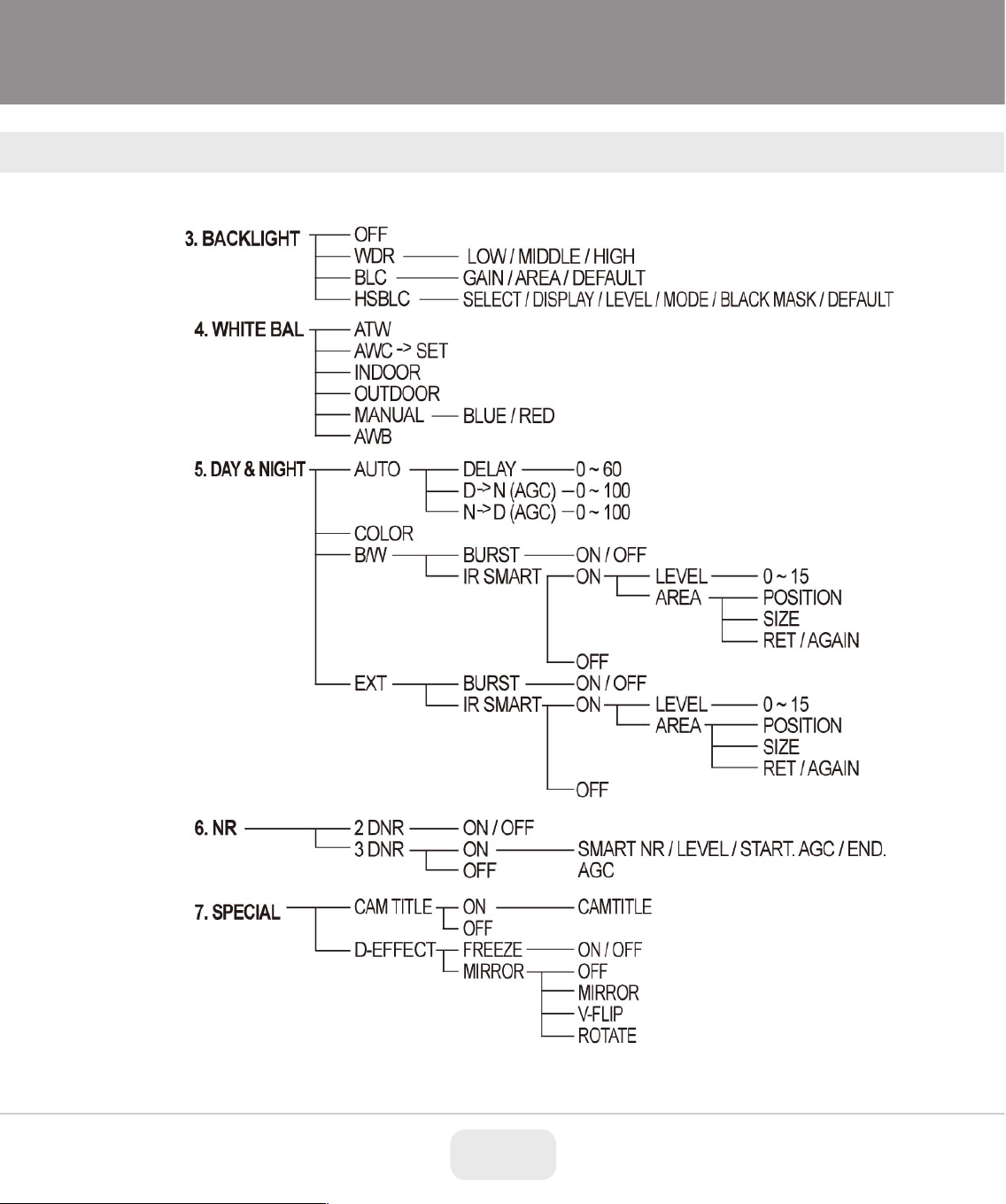
3. BACKLIGHT
3. BACKLIGHT
Select Backlight mode, WDR, BLC or HSBLC
3-1. WDR
Set WDR level, LOW, MIDDLE or HIGH
Note) WDR mode works only with HD-SDI output and not the CVBS
(composite out)
3-2. BLC
* BLC: This function is used to brighten an image in the foreground with a
highly bright area behind it such as sunlight, limiting the affect of a
silhouette
.
GAIN MIDDLE
AREA
DEFAULT AUTO
in the selected area.
* Higher GAIN can brighten the object but other
areas may saturate and noise may increase.
* BLC may not work correctly if the background is
* If the area is too small the compensation may
be unstable, and if too large it will be less
effective
* Area has 15 x 8 blocks and the SIZE and
POSITION can be set by UP/DOWN/LEFT/
12
Page 13

HSBLC
DEFAULT
DESCRIPTION
SELECT
AREA1
* Select area to adjust AREA 1~4.
* Choose ON then push ● button to enter into
Can set POSITION & SIZE of the area
* Choose ALL DAY or NIGHT
NIGHT mode only
BLACK MASK
ON
* Set ON or OFF for displaying black mask.
* Reset current settings and loads default of
HSBLC.
BLC ON
BLC OFF
3-3. HSBLC
This function is used to black out highlighted (bright) areas, in order to enable a clear
visual image of objects, such as the license plates of an oncoming vehicle or other
objects that may be obstructed by headlamps.
DISPLAY ON
LEVEL 45
MODE ALL DAY
DEFAULT
selected area.
Defines the threshold level for HLC. Lower value
is more sensitive.
* ALL DAY : HSBLC works all day regardless of
DAY or NIGHT mode
* NIGHT : HSBLC works when camera is in
13
Page 14

4. WHITE BAL
WHITE BAL
DEFAULT
DESCRIPTION
* ATW
(Auto Tracking White balance)
:
* OUTDOOR : White balance is fixed at
* AWB : Auto White Balance
4. WHITE BALANCE
HSBLC ON
WHITE BAL ATW
HSBLC OFF
White balance performs automatically
* AWC -> SET :
current scene
* INDOOR : White balance is fixed at about
* MANUAL : Adjustable fixed value of RED &
Sets the white balance to the
3100K
about 5100K
BLUE
14
Page 15

DAY & NIGHT
DEFAULT
DESCRIPTION
* AUTO : Camera switches DAY from/to NIGHT
built in IR’s
AUTO
DEFAULT
DESCRIPTION
* DELAY is dwell time before switching D->N or
for longer than DELAY (DWELL TIME).
* D->N is threshold level to switch from DAY to
mode at lower light level.
* N->D is threshold level to switch from NIGHT to
mode at brighter light level
5. DAY & NIGHT
5. DAY & NIGHT
DAY & NIGHT AUTO
5-1. AUTO
automatically according to the amount of light
through the lens.
* COLOR : Camera stays color regardless of light
level
* B/W: Camera stays black & white regardless of
light level.
* EXT : DAY or NIGHT is decided by light
sensor(CDS sensor) use this if camera has
DELAY 5
D -> N (AGC) 80
N -> D (AGC) 35
* If the gap between D -> N and N -> D value is too small, repeated
switching may occur
Recommend set the gap to more than 40
N->D after checking light level.
*DELAY can avoid unnecessary switching by
short term light.
* Camera should retain the present environment
NIGHT.
* Lower value makes the camera switch to NIGHT
DAY.
* Lower value makes the camera exit NIGHT
15
Page 16

B/W
DEFAULT
DESCRIPTION
BURST
* Set BURST ON or OFF
IR SMART
OFF
* Set IR SMART ON or OFF
EXT
DEFAULT
DESCRIPTION
BURST
* Set BURST ON or OFF
IR SMART
OFF
* Set IR SMART ON or OFF
5-2. B/W
B/W
DEFAULT
DESCRIPTION
BURST
* Set BURST ON or OFF
IR SMART
OFF
* Set IR SMART ON or OFF
5-3. EXT
EXT
DEFAULT
DESCRIPTION
BURST
* Set BURST ON or OFF
IR SMART
OFF
* Set IR SMART ON or OFF
6. NR
5-2. B/W
5-3. EXT
6. NR
2D & 3D is a powerful noise reduction technology at low light.
2DNR reduces noise with spatial frequency for each field but too strong of noise
reduction will be loss of sharpness. 3 DNR (3-dimensional noise reduction)
which reduces the noise by multi frame comparison? Noise Reduction is
effective at low light. Setting a higher level of noise reduction may result in the loss of
sharpness and the tail effect of a comet may occur.
16
Page 17

6-1. 3DNR (ON)
3DNR
DEFAULT
DESCRIPTION
* Camera is watching for any motions.
moving object.
* Set strength of 2D & 3 DNR.
and will have a tail effect in 3 DNR
* Set Start level of noise reduction
light level
* Set stop level of noise reduction
light level
SMART NR ON
* When no motion is detect: 3 DNR is working
with maximum noise reduction
automatically. This will save
HDD space on the DVR
* When motion is detected: 3 DNR deactivates
slow motion capture for
LEVEL 80
START. AGC 0
END. AGC 0
18
* Higher value, higher noise reduction.
* If set too high, sharpness will be lost in 2 DNR
* Higher level allows 3 DNR to start at brighter
* Higher level allows 3 DNR to start at brighter
17
Page 18

SPECIAL
DEFAULT
DESCRIPTION
CAM TITLE
OFF
* If set to ON, camera title is displayed.
* Can set FREEZE, MIRROR, D-ZOOM, SMART
D-ZOOM, NEG.IMAGE & DIS.
* Programmable up to 4 areas. If motion is
detected, mosaic effect appears.
PRIVACY
OFF
* Programmable up to 8 masked areas.
* Support 16 languages, ENG / JPN / CHI1 / CH2
language fonts.
* Defect pixels in the image sensor is
compensated and remapped.
* Set RS485 for remote control.
CAM ID & BAUDRATE
7. SPECIAL
D-EFFCT
MOTION OFF
LANGUAGE ENG
DEFECT
RS485
/ KOR / GER / FRA / ITA / SPA / POL / RUS /
POR / NED / TUR / HEB / ARB
* To change the language, push ● (SET/ENTER).
It will be taken about 4seconds to load new
18
Page 19

7-1. CAM TITLE
nput max.15 characters or symbols by using▲ (up)/▼ (down)/◀ (left)/▶ (right) buttons.
D-EFFECT
DEFAULT
DESCRIPTION
* freeze image and shows still image when set to
ON
* OFF : normal image display
* Cannot use if FREEZE is set to ON.
* I
* Press ● to select and the selected character/symbol will be displayed on the input line
* → ← : move CAM TITLE input position
* CLR: remove all inputted characters and symbols
* POS: move and set CAM TITLE display position
* END: finish and return to menu
7-2. D-EFFECT
FREEZE OFF
MIRROR OFF
* MIRROR / V-FLIP / ROTATE(H/V FLIP)
19
Page 20

D-ZOOM OFF
* Available max. 62x digital zoom.
usable either D-ZOOM
SMART
D-ZOOM
When motion is detected camera will digitally
zoom in
NEG.IMAGE
OFF
* If set to ON, shows negative image
* Digital Image Stabilizer. Available at A-30/25P
set up (will lose part of image)
D-ZOOM
DEFAULT
DESCRIPTION
2~64 X digital zoom, area can be scanned by
using Pan/Tilt
*Set zoom position by moving UP / DOWN / LEFT
/ RIGHT
DEFAULT
* Reset all changes in the menu
DIS
7-2.
�D-ZOOM
* PAN/TILT : set zoom position by moving
UP / DOWN / LEFT / RIGHT.
* Usable at 30/25P resolution.
Cannot synchronize with SMART D-ZOOM but
D-ZOOM X2.0
PAN/TILT
1). When entering or exiting D-Zoom video will be lost for a second so that the camera
can adjust to new setting
2). CVBS (Sub-Video) is off at D-ZOOM “ON”
20
Page 21

7-2. �SMART D-ZOOM
SMART
D-ZOOM
SELECT
* Able to set 2 areas
DISPLAY
* Set display box ON or OFF
SENSITIVITY
* Set sensitivity of D-ZOOM
TIME
* Set display time of D-ZOOM
DEFAULT
* Return to default
When motion is detected Smart D-Zoom will zoom into defined area. Smart D-zoom will
not work if D-Zoom is enabled
DEFAULT
CVBS (Sub-Video) is off when SMART D-ZOOM is “ON”
DESCRIPTION
21
Page 22

7-3. MOTION
MOTION
DEFAULT
DESCRIPTION
* Select area to be detected. Selectable up to 4
areas.
DISPLAY
ON
* Able to position area and resize motion area
* Set sensitivity value. Lower value is more
sensitive.
* ON : Enable mosaic display for the selected
area
DEFAULT
* Return to DEFAULT
SELECT AREA 1
SENSITIVITY 50
MOTION VIEW ON
7-4. PRIVACY
DEFAULT
PRIVACY
DESCRIPTIO
N
22
Page 23

Up to 8 privacy zones.
PRIVACY
DEFAULT
DESCRIPTION
SELECT
* Select the area to mask. select area 1~ 8
* Select display type, OFF, INV, COLOR or
the selected area
* Select color for masking, If color is selected in
Display each area is able to have a different color
TRANS
* Able to set the transparence of selected color
DEFAULT
* Return to DEFAULT
LIVE DPC
DEFAULT
DESCRIPTION
* Real time compensation for defective pixels
* AUTO: compensates defective pixels automatically.
LEVEL: Sets the limit for white dot noise level caused
by a defect pixel. Lower level is compensating
* OFF : Disable LIVE DPC
DISPLAY
COLOR
MOSAIC set size and position to be masked for
7-5. DEFECT
Usually image sensors have some defective pixels and they can be compensated
digitally by the image signal processor.
This menu provides compensation for the defective pixels in LIVE DPC & Static DPC
7-5. ①LIVE DPC
LIVE DPC AUTO
. Higher level of LIVE DPC can reduce Sharpness
* ON : Enable LIVE DPC able to set LEVEL
more pixels.
7-5.
②STATI
C DPC
23
Page 24

STAICE DPC
DEFAULT
DESCRIPTION
STATIC DPC ON
* Detect defective pixels while dark then saves
* OFF : Disable STATIC DPC
* Push ● button, camera will close the lens
automatically and then detect defect pixels.
* This is limit for white dots noise level caused by
a defect pixel.
* SENS-UP rate will show more defective pixels
wrong detection for regular noise.
AGC
* Set AGC level
STATIC DPC “ON”
START
LEVEL 25
the data for compensation. After starting STATIC
DPC camera will close iris automatically. It is also
recommended to cover lens during this process.
* ON : Enable STATIC DPC
SENS-UP X4
to compensate but too high of rate will cause
24
Page 25

7-6. RS485
RS485
DEFAULT
DESCRIPTION
CAM ID
1
* Set camera ID No. 0 ~ 255
* OFF: camera ID No. is not displayed.
* ON : Display the ID No on the top-right
BAUDRATE
2400
Set baud rate, 2400 / 4800 / 9600 / 19200 / 38400.
This is to set RS-485 with PELCO-D protocol for remote control.
ID DISPLAY OFF
8. ADJUST
8. ADJUST
25
Page 26

ADJUST
DEFAULT
DESCRIPTION
SHARPNESS 8
* Set sharpness level of picture.
* Select LCD or CRT monitor.
RED GAIN
* LSC (Lens shading compensation): enhance
brightness of corners (both sides).
If this is ON, more noise will be appearing.
VIDEO OUT
OFF
* Select TV system, NTSC or PAL
RESOLUTION
* Select Video Resolution, HD(720P) or FULL HD(1080P)
* Select frame rate
A-30/25P : Lowest shutter speed 1/60(50) 30fps
progressive output
A-60/50i : Lowest shutter speed 1/60(50) 60fps Interlace
output
B-30/25P : Lowest shutter speed 1/30(25) 60fps
progressive output
B-60/50P : Lowest shutter speed 1/60(50) 60fps
progressive output
FOCUS ADJUST
* Assists if focusing Camera
. See below 8.1
* Setting to high will cause more noise and a
harsh image
MONITOR
LSC OFF
FRAME RATE B-30/25P
LCD
CRT
8-1. FOCUS ADJUST
* LCD : Adjustable GAMMA, BLUE GAIN & RED
GAIN. Higher GAMMA is increasing
Contrast but looses visibility in dark
areas.
* CRT : Adjustable BLACK LEVEL, BLUE GAIN &
Focus Adjust will assist in focusing the lens. On the left side of the screen there will be a
Blue bar and a Red bar, adjust so the Red bar is on top of the Blue bar. On the right side
of the screen there will be 2 sets of numbers, adjust focus so the lower number is as
close as possible to the PEAK number
26
Page 27

9. RESET
9. RESET
9. RESET
Push enter button at FACTORY - RESET, return to factory default.
10. EXIT
Save all then exit.
Push enter button at FACTORY - RESET, return to factory default.
10. EXIT
Note
Function List of Simultaneous Operation
0= in use X = not in use
27
Page 28

DIMENSIONS
Unit of measurement: inch (mm)
3.89in (98.70mm)
12.18in (309.30mm)
7.24in (183.80mm)
3.55in (90.22mm)
3.39in (86.00mm)
28
Page 29

SPECIFICATIONS
SPECIFICATIONS
Sensor
Resolution
S/N
Video Output
IR Illuminators
IR Color Temp.
IR Range
Dynamic Intensity IR LEDs
Lens
Auto Focus Zoom
Digital Zoom
Minimum Illumination
Day/Night
Electronic shutter speed
White Balance
Brightness
DSS (Sens-Up)
DNR
WDR
Privacy
Motion Detection
ACE (Adaptive Color Enhancement)
Advanced OSD Functions
Communication
HD Transmission Range
Weather Resistance Rating
Operating Conditions
Input Voltage
Power Consumption (12VDC)
Power Consumption (24VAC)
Dimensions
1/3” 2.1 MegaPixel Progressive Scan CMOS sensor w/NVP2420 DSP
2.1 MegaPixel (1080p / 720p)
More than 50 dB (AGC Off)
3G-SDI (SMPTE 424M) / HD-SDI (SMPTE 292M)
42 IR LEDs
850nm
165’
YES
MegaPixel IR Corrected 2.8-12mm Varifocal
N/A
YES
1.0 Lux / 05 Lux (B/W) / 0 Lux with IR On
Mechanical IR Cut Filter (True Day/Night)
1/30sec ~ 1/50,000sec
ATW / AWC / Indoor / Outdoor / Manual
Adjustable (2 ~ 30 Steps)
YES
XD-DNR (2D-DNR & 3D-DNR)
YES
YES
YES
YES
Defog, Dynamic IR, WDR, Motion Detection, Privacy mask, Mirror, BLC/HLC, D-Zoom
RS-485 (Pelco® D)
Up to 700’ (Depending on cable characteristics and integrity)
IP-68
14°-122°F (-10°-50°C) < 80% RH
12VDC / 24VAC (Dual Voltage)
275mA / 750mA
125mA / 400mA
3.89” x 3.55” x 12.18” (W x H x D)
PELCO® is the registered trademarks of their independently owned and operated companies. This product has not been
licensed or endorsed by the manufacturers of PELCO® products.
29
Page 30

OTHER PRODUCTS FROM VITEK
On Cue HD-SDI Video Recorders
VT-HDOCE Series
On Cue Series 4, 8, and 16 Channel Real Time 1080p
EX-SDI Digital Video Recorders
• 4, 8 OR 16 CH EX-SDI / Analog Inputs (hybrid) with Full 1080p Camera Support
• Now Supporting Cable distance of up to 1000’ using RG59!*
• Hybrid Operation over COAX for HD-SDI, 960H, and D1 Cameras
• Simple plug and play, point-to-point connection from camera to DVR
• Real Time Recording on all channels at 1080p (VT-HDOC4E: 120fps), (VT-HDOC8E: 240fps),
(VT-HDOC16E: 480fps)
• HDMI, VGA, and Spot BNC Outputs
• Up to 5 Internal SATA2/SATA3 HDD Slots supporting up to 20TB (5 x 4TB HDD) using Advanced
HDD Format
• External SATA Port (eSATA) Supporting up to 5x External via eSATA
• Pentaplex Operation (Playback, Recording, Backup, Network)
• Alarm In/Out
• Per channel Image Adjustment
• 4 Channel Audio In
• 32 x 24 Motion Detection Grid
• Multi channel Spot output
• Panorama (Thumbnail) Search
• Remote Viewing via CMS Software, Internet Explorer, and Mobile Phones (iOS/Android), Mac OSX App
• Linear digital zoom for live and playback
• Up to 7 Simultaneous Network/Remote Connections
• 256 Camera Remote Viewing via CMS Software
• RS485 Communication port
30
Page 31

LIMITED LIABILITY WARRANTY
VITEK products carry a three (3) year limited warranty. VITEK warrants to the purchaser that
products manufactured by VITEK are free of any rightful claim of infringement or the like, and
when used in the manner intended, will be free of defects in materials and workmanship for
a period of three (3) years, or as otherwise stated above, from the date of purchase by the
end user. This warranty is nontransferable and extends only to the original buyer or end user
customer of a VITEK Authorized Reseller.
The product must have been used only for its intended purpose, and not been subjected to
damage by misuse, willful or accidental damage, caused by excessive voltage or lightning.
The product must not have been tampered with in any way or the guarantee will be
considered null and void.
This guarantee does not affect your statutory rights.
Contact your local VITEK Reseller should servicing become necessary.
VITEK makes no warranty or guarantee whatsoever with respect to products sold or
purchased through unauthorized sales channels. Warranty support is available only if product
is purchased through a VITEK Authorized Reseller.
VERSION 1.0
FEB RUARY 2015
 Loading...