

Page 1
Warranty and Service Information
LIMITED LIABILITY WARRANTY
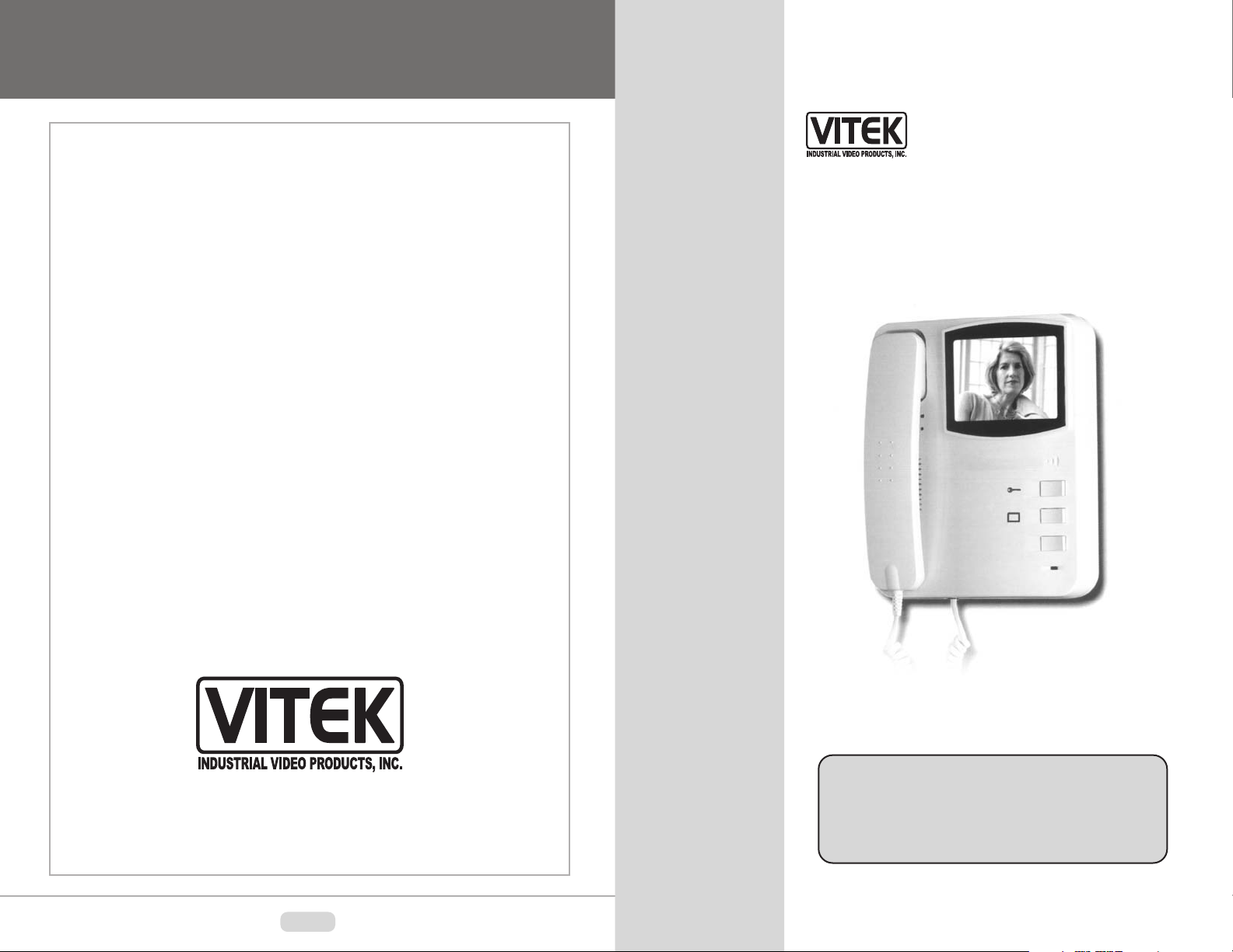
Video Door Phone
Product Manual
VITEK
Your new Video Intercom System is guaranteed free defects in
materials and workmanship for a period of one your from the
date of purchase.
The product must have been used only for its intended purpose,
and not been subjected to damage by misuse, willful or
accidental damage, caused by excessive voltage
or lightning.
The system must have been installed in accordance with the
instructions given in the instruction manual and only
compatible equipment may be connected to it.
The product must not have been tampered with in any way then
the guarantee will be considered null and void.
Should the serial numbers be tampered with in any way then
the guarantee will be considered null and void.
This guarantee does not affect your statutory rights.
Contact VITEK directly for all servicing.
VT-710S
9970 GLENOAKS BLVD. UNIT B SUN VALLEY, CA 91352
PHONE: 888-VITEK-70 / 818-771-0300 FAX: 818-771-0400
WWW.VITEKCCTV.COM | [email protected]
8
Thank you for purchasing the VT-710S Video
Door Phone from VITEK Industrial Video Products,
Inc. It’s imperative that this manual is read prior to
installation.
Page 2
IMPORTANT SAFETY PRECAUTIONS
CAUTION
RISK OF ELECTRICAL SHOCK
DO NOT OPEN
USAGE / PRECAUTIONS
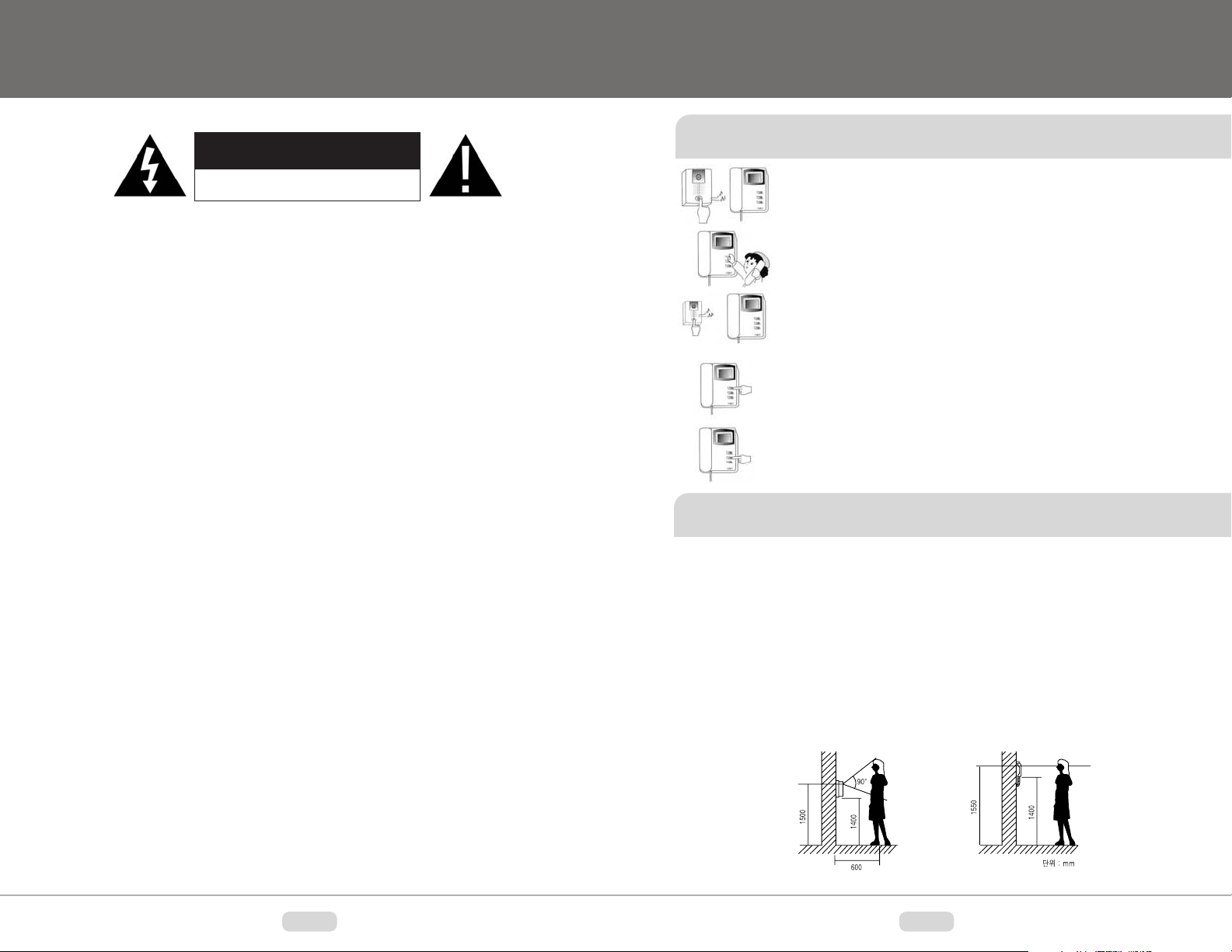
Conversing With Caller
• When a caller presses the call button on the outdoor unit, an electronic
door chime is heard over the speaker of the indoor unit and the camera
in the outdoor unit is activated. You can identify visitors with monitor.
CAUTION : TO REDUCE THE RISK OF ELECTRIC SHOCK. DO NOT
REMOVE OVER. NO USER-SERVICEABLE PARTS INSIDE. REFER
SERVICING TO QUALIFIED SERVICE PERSONNEL.
1. Unit contains uninsulated dangerous
voltage within the enclosure that may
be of sufficient magnitude to constitute
a risk of electric shock to persons
2. Only use DC Power Supply
3. Read & Keep these instructions.
4. Heed to all warnings and follow all
instructions carefully.
5. Do not use near water.
6. Clean only with dry cloth.
7. Do not block any ventilation
openings. install in accordance with the
instructions.
8. Do not install near any heat source
such as radiators, heat resisters, stoves,
or other apparatus (including amplifiers)
that produce heat.
9. Do not defeat the safety purpose
of the polarized or grounding-type plug.
A polarized plug has to blades with one
wider the other. A grounding type plug
has to blades and a third grounding
plug. The wide blade or the third prong
are provided for safety. if the provided
plug dose not fit into your into your
outlet, consult an electrician for
replacement of the obsolete outlet.
10. Protect the power cord from being
walked on a pinched particularly at
plugs, convenience receptacle, and the
point where they exit from the apparatus.
11. Only use attachment/accessories
specified by VITEK.
12. Use only with cart, stand, tripod,
bracket, or table specified by the
manufacturer, or sold with the Unit,
13. Unplug this unit during lightning storms
or when unused for long periods of time.
14. Refer all servicing to qualified
service personnel, Servicing is required
when the unit has been damaged in
any way, such as power-supply cord or
plug is damaged, liquid has been spilled
or objects have fallen into the unit, the
unit has been exposed to rain or
moisture, does not operate normally or
has been dropped.
15. Do not attempt to service this
product yourself as opening or removing
covers may expose you to dangerous
voltage or other hazards. Refer all
servicing to qualified service personal.
CAUTION - To reduce the risk of electric
shock, do not perform any servicing
other than contained in these operating
instructions unless you are qualified to
do so.
• You can talk to the visitor who is shown on the screen by lifting the
handset and conversing just as you would use normal phone.
• Pressing the call button on the outdoor unit activates the camera for 30
seconds only without lifting handset. However, talking with the handset
for more than 30 seconds or pressing monitor button will allow the
camera and monitor to continue for longer.
• To end the conversation, return the handset to the base unit. If your
video door phone system is equipped with the electronic door release
option, you can let your caller in through the door simply by pressing
the option key on the base unit.
• Press the monitor button on the base without lifting the handset to
internally activate the outdoor camera.
Installation Precautions
• Do not install the outdoor unit where it will be exposed to direct sunlight or strong reflected
light. Placing the indoor unit in extremely bright locations will also adversely effect the
picture quality.
• Do not install the outdoor unit where it will be subjected to extremes of dust or moisture.
• Be careful to properly connect the all cables.
• Secure the unit in an appropriately stable location.
• Do not install the outdoor unit where it will be exposed to rain.
• Do not install the outdoor unit in a location where the lens filter is likely to get scratched or
dusty.
• Recommended installation height is approximately 155cm for the indoor monitor and 150cm
for the outdoor camera.
2
• When installing this outdoor camera below 110cm, adjusting the camera is impossible.
7
Page 3
CAMERA INSTALLATION
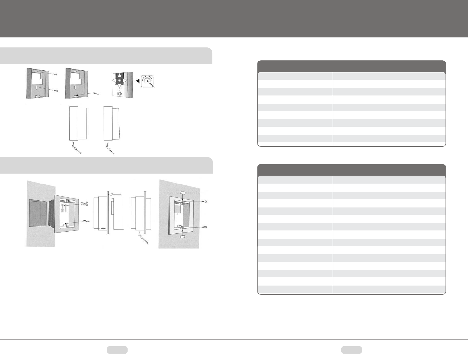
Surface Mount Installation
Tilt Holder
Normel
View
Upper
View
• Proper installtion height should be
determined at user’s discresion.
• The recomended height for camera
installation is 5’ from the ground.
• To allow for greater flexability a TILT
holder is supplied.
INDOOR MONITOR
Monitor
Scanning Frequency
Power
Power consumption
Resolution
Input signal
External jack, Input jack
Calling system
Dimensions (mm)
SPECIFICATIONS
4 Black & White Flat CRT
Horizontal 15.750 HZ (EIA) / 15.625HZ(CCIR)
Free voltage (AC 100V-240V,50/60 HZ)
13W(Activating), 2W(Stand by)
400 TV LINES
Composite Video 75 ohm 1Vp-p
Terminal Screw
2 Strokes (Ding Dong)
180(W)x220(H)x52(D)
Flush Mount Installation
1. Securly install the flush mount bracket using the spacers and screws provided. Check
that the bracket is both flat against the wall and level.
2. Place the camera unit into the bracket starting with the top, then carefully push in the
lower portion of the unit into position.
3. Once proper positioning has been achieved, remove the camera screw cover and mark the
screw position on the wall.
4. Remove the camera unit from the bracket and screw spacer into the camara mounting
screw hole. Be sure to use the correct diameter screw.
5. Replace the camera unit into the wall bracket and tighten the camara screw. Replace the
screw cover, but do not over-tighten otherwise damage to the plastic casing will occur.
OUTDOOR CAMERA
CCD
SYNC system
Flame
Lens
Illumination
Power
Power consumption
Telephone call system
Signal system
Scanning system
Operating Temperature
Auto Iris
Microphone
Audio Amplifier
Dimensions (mm)
Black & White 1/3 CCD
Internal
30/sec
F=2 Fixed focus, 92 degree view angle
0.5 LUX at 400mm Distance
DC 12V
3W
2 WIRES
EIA / CCIR
525 LINES / 625 LINES
-10 50 (+14 122 )
Internal ALC System
Condense type
RX & TX
90(W)x120(H)x47(D)m
6
3
Page 4

Included Components
Base Unit Installation
Indoor Monitor
Handset
Switch
Contrast
Volume
Speaker
Outdoor Camera
AC Power Input
Camera Filter
CCD Camera Lens
Speaker
Monitor
Screen
Door Release
Monitor Activation
Power Indicator
Wall
Mount
Bracket
Cable Connections
When installing this video intercom system take care to connect the cables as follows:
1. Peel back the grey outer covering of the cable to expose the Red and White wires, strip
back the colored plastic by approximately 10mm to exposed wire.
2. Following the wiring diagram below, connect the Red line to the terminal marked 1R; the
white line to the terminal marked 2W ; the any color cable of the recommended diameter
can be used but make sure the same color is connected to the corresponding terminals
on the camera and the monitor.
3. If the electric door strike option is be used, connect the Door Open Key to terminals
as shown below. Door Open Key maximum DC 12 voltage 250mA.
1~50m : 0.65
50~100m : 1.0
Indoor
Base Unit
AC Adaptor
Door Strike
DC 12V/250mA
Outdoor
Camera
Microphone
Mounting Hardware
Call Button
Surface
Mount
Bracket
Flush Mount Bracket
Monitor Installation
• Securely install the wall mount bracket using the supplied screws ( 4X32 )
• With the wall bracket securely fixed to the wall, place the indoor monitor firmly against the
bracket and push down the indoor unit on the bracket
4 5
 Loading...