

Vitek SAGA ST-H, SAGA ST-H Series, SAGA VT-ST1640H, SAGA VT-ST840H, SAGA VT-ST440H User Manual
Page 1

4, 8, and 16 Channel Digital Video
Recorders with H.264 Compression
VITEK
• H.264 Compression
• 240 IPS Recording with live Viewing
• Up to 4 Terabyte Internal Storage (4x - 1TB HDD) and Up to 40 Terabytes External
Storage (4x - 10 HDD Expansion bay units)
• 4 Channel Audio
SAGA “ST-H” Series
• Remote Viewing with 2-way Audio Communication over the internet
• Multi-site remote client
• Built-in DVD/RW drive
• Accepts 4 External (VT-XHD10) HDD Bays for an Additional 40 Hard Drives
• Block Search Function Retrieves Lost Files, Even from Damaged Hard Drives
• Embedded Linux OS
• Dynamic IP support (DDNS)
• Average File Size of 1~3KB(CIF), 3~7KB(D1/2), 6~15KB(D1)
• Continuous, Motion, Alarm, V-Loss, Scheduled recording modes
• Numerous search modes: Calendar, Search & Copy, Time, Event, Block, File,
Bookmark & Log
• Notification e-mail to up to 10 accounts on Motion, Alarm, V-Loss, HDD Fail
• Pentaplex Plus: Record, Playback, Network Transmission, Mirror, Backup and Live
Viewing
• Backup to External HDD, CD-R, DVD-RW, DVD+RW, USB Memory Stick
• Control up to 16 DVRs via Keyboard or IR Remote control
Page 2

SAGA “ST-H” Series
1
PACKAGE CONTENTS
Prior to installation of a SAGA ST-H Series DVR, please verify that the packaging
contains the following contents:
1. One DVR
2. One AC Adaptor
3. One Power Cable
4. One Remote Controller
5. DVR Viewer Program CD
6. This Instruction Manual.
7. Two AAA batteries.
8. Rack Mount Ears and screws.
If any of the contents are missing, please contact the Distributor immediately.
Page 3
SAGA “ST-H” Series
2
RISK OF ELECTRICAL SHOCK WARNING
Disposal of Old Electrical & Electronic Equipment
(Applicable in the European Union and other European countries
with separate collection systems)
This symbol on the product or on its packaging indicates that this product shall not
be treated as household waste. Instead it shall be handed over to the applicable
collection point for the recycling of electrical and electronic equipment. By ensuring
this product is disposed of correctly, you will help prevent potential negative
consequences for the environment and human health, which could otherwise be
caused by inappropriate waste handling of this product. The recycling of materials
Page 4

SAGA “ST-H” Series
3
will help to conserve natural resources. For more detailed information about
recycling of this product, please contact your local city office, your household waste
disposal service or the shop where you purchased the product.
DISCLAIMER
While every effort has been made to ensure that the information contained in this
guide is accurate and complete, no liability can be accepted for any errors or
omissions.
Vitek reserves the right to change the specifications of the hardware and software
described herein at any time without prior notice.
No part of this guide may be reproduced, transmitted, transcribed, stored in a
retrieval system, or translated into any language in any form, by any means, without
prior written permission of Vitek.
Vitek makes no warranties for damages resulting from corrupted or lost data due to
a mistaken operation or malfunction of the Digital Video Recorders, the software,
personal computers, peripheral devices, or unapproved/unsupported devices.
Trademark Acknowledgements
VT-ST1640H/ST840H/ST440H Digital Video Recorders are trademarks of Vitek.
Other names and products not mentioned here may be registered trademarks or
trademarks of their respective companies.
Page 5

SAGA “ST-H” Series
4
FCC NOTICE
Digital Video Recorders, VT-ST1640H, VT-ST840H, VT-ST440H
These devices comply with Part 15 of the FCC Rules. Operation is subject to the
following two conditions;
1. These devices may not cause harmful interference, and
2. These devices must accept any interference received, including interference that
may cause undesired operation.
Note: This equipment has been tested and found to comply with the limits for
Class B digital devices, pursuant to Part 15 of the FCC rules. These limits are
designed to provide reasonable protection against harmful interference in a residential
installation. These equipments generate, use and can radiate radio frequency energy
and, if not installed and used in accordance with the instructions, may cause harmful
interference to radio communications. However, there is no guarantee that
interference will not occur in a particular installation. If this equipment does cause
harmful interference to radio or television reception, which can be determined by
turning the equipment off and on, the user is encouraged to try to correct the
interference by one or more of the following measures:
• Reorient or relocate the receiving antenna.
• Increase the separation between the equipment and receiver.
• Connect the equipment to an outlet on a circuit different from that to which the
receiver is connected.
• Consult the dealer or an experienced technician for help.
Do not make any changes or modifications to the equipments unless otherwise
specified in the manual. If such changes or modifications should be made, you
could be required to stop operation of the equipment.
Page 6

SAGA “ST-H” Series
5
Read this First
Test Sessions
Before you try to record important subjects, we highly recommend that you make
several test sessions to ensure that the Digital Video Recorder is operating and
being operated correctly. Please note that Vitek, its subsidiaries and affiliates, and
its distributors are not liable for any consequential damages arising from any
malfunction of the Digital Video Recorder or its accessories.
The Privacy act
Please note that the Digital Video Recorders are intended for surveillance use and
should never be used in a manner that invades other people’s privacy or contravenes
international or domestic privacy act and its regulations. Please be advised that in
certain cases the monitoring of individuals, private properties, or commercial
properties may contravene legal rights of such individuals even if the images were
recorded for personal use.
Warranty Limitations
This equipment’s warranty is only effective in the country of sale. If a problem
arises while the Digital Video Recorder is in use abroad, please convey it back to
the country of sale before proceeding with a warranty claim to Vitek.
Page 7

SAGA “ST-H” Series
6
SAFETY PRECAUTIONS
Before using the Digital Video Recorder, please ensure that you read and
understand the safety precautions described below. Always ensure that the Digital
Video Recorder is operated correctly.
The safety precautions noted on the following pages are intended to instruct you in
the safe and correct operation of the Digital Video Recorder and its accessories to
prevent injuries or damage to the self, other persons and equipment.
In this Instruction Manual, the term “Digital Video Recorder”, “equipment” and
“device” refers primarily to the Digital Video Recorder and its accessories such as
power supply and its remote controller.
WARNINGS
Do not cover the ventilation opening or slots on the outer casing. To prevent the
Digital Video Recorder from overheating, provide at least two inches of air space
around the vent and the slots.
Do not drop metallic parts through slots. This could permanently damage the
Digital Video Recorder. Immediately turn the Digital Video Recorder’s power off
or unplug the power cord from the power outlet. Contact a qualified service
personnel authorized by the equipment distributor or the Vitek.
Do not attempt to disassemble or alter any part of the equipment that is not
expressly described in this guide. Disassembly or alteration may result in high
voltage electrical shock. Internal inspections, alterations and repairs should be
conducted by qualified service personnel authorized by the equipment distributor or
the Vitek.
Stop operation of the equipment immediately if it emits smoke or noxious fumes.
Failure to do so may result in fire or electrical shock. Immediately turn the Digital
Video Recorder’s power off, remove the power cable from the power outlet.
Confirm that smoke and fume emissions have ceased. Please consult the Digital
Video Recorder reseller.
Stop operation of the equipment if a heavy object is dropped or the casing is
damaged. Do not strike or shake. Failure to do so may result in fire or electrical
shock. Immediately turn the Digital Video Recorder’s power off or unplug the
power cord from the power outlet. Please consult the Digital Video Recorder
reseller.
Do not allow the equipment to come into contact with, or become immersed in,
water or other liquids. Do not allow liquids to enter the interior. The Digital
Video Recorder has not been waterproofed. If the exterior comes into contact with
liquids or salt air, wipe it dry with a soft, absorbent cloth. In the event that the
Page 8

SAGA “ST-H” Series
7
water or other foreign substances enter the interior, immediately turn the Digital
Video Recorder’s Power off or unplug the power cord from the power outlet.
Continued use of the equipment may result in fire or electrical shock. Please consult
the Digital Video Recorder reseller.
Do not use substances containing alcohol, benzene, thinners or other flammable
substances to clean or maintain the equipment. The use of these substances may
lead to fire. Use a dry cloth on a regular periodic basis and wipe away the dust
and dirt that collects on the device. In dusty, humid or greasy environments, the
dust that collects around the ventilation or the slots on the outer casing over long
periods of time may become saturated with humidity and short-circuit, leading to
fire.
Do not cut; damage, alter or place heavy items on the power cord. Any of these
actions may cause an electrical short circuit, which may lead to fire or electrical
shock.
Do not handle the device or power cord with wet hands. Handling it with wet hands
may lead to electrical shock. When unplugging the cord, ensure that you hold the
solid portion of the plug. Pulling on the flexible portion of the cord may damage
or expose the wire and insulation, creating the potential for fires or electrical shocks.
Use only the recommended power accessories. Use of power sources not
expressly recommended for this equipment may lead to overheating, damage of the
equipment, fire, electrical shock or other hazards.
The supplied power supply and power cord are designed for exclusive use with the
Digital Video Recorder. Do not use it with other products or battery. There is a
risk of fire and other hazards.
Avoid using, placing or storing the equipment in places subject to strong sunlight or
high temperatures, such as a greenhouse or trunk of a car. High temperatures may
also cause deformation of the casing. Ensure that there is good ventilation when
using the equipment.
Do not operate the Digital Video Recorder beyond its specified temperature,
humidity or power source ratings. Do not use the Digital Video Recorder in an
extreme environment such as in high temperature or high humidity. Use the
device at temperatures within 0~+40 (32°F~104°F) and humidity below 90%.
PREVENTING MALFUNCTION
Avoid Strong Magnetic Fields. Never place the Digital Video Recorder in close
proximity to electric motors or other equipment generating strong electromagnetic
fields. Exposure to strong magnetic fields may cause malfunctions or corrupt
image data.
Page 9

SAGA “ST-H” Series
8
Avoid Condensation Related Problems. Moving the equipment rapidly between
hot and cold temperatures may cause condensation (water droplets) to form on its
external and internal surfaces. You can avoid this by placing the equipment in an
airtight, re-sealable plastic bag and letting it adjust to temperature changes slowly
before removing it from the bag.
If Condensation forms inside the Digital Video Recorder. Stop using the
equipment immediately if you detect condensation. Continued use may damage
the equipment. Remove the power cord from the power outlet and wait until the
moisture evaporates completely before resuming use.
Page 10

SAGA “ST-H” Series
9
Table of Contents
PACKAGE CONTENTS……………………………………………….…………………………………………………………….. 1
RISK OF ELECTRICAL SHOCK WARNING……………………………………………………………………………………. 2
DISCLAIMER………………………………………………………………………………………………………………………….. 3
FCC NOTICE…………………………………………………………………………………………………………………………. 4
READ THIS FIRST…………………………………………………………………………………………………………………… 5
TEST SESSIONS……………………………………………………………………………………………………………………… 5
THE PRIVACY ACT………………………………………………………………………………………………………………….. 5
WARRANTY LIMITATIONS…………………………………………………………………………………………………………. 5
SAFETY PRECAUTIONS……………………………………………………………………………………………………………. 6
WARNINGS……………………………………………………………………………………………………………………………. 6
PREVENTING MALFUNCTION…………………………………………………………………………………………………… 7
TABLE OF CONTENTS……………………………………………………………………………………………………………… 9
I. FEATURES & SPECIFICATIONS………………………………………………………………………………………………. 13
1.1 Features……………………………………………………………………………………………………………………………. 13
1.2 Specifications……………………………………………………………………………………………………………………… 14
II. OVERVIEW & CONTROLS………………………………………………………………………………………………….... 17
2.1 Front Panel………………………………………………………………………………………………………………………... 17
2.2 Rear Panel…………………………………………………………………………………………………………………………. 20
2.3 Remote Control…………………………………………………………………………………………………………………… 22
2.4 Mouse Control…………………………………………………………………………………………………………………….. 23
III.INSTALLATION AND CONNECTIONS……………………………………………………………………………………….. 24
3.1 CONNECTION LAYOUT………………………………………………………………………………………………………... 24
3.2 XHD-10U………………………………………………………………………………………………………………………….. 25
3.3 EXTERNAL TERMINAL CONNECTION…………………………………………………………………………………... 26
3.3.1 RS-485……………………………………………………………………………………………………………………….. 26
3.3.2 TIME ADJUST……………………………………………………………………………………………………………… 26
3.3.3 RELAY OUTPUT………………………………………………………………………………………………………… 27
3.3.4 ALARM SENSOR INPUT…………………………………………………………………………………………………. 27
3.3.5 VGA PIN LAYOUT………………………………………………………………………………………………………. 28
3.3.6 RS-232C PIN LAYOUT…………………………………………………………………………………………………. 28
IV .BASIC OPERATION……………………………………………………………………………………………………………... 29
4.1 MAIN SCREEN…………………………………………………………………………………………………………………… 29
4.2 STATUS SCREEN………………………………………………………………………………………………………………… 30
4.3 NETWORK STATUS…………………………………………………………………………………………………………….. 32
4.4 RECORDING BITRATE…………………………………………………………………………………………………………. 33
4.5 LIVE VIEW………………………………………………………………………………………………………………………… 34
4.5.1 LIVE VIEW MODE SEQUENCE……………………………………………………………………………………… 34
4.5.1.1 VT-ST1640H……………………………………………………………………………………………………………. 34
4.5.1.2 VT-ST840H……………………………………………………………………………………………………………... 35
4.5.2 FULL SCREEN DISPLAY………………………………………………………………………………………………. 35
4.5.3 AUTOMATIC SEQUENCE………………………….............................................................................................. 36
4.6 FREEZE……………………………………………………………………………………………………………………………. 37
4.6.1 SINGLE SCREEN VIEW MODE…………………………………………………………………………………………… 37
4.7 ZOOM…………………………………………………………………………………………………………………………….. 38
4.8 PICTURE-IN-PICTURE……………………………….................................................................................................... 39
4.9 SPOT MONITOR…………………………………………………………………………………………………………………. 40
4.10 BASIC RECORDING…………………………………………………………………………………………………………… 40
4.11 BASIC PLAYBACK…………………………………………………………………………………………………………….. 47
4.11.1 PLAY/REVERSE PLAY/PAUSE/STOP………………………………………………………………………………… 47
Page 11

SAGA “ST-H” Series
10
4.11.2 FAST FORWARD/REWIND…………………………………………………………………………………………... 48
4.11.2.1 JOG SHUTTLE…………………………………………………………………………………………………… 48
4.11.2.2 FAST/DIRECTION……………………………………………………………………………………………….. 48
4.11.3 PICTURE-IN-PICTURE…………………………………………………………………………………………………….. 49
4.11.4 SLOW…………………………………………………………………………………………………………………………… 50
4.11.5 LOOP PLAYBACK…………………………………………………………………………………………………………… 50
4.11.6 BOOKMARK………………………………………………………………………………………………………………….. 51
4.11.7 AUDIO PLAYBACK………………………………………………………………………………………………………….. 52
V. ADVANCED OPERATION………………………………………………………………………………………………………. 53
5.1 BACK UP………………………………………………………………………………………………………………………….. 53
5.1.1 CD-RW / DVD-RW / DVD+RW / DVD RAM……………………………………………………………………… 53
5.2 COPY STATUS……………………………………………………………………………………………………………………. 56
5.3 RECOMMENDED BRANDS……………………………………………………………………………………………………. 57
5.4 PAN / TILT / ZOOM CAMERA CONTROL……………………………………………………………………………….. 58
5.4.1 BASIC PAN / TILT / ZOOM CONTROL…………………………………………………………………………… 58
5.4.2 CREATING AND MOVING TO PRESET POINTS…………………………………………………………………. 58
VI. ADVANCED RECORDING……………………………………………………………………………………………………... 59
6.1 ALARM RECORDING…………………………………………………………………………………………………………..
59
6.2 VIDEO LOSS RECORDING………………………………………………………………………………………………… 60
6.3 MOTION RECORDING……………………………………………………………………………………………………….. 61
VII. MAIN MENU…………………………………………………………………………………………………………………….. 62
7.1 QUICK SETUP…………………………………………………………………………………………………………………… 63
7.1.1 QUICK SETUP…………………………………………………………………………………………………………... 63
7.1.2 IMAGE SIZE……………………………………………………………………………………………………………… 63
7.1.3 RECORD FRAME……………………………………………………………………………………………………….. 63
7.1.4 IMAGE QUALITY………………………………………………………………………………………………………….. 64
7.1.5 EVENT…………………………………………………………………………………………………………………….. 64
7.1.6 PRE RECORD TIME……………………………………………………………………………………………………. 64
7.1.7 POST RECORD TIME…………………………………………………………………………………………………….. 64
7.1.8 PREVIEW QUALITY………………………………………………………………………………………………………. 64
7.1.9 AUDIO RECORD………………………………………………………………………………………………………... 65
7.1.10 REMOTE CONTROL ID………………………………………………………………………………………………. 65
7.1.11 SAVE……………………………………………………………………………………………………………………... 65
7.2 SCREEN …………………………………………………………………………………………………………………………... 65
7.2.1 AUTO SEQUENCE……………………………………………………………………………………………………… 66
7.2.2 DISPLAY …………………………………………………………………………………………………………………. 67
7.2.2.1 HDD FREE SPACE………………………………………………………………………………………………..
67
7.2.2.2 HDD FREE SPACE MODE………………………………………………………………………………………
68
7.2.2.3 RECORD STATUS………………………………………………………………………………………………….
68
7.2.2.4 CLOCK DISPLAY………………………………………………………………………………………………….
68
7.2.2.5 DATE & TIME MODE…………………………………………………………………………………………….
68
7.2.2.6 TITLE DISPLAY……………………………………………………………………………………………………
69
7.2.2.7 TITLE MODE……………………………………………………………………………………………………….
69
7.2.2.8 BORDER COLOR………………………………………………………………………………………………….
69
7.2.2.9 REMOTE COMTROL ID………………………………………………………………………………………….
69
7.2.3 TITLE ……………………………………………………………………………………………………………………….. 69
7.2.4 MULTI SCREEN ………………………………………………………………………………………………………… 71
7.2.5 COVERT ………………………………………………………………………………………………………………….. 71
Page 12

SAGA “ST-H” Series
11
7.2.6 SPOT ……………………………………………………………………………………………………………………… 72
7.2.6.1 SPOT MODE……………………………………………………………………………………………………….. 72
7.2.6.2 SPOT SEQ. TIME………………………………………………………………………………………………….. 72
7.2.6.3 VIDEO LOSS SKIP………………………………………………………………………………………………… 73
7.2.7 CAMERA …………………………………………………………………………………………………………………. 73
7.3 RECORD ………………………………………………………………………………………………………………………….. 73
7.3.1 RECORD SETUP………………………………………………………………………………………………………… 74
7.3.2 RECORD PROGRAM …………………………………………………………………………………………………….. 75
7.3.3 PREVIEW QUALITY………………………………………………………………………………………………………. 77
7.3.4 AUDIO RECORD………………………………………………………………………………………………………... 78
7.3.5 REPEAT RECORD ……………………………………………………………………………………………………… 78
7.3.6 BACKUP MODE ………………………………………………………………………………………………………….. 78
7.3.7 HOLIDAY ………………………………………………………………………………………………………………… 79
7.3.8 RECORD LIMIT…………………………………………………………………………………………………………. 79
7.4 EVENT …………………………………………………………………………………………………………………………….. 80
7.4.1 MOTION DETECTION…………………………………………………………………………………………………. 80
7.4.1.1 CHANNEL………………………………………………………………………………………………………….. 81
7.4.1.2 SENSITIVITY……………………………………………………………………………………………………….. 81
7.4.1.3 AREA SETUP………………………………………………………………………………………………………. 81
7.4.1.4 TEST MOTION…………………………………………………………………………………………………….. 81
7.4.2 EVENT SCREEN MODE ………………………………………………………………………………………………. 81
7.4.3 EVENT CHECK …………………………………………………………………………………………………………. 82
7.4.4 EVENT MESSAGE………………………………………………………………………………………………………. 82
7.4.5 EVENT MESSAGE RESET …………………………………………………………………………………………….. 82
7.4.6 EVENT BUZZER ………………………………………………………………………………………………………… 82
7.4.7 SENSOR INPUT …………………………………………………………………………………………………………… 82
7.4.8 RELAY OUTPUT………………………………………………………………………………………………………… 83
7.5 SYSTEM …………………………………………………………………………………………………………………………… 84
7.5.1 HDD……………………………………………………………………………………………………………………….. 85
7.5.1.1 HDD CONFIGURATION………………………………………………………………………………………… 85
7.5.1.2 REC HDD INITIALIZE…………………………………………………………………………………………… 86
7.5.1.3 BACK UP HDD INITIALIZE…………………………………………………………………………………….. 86
7.5.2 CLOCK …………………………………………………………………………………………………………………… 87
7.5.2.1 DATE & TIME……………………………………………………………………………………………………… 87
7.5.2.2 TIME ADJUST……………………………………………………………………………………………………... 88
7.5.3 VIDEO STANDARD……………………………………………………………………………………………………….. 88
7.5.4 LANGUAGE ……………………………………………………………………………………………………………... 89
7.5.5 REMOTE CONTROL ID………………………………………………………………………………………………... 89
7.5.6 KEY ECHO ………………………………………………………………………………………………………………. 89
7.5.7 ADVANCED SETUP ……………………………………………………………………………………………………. 89
7.5.7.1 PASSWORD CHECK……………………………………………………………………………………………… 90
7.5.7.2 SET PASSWORD…………………………………………………………………………………………………... 90
7.5.7.3 USER AUTHORITY……………………………………………………………………………………………….. 91
7.5.7.4 DVR MENU SETUP……………………………………………………………………………………………….. 91
7.5.7.4.1 MENU INITIALIZE………………………………………………………………………………………….. 92
7.5.7.4.2 LOAD MENU FROM FILE………………………………………………………………………………… 92
7.5.7.4.3 SAVE MENU TO FILE……………………………………………………………………………………… 93
Page 13

SAGA “ST-H” Series
12
7.5.8 FIRMWARE UPGRADE………………………………………………………………………………………………... 93
7.6 LINK………………………………………………………………………………………………………………………………... 94
7.6.1 NETWORK ……………………………………………………………………………………………………………….. 94
7.6.1.1 DHCP……………………………………………………………………………………………………………….. 95
7.6.1.2 IP ADDRESS……………………………………………………………………………………………………….. 95
7.6.1.3 SUBNET MASK……………………………………………………………………………………………………. 95
7.6.1.4 GATEWAY………………………………………………………………………………………………………….. 95
7.6.1.5 DNS………………………………………………………………………………………………………………….. 95
7.6.1.6 PORT………………………………………………………………………………………………………………… 96
7.6.1.7 DYNAMIC IP SERVER……………………………………………………………………………………………. 96
7.6.1.8 BACKUP IP SERVER………………………………………….…………………………………………………. 96
7.6.2 RS232C……………………………………………………………………………………………………………………. 96
7.6.3 RS485……………………………………………………………………………………………………………………… 97
7.6.4 PTZ………………………………………………………………………………………………………………………… 97
7.6.5 E-MAIL……………………………………………………………………………………………………………………. 98
7.6.5.1 SEND EMAIL………………………………………………………………………………………………………. 99
7.6.5.2 SMTP SERVER…………………………………………………………………………………………………….. 99
7.6.6 DVR NAME……………………………………………………………………………………………………………….. 99
7.6.7 DVR LOCATION ………………………………………………………………………………………………………... 100
7.7 SEARCH…………………………………………………………………………………………………………………………… 100
7.7.1 CALENDER SEARCH…………………………………………………………………………………………………... 101
7.7.2 SEARCH & COPY……………………………………………………………………………………………………….. 101
7.7.3 TIME SEARCH…………………………………………………………………………………………………………… 102
7.7.4 EVENT SEARCH…………………………………………………………………………………………………………… 103
7.7.5 BLOCK SEARCH………………………………………………………………………………………………………… 104
7.7.6 FILE SEARCH……………………………………………………………………………………………………………. 104
7.7.7 BOOKMARK SEARCH……………………………………………………………………………………………………. 105
7.7.8 TEXT SEARCH…………………………………………………………………………………………………………… 105
7.7.9 LOG FILE ………………………………………………………………………………………………………………….. 105
7.8 COPY ……………………………………………………………………………………………………………………………… 106
7.8.1 COPY………………………………………………………………………………………………………………………… 107
7.8.2 COPY STATUS………………………………………………………………………………………………………….. 108
7.8.3 MEDIA FORMAT………………………………………………………………………………………………………….. 108
7.9 EXIT………………………………………………………………………………………………………………………………… 109
8. CLIENT PROGRAM: DVR VIEWER ……………………………………………………………………………………… 110
8.1 SYSTEM REQUIREMENT…………………………………………………………………………………………………… 110
8.2 INSTALLING THE DVR VIEWER……………………………………………………………………………………….. 110
8.3 DVR VIEWER - LAYOUT………………………………………………………………………………………………….. 113
8.4 DVR VIEWER - LIVE MODE…………………………………………………………………………………………….. 131
8.5 DVR VIEWER – PLAYBACK MODE ………………………………………………………………………………….. 133
8.5.1 TIME SEARCH………………………………………………………………………………………………………….. 134
8.5.2 CALENDAR SEARCH…………………………………………………………………………………………………….. 135
8.5.3 EVENT………………………………………………………………………………………………………….. 136
8.5.4 TEXT………………………………………………………………………………………………………….. 137
8.5.5 BLOCK………………………………………………………………………………………………………….. 139
8.6 DVR PLAYER – SETUP………………………………………………………………………………………………….. 141
8.6.1 QUICK SETUP………………………………………………………………………………………………………….. 142
8.6.2 SCREEN………………………………………………………………………………………………………….. 143
8.6.2.2 Display………………………………………………………………………………………………………….. 143
Page 14

SAGA “ST-H” Series
13
8.6.2.3 Title………………………………………………………………………………………………………….. 144
8.6.2.4 Multi-screen………………………………………………………………………………………………………….. 145
8.6.2.5 Covert………………………………………………………………………………………………………….. 145
8.6.2.6 Spot………………………………………………………………………………………………………….. 145
8.6.2.7 Camera………………………………………………………………………………………………………….. 146
8.6.3 RECORD………………………………………………………………………………………………………….. 146
8.6.3.1 Record………………………………………………………………………………………………………….. 146
8.6.3.2 Record Program………………………………………………………………………………………………………….. 146
8.6.3.3 Holiday………………………………………………………………………………………………………….. 147
8.6.4 EVENT………………………………………………………………………………………………………….. 147
8.6.4.1 Event………………………………………………………………………………………………………….. 147
8.6.4.2 Motion Detection……………………………………………………………………………………………………….. 148
8.6.4.3 Sensor Input………………………………………………………………………………………………………….. 148
8.6.4.4 Relay Output………………………………………………………………………………………………………….. 149
8.6.5 SYSTEM………………………………………………………………………………………………………….. 149
8.6.5.1 System………………………………………………………………………………………………………….. 149
8.6.5.2 HDD………………………………………………………………………………………………………….. 149
8.6.5.3 CLOCK………………………………………………………………………………………………………….. 150
8.6.5.4 ADVANCED SETUP…………………………………………………………………………………………………….. 150
8.6.6 LINK………………………………………………………………………………………………………….. 150
8.6.6.1 Network………………………………………………………………………………………………………….. 150
8.6.6.2 RS-232C………………………………………………………………………………………………………….. 151
8.6.6.3 RS-485………………………………………………………………………………………………………….. 151
8.6.6.4 PTZ………………………………………………………………………………………………………….. 151
8.6.6.5 E-mail………………………………………………………………………………………………………….. 152
8.6.7 DOWNLOAD………………………………………………………………………………………………………….. 152
8.6.7.1 DVR Logo Select……………………………………………………………………………………………………….. 152
8.6.7.2 Firmware Download…………………………………………………………………………………………………….. 152
I. FEATURES & SPECIFICATIONS
1.1
Features
VT-ST1640H/ST840H/ST440H Series DVR has the following features:
• H.264 16CH/8CH/4CH Stand-Alone DVR Series.
• Max. 240ips recording.
• Pentaplex Function: Playback, recording, Backup, Copy and Remote Network
transmission simultaneously.
• Network Viewer: 16 units X 16 Clients (16 Clients can connect at the same time).
• E-mail notification for events.
• AVI file conversion with network viewer.
• Ease of operation :Mouse, Remote Controller, DVR controller through Network
viewer,
External Keyboard Controller, Front Panel.
• Web browser support.
• Quick setup.
• Individual settings per channel.
• Two way audio over the network.
• Copy: USB memory stick, CD R, CD RW, DVR+RW, DVD-RW, DVR RAM.
Page 15
SAGA “ST-H” Series
14
• Built-in File viewer on copied media.
• Search: Calendar, Time, Event, Block, Bookmark, Text, Log file.
• Time synchronization: Internet time adjustment, Time trimming manually, Daylight
savings time.
• POS support with easy text string search.
• Digital watermark support.
• Data recovery.
• Optional CD RW/DVD RW.
• CMS (Central Management software): Max. 64CH display and infinite number of
DVR management.
• Mirroring backup (Built-in data redundancy) and Event backup.
• HDD expansion bay: Expands max. 40 HDD’s (40 TB).
• Installs max. 4 SATA HDD’s
• 4CH Audio inputs.
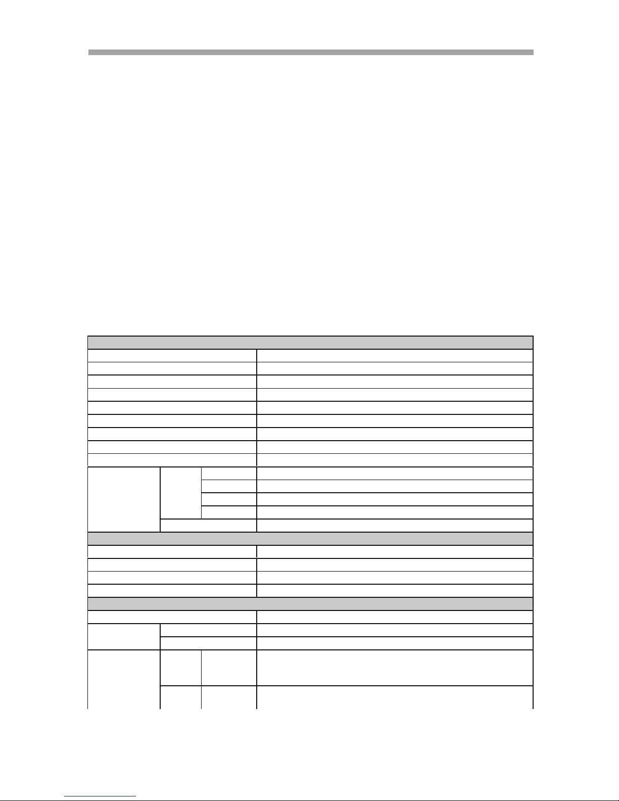
1.2 Specifications
MODEL NO: VT-ST1640H / VT-ST840H / VT-ST440H
Video
Video Input 16CH/ 8CH/ 4CH (BNC)
Input Level 1.0Vp-p±10% Composite, 75 Balanced
Loop Through Output 16 CH/8 CH/4 CH (BNC)
Video Standard NTSC, PAL, AUTO
Main Monitor Output 1.0 V p-p Composite, 75 Balanced
Analog Spot Monitor Output 1.0 V p-p Composite, 75 Balanced
Camera Name Max. 8 Characters
Screen Split Control 1, 4, 6, 7, 9, 10, 13, 16 Screen
Screen Rotate Control 1~60 Seconds
Display 720(H) NTSC 720(H) 480(V)
480(V) PAL 720(H) 576(V)
Speed NTSC 480 / 240 / 120 frames(Every CH Real Time)
PAL 400 / 200 / 100 frames(Every CH Real Time)
Function Auto sequence 1, 4, 6, 7, 9, 10, 13, 16 Split, PIP
Audio
Compression ADPCM
Audio Input(Line)
4CH (RCA)
Input Level 0.5~1.4Vp-p@20k
Audio Output(Line) 1CH (RCA)
Recording
Compression
H.264
Resolution NTSC 720(H) 480(V), 720(H) 240(V), 340(H) 240(V)
PAL
720(H) 576(V), 720(H) 288(V), 340(H) 288(V)
Speed NTSC 340 x240
Max. 240/ 240/ 120Images(CIF)
720 x240 Max.120/ 120/ 120 Images(Half D1)
720 x480 Max. 60/ 60/ 60 Images(D1)
PAL 340 x288
Max. 200/ 200/100 Images(CIF)
720 x288 Max. 100/ 100/ 100 Images(Half D1)
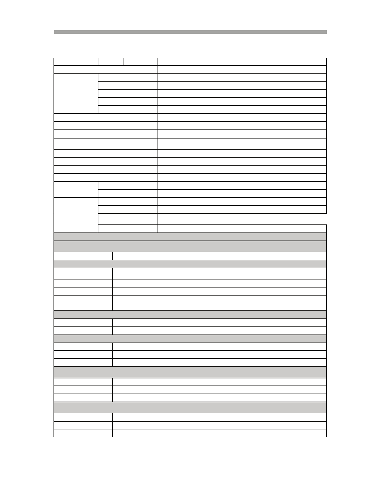
Page 16
SAGA “ST-H” Series
15
720 x576 Max. 50/ 50/ 50 Images(D1)
Duplexer or Triplexer Pentaplex
Each CH Frame Setting Available
Event, Normal Available
Speed Available
Resolution Available
Quality Changed at 4 level(Low, Normal, Fine, Superfine)
Setup per Channel Individual
Record limit Automatic data delete for privacy
Data Size 1~3KB(CIF), 3~7KB(D1/2), 6~15KB(D1)
Recording Mode Normal(Continuous),Event( Motion detection, Sensor, Video loss), Schedule,
Holiday
Pre-Alarm 5 Seconds
Watermark Support
Schedule 24 groups per day by an hour, Holidays are same as Sunday
Summer Time Support
HDD Internal Storage
4 HDD’s (1TB x 4)
Speed 7200RPM
DMA 45MHz DMA
Type
SATA compatible
External Storage Max. 40 HDD’s ( External Bay ( 10
HDD’s) x 4)
HDD Bay Interface USB 2.0
Searching & Playback
Searching Method Time, Calendar, Event,(Copied)File, Text ,
Block
Playback(Reverse) 1, 2, 4, 16, 32, 64, 128 velocity 1/2, 1/4, 1/16, 1/32, 1/64, 1/128
Copy Device
Internal
CD/DVD RW
Internal CD/DVD RW (SATA)
Media Support CD R/ CD RW/DVD RW/ DVD RAM
USB 2.0 USB(2.0) memory stick
Copied File Compatibility
with PC (Windows)
Compatible
Backup
Digital Backup Internal HDD, External HDD Bay
Backup Method Mirroring, Event
Alarm
Sensor Input
16CH/8CH /4CH (Terminal)
Alarm Output
4 Relay out (Programmable, NO: Normal Open), Terminal
Motion Detection
Available For Each Camera Multi-Detection Level
Multi-Remote
Surveillance
Monitoring Environment Client Software, Central Monitoring System, Web browser
Transmission Rate Approx. 120ips(CIF) Full Motion Transmission(16 Clients accessible
Search
Supporting Multi-Client(16 Clients accessible)
System Monitoring &
Recovery
System Logging
Power Failure Checkable/Menu Change/Network connect
Monitoring
Software Watchdog
Recovery
Auto-Reboot By Watchdog Automatic Database Recovery
Page 17

SAGA “ST-H” Series
16
Connector
Others
OS Embedded Linux
Language(13
kinds)
English, Korean, Japanese, Polish ,Spanish, Russian, Chinese, Taiwanese,
French, Turkish, German, Italian, Portuguese.
ATM Interface Diebold ATM Support
POS Interface AVE POS Support
Control Device Front key, Remote controller, Mouse(PS/2),External Keyboard,
PTZ(16 kinds) SPD (Samsung Techwin),SRX (Samsung Techwin),SCC-643(Samsung
Electronics)
SD-290 (Smile CAM),CS-854A(Panasonics),LPT-A100L
DSC-230S (Dongyang Unitech),SK-D106(Sunkwang),VC-C4R(Canon)
PELCO P-TYPE (Pelco),PELCO D-TYPE (Pelco),
TK-C655/676 (JVC),DMP23(DAIWA),BOSCH
PCS-SERIES,EZ PROTOCOL(Vitek)
Number of Event list / Log
list
100,000 / 100,000 per HDD
Video Input 16CH/8CH /4CH (BNC)
Loop Though
Output
16CH/8CH /4CH (BNC)
Main Monitor Output Composite (BNC 1 Port(Rear) ,S-
Video( Not Supported) ,VGA
Output( Selectable C-video or
VGA (VESA) /3D VGA(Option)
4 pins mini DIN( S-Video)
Spot Monitor Output BNC 1 Port
Audio Input (Mono) 16CH/8CH/4CH Line Input (RCA)
Audio Output ( Mono) 1CH Line Output (RCA)
HDD Bay Connection USB 2.0 Connector
External Control ( RS-232C) Serial (9 pins Male DSUB)
Firmware Upgrade USB 2.0 Port, Network
Sensor Input 16/8/4CH ( Terminal Block)
(Include Ground Common 4 pins)
Alarm Output
4 Relay output 2 pins Terminal
Block (NO, Common) x 4=8P
(Total)
PTZ (RS-485) 2 pins Terminal Block , Half
Duplex
Ethernet RJ-45 , 10/100 Mbps
USB 2.0 Front 1 Port, Rear 2 ports
Electrical
Power Source DC 12V, 10A
Power Consumption Approx. 60 Watt ( Including 1 HDD)
Environmental
Operating Temp
0 ~ + 40
Storage
Temperature
-10 ~ + 60
Humidity
30 ~ 90%RH (non-condensing)
Physical
Construction Shape
Metal Case
Construction
Material
Metal Case
Page 18
SAGA “ST-H” Series
17
II. OVERVIEW & CONTROLS
This section provides the information about the front panel and rear panel.
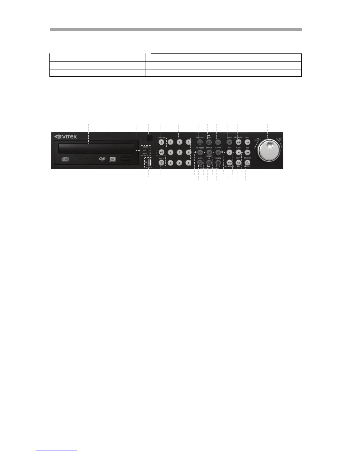
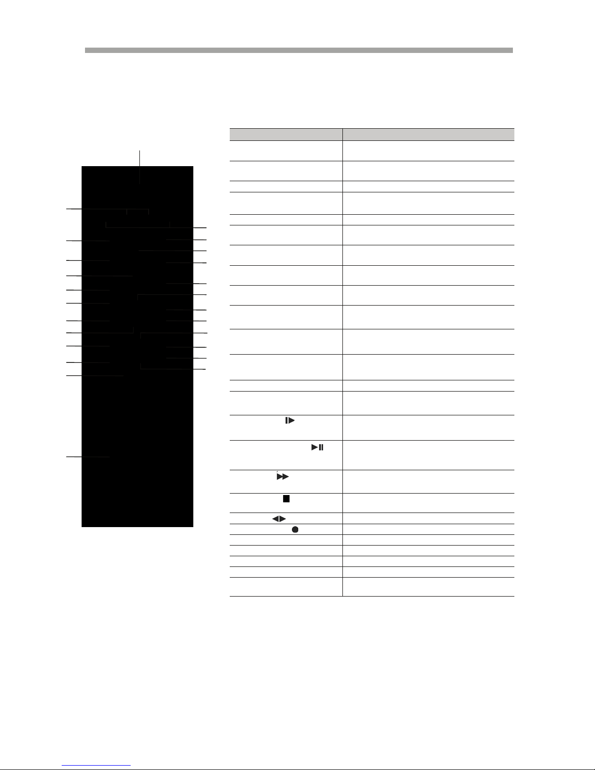
2.1 Front Panel
1. DVD-RW
A DVD-RW drive is installed in the front 5.25” expansions bay.
2. IR RECEIVER
Infrared signal receiver for the IR remote controller. Do not block the receiver
as a clear line of sight is required for proper operation.
3. STATUS LED
Displays the status of the DVR, (Standby), HDD read/write and network
transmission.
4. USB 2.0
The USB 2.0 port can be used to connect to numerous USB 2.0 backup devices
including XHD-10U external HDD add-on bays, external optical drives and USB
memory sticks.
5. AUDIO SELECT
This button selects the recorded audio channel.
AUDIO SEL button + Channel button
6. NUMERIC BUTTONS / CHANNEL SELECT
a) Selects a specific channel number to be displayed in full screen.
b) Enter the numeric password when prompted.
7. SPOT MONITOR / ESC
a) Activates the spot monitor control.
b) Returns to previous menu screen.
c) Exits from various function and menu screens.
Body Color
Black with Transparent White Gray Silicon Rubber Key
Dimension
430 (W) x 68(H) x 390 (D) mm
Weight
Approx 4.5Kgs
1
8
6
13
7
14
9
4
16
15 5 3 2 10
11
12
26
18
19
24
20
21
22
23
25
17
Page 19

SAGA “ST-H” Series
18
8. MENU / UP DIRECTIONAL BUTTON
a) Accesses the main menu screen.
b) Tilts up in PTZ mode.
c) Navigates up in the menu screen.
d) Moves the zoom box up in zoom mode.
9. FUNCTION
a) Used in conjunction with the “USER” option for Relay 4 of the alarm output.
b) Controls PTZ movement speed in PTZ mode.
10. LIVE / PLAYBACK
This button exits the playback mode and returns to the live monitoring mode.
Pressing this button once more will toggle between live and paused playback
mode.
11. PLAY / PAUSE
a) Starts the playback of recorded data. By default, the playback starts from the
earliest recording. If the recording has been played back, the playback will start
from where it was left off.
b) Toggles between playback and pause mode.
12. FAST
a) Fast forward. Press this button repeatedly to toggle between 2X normal playback
speed through 128X normal playback speed.
13. MULTI(DISPLAY)
This button is used to toggle between multiple display modes: 16 channel, 13
channel, 10 channel, 9 channel, 7 channel, 6 channel and 4 channel split screen
display modes.
14. ALARM RESET / LEFT DIRECTIONAL BUTTON
a) Resets the alarm buzzer.
b) Left pans in PTZ mode.
c) Navigates left in the menu screen.
d) Moves the zoom box left when in zoom mode.
15. AUTOMATIC SEQUENCE / FOCUS OUT / DECREASE VALUE / SECTION A
a) Activates and deactivates the automatic channel sequence.
b) Focuses out in PTZ mode.
c) Decreases the value of a selection in the menu screen.
d) Sets the starting point for loop playback in playback mode.
16. ENTER / STATUS / HOME
a) Executes the selected function in the menu screen or enters the selected submenu.
b) Accesses the status window from the main screen.
c) Returns the PTZ camera to “home” mode in PTZ mode.
d) Increases the digital zoom ratio in zoom mode.
Page 20

SAGA “ST-H” Series
19
17. PIP / LOOP PLAYBACK CLEAR / DOWN DIRECTIONAL BUTTON
a) Activates the picture-in-picture mode.
b) Tilts down in PTZ mode.
c) Navigates down in the menu screen.
d) Moves the zoom box down in zoom mode.
e) Clears the loop playback in playback mode.
18. DIGITAL ZOOM / RIGHT DIRECTIONAL BUTTON
a) Enters digital zoom mode.
b) Pans right in PTZ mode.
c) Navigates right in the menu screen.
d) Moves the zoom box right in zoom mode.
19. FREEZE / FOCUS IN / INCREASE VALUE / SECTION B
a) Freezes the live screen.
b) Focuses in PTZ mode.
c) Increases the value of a selection in the menu screen.
d) Sets the ending point for loop playback in playback mode.
20. RECORD
This button starts and stops the recording mode.
21. PTZ / BOOKMARK
a) Enters PTZ control mode.
b) Creates a bookmark during playback mode.
22. SLOW
Slow playback. Press this button repeatedly to toggle between normal
playback speeds through 128
th
normal playback speed.
23. COPY / AUTOFOCUS
a) Enters the copy menu screen.
b) Switches the PTZ camera to auto focus mode in PTZ mode.
24. DIRECTION
Change the playback direction.
25. SEARCH / PRESET
a) Enters the search menu screen.
b) Sets the preset positions in PTZ mode.
26. JOG SHUTTLE
a) Shuttle ring: Controls the playback speed.
b) Shuttle ring: Controls the zoom in / zoom out in
PTZ mode.
c) Jog dial: Advances picture by picture.
Page 21

SAGA “ST-H” Series
20
d) Jog dial: Controls the iris open / iris close in PTZ mode.
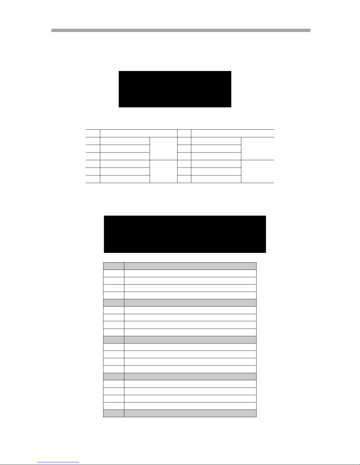
2.2 REAR PANEL LAY OUT
VT-ST1640H
VT-ST840H
VT-ST480H
1. POWER SWITCH
This switch turns the DVR on or off.
2. GROUND
Ground connector.
3. POWER IN
DC power socket for 12VDC 6.67 Amps.
Page 22

SAGA “ST-H” Series
21
4. ALARM INPUT
Alarm input 1 through 16 on VT-ST1640H, 1 through 8 on VT-ST840H and 1
through 4 on VT-ST440H.
5. RS-485 TERMINAL BLOCK
Terminal blocks for RS-485.
6. TIME SYNCHRONIZATION
Input and Output terminal blocks for time synchronization between DVRs.
7. RELAY OUT
Terminal blocks for relay out 1 through 4.
8. SERIAL(RS-232C)
Reserved; the RS-232C port can be used to connect a variety of devices to
control the DVR.
9. VGA OUTPUT
D-sub 15-pin connector for PC monitor out.
10. USB REAR 1 / USB REAR 2
The USB 2.0 ports can be used to connect to numerous USB 2.0 backup
devices including VT-XHD10U external HDD add-on bays, external optical drives
and USB memory sticks.
11. RJ-45 ETHERNET PORT
10/100Base-T RJ-45 port for network connection.
12. AUDIO OUTPUT
RCA, connectors used for audio signal output.
13. S-VIDEO OUTPUT
S-video, connector used for main monitor video signal output.
14. SPOT OUTPUT
Spot monitor BNC connector for composite video signal output.
15. MAIN MONITOR OUTPUT
BNC, connector used for main monitor composite video signal output.
16. AUDIO INPUT
RCA connectors for audio signal input.
17. CAMERA INPUT
BNC connectors for composite video signal input.
18. CAMERA LOOP OUTPUT
Self-terminating BNC, connectors used for composite video signal loop output.
Page 23
SAGA “ST-H” Series
22
2.3 Remote Control
Button Name Description
1 REMOTE
CONTROLLER ID
REMOTE CONTROLLER ID in the system
setup
2 (IRIS-/+)
Iris close and open of PTZ /
Frame by Frame(field by field) playback
3 (ZOOM-/+) Zoom in and out of PTZ
4 SPOT / ESC
Enter the spot mode / Return to the previous
mode
5 ENTER (HOME) Enter / Go home in PTZ mode
6 ( ) / ALARM
RESET
Move the cursor in left direction in the
setup menu. / Release the event signal
7 ( ) / MENU
Move the cursor up to the next line in the
setup menu / Display the setup menu
8 ( ) / PIP
Move the cursor down to the next line /
Enter the PIP mode
9 ( ) / D-ZOOM
Move the cursor in right direction in the
setup menu. / Control of zoom in and out
10 AUTO / ( - ) / F(-)
Auto sequence / Downward value /
Focus control of PTZ
11 FREEZE / ( + ) / F(+)
Freeze / Up-going value /
Focus control of PTZ
12 SEARCH / (PRESET)
Display the search menu /
Enter the preset mode of PTZ
13 COPY / (AF) Display the copy menu / Auto focus of PTZ
14 BOOKMARK / (PTZ)
BOOKMARK SEARCH /
Enter the PTZ mode
15 SLOW ( )
Press this button to slow-down playback
speed
16 PLAY / PAUSE ( )
Press this button to begin playback. If press
again during the playback, a still picture is
displayed
17 FAST ( )
Press this button to speed-up playback speed
18 LV/PB ( )
Convert the screen into real display mode
during the playback
19 DIR ( )
Change the direction of playback
20 RECORD ( )
Begin and stop recording
21 MULTI Display multi-screen
22 TEXT Reserved
23 AUDIO SELECT Audio select button
24 CHANNEL ID Camera number select button
25 FUNCTION
Controls “USER” mode of RELAY 4
SELECT
1
4
3
8
10
11
14
13
19
1
22
23
2
5
6
9
12
15
1
1
20
2
2
24
7
Page 24

SAGA “ST-H” Series
23
2.4 Mouse Control
1 LEFT MOUSE BUTTON a) Double-click in the main window: Full
screen display./ Return the multi-screen.
b) Double-click in the menu
screen: Select item or icon.
2 SCROLL WHEEL
Scroll up or down to change the value of
the selected item.
3 RIGHT MOUSE BUTTON a) Single-click in the main window: Enter
main menu.
b) Double-click in the menu screen: Exit
to main screen.
1
2
3
Page 25

SAGA “ST-H” Series
24
III. INSTALLATION AND CONNECTIONS
3.1 CONNECTIONS LAYOUT
Page 26

SAGA “ST-H” Series
25
3.2 VT-XHD10U
Page 27

SAGA “ST-H” Series
26
3.3 EXTERNAL TERMINAL CONNECTION
3.3.1 RS-485
3.3.2 TIME ADJUST
No
DES CRI PTI ON
1 TA(TX+) RS485:Transmit data
2 TB(TX-) RS485: Receive data
3 GND
NO
DES CRI PTI ON
FAL LIN G E DGE
1 TIME REFERENCE INPUT TTL
2 TIME REFERENCE OUTPUT
To Other Time Adjust
Page 28
SAGA “ST-H” Series
27
3.3.3 RELAY OUTPUT
3.3.4 ALARM SENSOR INPUT
NO
DES CRI PTI ON
NO
DES CRI PTI ON
1 NO(Normal Open) 7 NO(Normal Open)
2 CM(Common) 8 CM(Common)
3 NC(Normal Close)
ALARM
9 NC(Normal Close)
MD
4 NO(Normal Open) 10 NO(Normal Open)
5 CM(Common) 11 CM(Common)
6 NC(Normal Close)
V-LOSS
12 NC(Normal Close)
POWER
USER
NOT USED
HDD ERROR
No DESCRIPTION
1 EXTERNAL ALARM 1 INPUT
2 EXTERNAL ALARM 2 INPUT
3 EXTERNAL ALARM 3 INPUT
4 EXTERNAL ALARM 4 INPUT
G ALARM IN COMMON GND
5 EXTERNAL ALARM 5 INPUT
6 EXTERNAL ALARM 6 INPUT
7 EXTERNAL ALARM 7 INPUT
8 EXTERNAL ALARM 8 INPUT
G ALARM IN COMMON GND
9 EXTERNAL ALARM 9 INPUT
10 EXTERNAL ALARM 10 INPUT
11 EXTERNAL ALARM 11 INPUT
12 EXTERNAL ALARM 12 INPUT
G ALARM IN COMMON GND
13 EXTERNAL ALARM 13 INPUT
14 EXTERNAL ALARM 14 INPUT
15 EXTERNAL ALARM 15 INPUT
16 EXTERNAL ALARM 16 INPUT
G ALARM IN COMMON GND
Page 29

SAGA “ST-H” Series
28
3.3.5 VGA PIN LAYOUT
3.3.6 RS-232C PIN LAYOUT
No
DES CRI PTI ON
1 RED(Red Video [75ohm, 0.7Vp-p] )
2 GREEN(Green Video [75ohm, 0.7Vp-p] )
3 BLUE(Blue Video [75ohm, 0.7Vp-p] )
4~12 Reserved
13 HSYNC or CSYNC (Horizontal or Composite Sync.)
14 VSYNC (Vertical Sync.)
15 Reserved
No Des cri pti on
No Des cri pti on
1 DCD Data Carrier Detect 6 DSR Data Set Ready
2 RxD Receive data 7 RTS RS232C: RX/TX data
3 TxD Transmit data 8 CTS RS232C: RX/TX data
4 DTR Data Terminal Ready 9 RI Ring Indicator
5 GND Signal Ground
Page 30
SAGA “ST-H” Series
29
IV. BASIC OPERATION
This section will cover basic features of the DVR, including its main screen and the
explanation of some of the alerts. It will also cover the DVR status, the view
modes of the DVR, automatic sequence, digital zoom, basic playback modes and
audio playback.
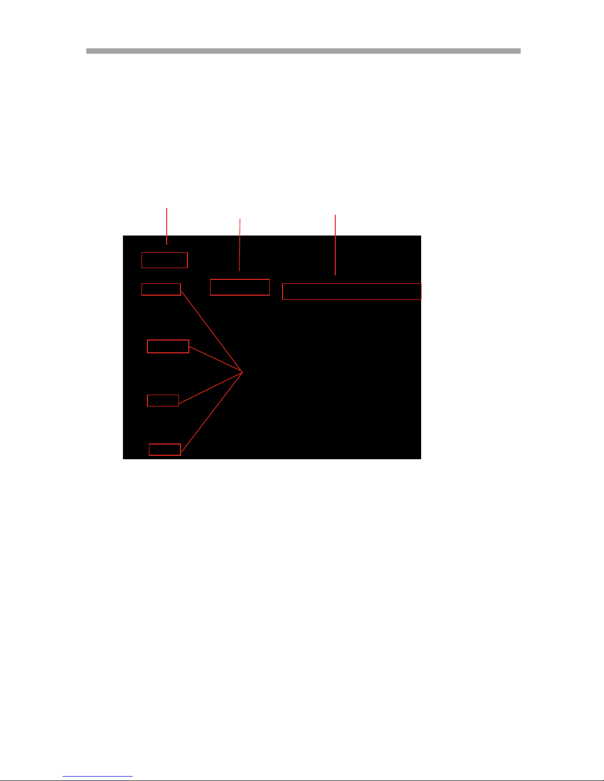
4.1 MAIN SCREEN
1. REMAINING HARD DRIVE SPACE / PLAYBACK STATUS
The remaining hard drive space is displayed either in percentage or in Gigabytes. If
the hard drive overwrite is set to on, the counter will remain as 0 and the DVR
will continue to write on to the hard drive from the beginning. The counter will
remain 0 as long as the hard drive is full with previously recorded data, and will
display its original size once the hard drive is formatted. In playback mode, it
displays the direction and the speed of the playback.
2. CHANNEL STATUS
The status of each channel is displayed in color codes.
White: non-recording
Yellow: continuous (manual) recording
Red: event recording
Green: schedule recording
1
2
3
4
Page 31

SAGA “ST-H” Series
30
3. DATE AND TIME
Current date and time is displayed when in live monitoring mode. Recorded
date and time is displayed when in playback mode.
4. CHANNEL INFORMATION
The channel information is displayed. When the channel is in normal recording
mode, it will display the channel title as entered by the user. When the channel
is in event recording mode, it will display the appropriate event recording mode:
alarm, motion and video loss.
4.2 STATUS SCREEN
Press the Status button on the front panel of the DVR using the Enter button to see the
below Screen
Move the Cursor to the DVR STATUS icon using on the remote & press the
Enter button to get the below Screen.
Page 32

SAGA “ST-H” Series
31
The status screen displays the basic information about the DVR. Press the STATUS
button to access the information screen.
1. FIXED HDD TOTAL SPACE
Displays the total amount of installed hard drive space. Including the hard drive
space in the expansion bays.
2. FIXED HDD FREE SPACE
Displays the available remaining hard drive space. Including the hard drive
space in the expansion bays.
3. BACKUP HDD TOTAL SPACE
Displays the total amount of backup hard drive space. Including the hard drive
space in the expansion bays. Backup hard drive total space will display zero
bytes if none of the hard drives is designated as backup hard drives.
4. BACKUP HDD FREE SPACE
Displays the available remaining backup hard drive space. Including the hard
drive space in the expansion bays. Backup hard drive total space will display
zero bytes if none of the hard drives is designated as backup hard drives.
5. RECORD PROGRAM
Displays current recording program.
6. USB STORAGE
Displays the size of the external hard drive space or USB Flash Memory.
7. USB CD / DVD
Displays the status of installed CD or DVD optical drive.
8. SOFTWARE VERSION
Page 33

SAGA “ST-H” Series
32
Displays the current software version of the DVR.
9. HARDWARE VERSION
Displays the current hardware version of the DVR.
4.3 NETWORK STATUS
Move the cursor to the Network Status using button from the remote & then click on it
using the Enter button to get the below screen.
1. DHCP (DYNAMIC HOST CONFIGURATION PROTOCOL)
Displays the status of the DHCP application.
2. IP ADDRESS
Displays currently assigned IP address.
3. SUBNET MASK
Displays currently assigned subnet mask.
4. GATEWAY
Displays currently assigned gateway.
5. DNS (DOMAIN NAME SERVER)
Displays currently assigned DNS server information.
Page 34

SAGA “ST-H” Series
33
6. PORT
Displays currently assigned network port.
7. DYNAMIC IP SERVER
Displays currently assigned backup IP server.
8. BACKUP IP SERVER
Displays the IP of the Back up Server.
9. MAC ADDRESS
Displays the DVR’s MAC address (Media Access Control address).
10. IP SERVER RESPONSE
Indicates the connectivity status with the IP server.
4.4 RECORDING BITRATE
Move the cursor to the RECORDING STATUS icon and press the ENTER button to see the
below Screen. The screen below gives information about the recording bits on all the 16
channels.
Page 35

SAGA “ST-H” Series
34
4.5 LIVE VIEW
The live view displays each channel at 30 images per second, for the total of 480
images per second for VT-ST1640H, 240 images per second for VT-ST840H and
120 images per second for VT-ST440H.
4.5.1 LIVE VIEW MODE SEQUENCE
Press the DISPLAY button to toggle between different views modes.
4.5.1.1 VT-ST1640H
16 Channel Mode 13 Channel Mode 10 Channel Mode
9 Channel Mode A 9 Channel Mode B 7 Channel
6 Channel Mode 4 Channel Mode A 4 Channel Mode B
4 Channel Mode C 4 Channel Mode D 4 Channel Mode E
Page 36

SAGA “ST-H” Series
35
4.5.1.2 VT-ST840H
8 Channel Mode 7 Channel Mode 6 Channel Mode
4 Channel Mode A 4 Channel Mode B 4 Channel Mode C
4 Channel Mode D 4 Channel Mode E
4.5.2 FULL SCREEN DISPLAY
Press the desired channel button to directly display the channel on the monitor.
Press (+10) then a secondary number for any channels higher than 9.
Press Numeric button to display Channel 1.
Page 37

SAGA “ST-H” Series
36
Press the +10 button and then number 2 to display Channel 12.
4.5.3 AUTOMATIC SEQUENCE
Press the SEQ button to activate the automatic sequence display. Please change
“ADD AUTO SINGLE” option to ON to include single channel display into the
automatic sequence. Any of the view modes can be skipped by selecting the dwell
time to 0.
16 Channel Mode 10 Channel Mode 7 Channel Mode
4 Channel Mode 1 Channel Mode
Page 38

SAGA “ST-H” Series
37
4.6 FREEZE
The freeze function allows the user to freeze the live view mode at any given time.
There are two modes in which the freeze function is effective: single screen (full
screen) mode and multi-screen mode.
4.6.1 SINGLE SCREEN LIVE MODE
In the screen View Mode, Press the FREEZE button to
Freeze the live Screen.
As the screen freezes, “FREEZE” will be
displayed in the upper left corner of the screen.
Press the FREEZE button once more to unfreeze
the screen.
Page 39

SAGA “ST-H” Series
38
4.7 ZOOM
During the live view mode, it is possible to zoom into a section of the screen to
get a digital close-up of up to 2 times the normal size.
NOTE: VT-ST1640H/ST840H/ST440H cannot support the zoom function during
the playback.
Press the numeric button to select the channel to
zoom into.
Press the ZOOM button to enter the zoom mode.
The initial zoom ratio is 2X the normal size.
Use the directional buttons to move the zoom
window to the desired location.
Press the ESC button to exit out of the zoom
mode.
Page 40

SAGA “ST-H” Series
39
4.8 PICTURE-IN-PICTURE (PIP)
Select the background channel by pressing the
desired numeric button.
Press the PIP button to activate the PIP mode.
Pressing the numeric buttons will change the
PIP window to change the channel to the
desired channel.
Use the directional buttons to place the PIP
window to the desired location on the screen.
Press the ESC button to exit from the PIP
mode.
Page 41

SAGA “ST-H” Series
40
4.9 SPOT MONITOR
The spot monitor allows viewing of individual cameras in live mode while the main
monitor may be busy with different tasks, such as playback. The ST series offers a
single channel spot output.
During any view modes, press the SPOT button
for Spot Monitor Mode.
Press any channel numbers to display the channel
in full screen mode on the spot monitor.
The spot monitor will display the channel
accordingly.
Press the SPOT button to exit from Spot Monitor
Mode.
4.10 BASIC RECORDING
When the REC button is pressed, the DVR uses Program 6, which is the default
record setting:
There are total of 10 customizable record programs Please note that QUICK SETUP
supersedes any other recording settings when activated.
The factory default record programs are as follows:
Page 42

SAGA “ST-H” Series
41
RECORD
PROGRAM
0
1 2 3 4 5 6 7 8 9
EVENT
TYPE
COMPLE
X
SINGLE SINGLE
COMPLE
X
SINGLE
SINGLE
COMPLE
X
SINGLE SINGLE
COMPLE
X
EVENT
OPTION
CH
ONLY
CH
ONLY
CH
ONLY
CH
ONLY
CH
ONLY
CH
ONLY
CH
ONLY
CH
ONLY
CH
ONLY
CH
ONLY
IMAGE
SIZE
720X240
360X240 360X240 360X240
720X24
0
720X24
0
720X240
720X48
0
720X48
0
720X480
NORMAL
RECORD
0
8 4 15 4 2 8 2 0 4
EVENT
SINGLE
-
15 8 4 4
EVENT
COMPLEX
0
- - - - - - 5 or 3
NORMAL
QUALITY
NORMAL
LOW NORMAL FINE BEST LOW NORMAL FINE BEST LOW
EVENT
QUALITY
NORMAL
LOW NORMAL FINE BEST LOW NORMAL FINE BEST LOW
PREALARM
5
5 5 5 5 5 5 5 5 5
POSTALARM
10
10 10 10 10 10 10 10 10 10
EVENT A/L/M A/L/M A/L/M A/L/M A/L/M A/L/M A/L/M A/L/M A/L/M A/L/M
10 PREDEFINED PROGRAMS ARE INCLUDED BY DEFAULT.
PROGRAMS ARE AVAILABLE FROM 0 to 9.
FEATURES
RECORDING MODES:
NORMAL (Continuous): 4
ips.
EVENT: 4 ips.
RESOLUTION : 720 X
480
QUALITY: N/N.
PRE/POST: 5/10.
EVENT TYPE: A/L/M.
Page 43

SAGA “ST-H” Series
42
PROGRAM 1
FEATURES
RECORDING MODES:
NORMAL (Continuous): 8 ips.
EVENT: 0 ips.
RESOLUTION: 360 X 240
QUALITY: L/L.
PRE/POST: 5/10.
EVENT TYPE: A/L/M.
PROGRAM 2
FEATURES
RECORDING MODES:
NORMAL (Continuous): 4 ips.
EVENT: 0 ips.
RESOLUTION: 360 X 240
QUALITY: N/N.
Page 44

SAGA “ST-H” Series
43
PRE/POST: 5/10.
EVENT TYPE: A/L/M.
PROGRAM 3
FEATURES
RECORDING MODES:
NORMAL (Continuous): 15 ips.
EVENT: 15 ips.
RESOLUTION: 360 X 240
QUALITY: F/F.
PRE/POST: 5/10.
EVENT TYPE: A/L/M.
PROGRAM 4
Page 45

SAGA “ST-H” Series
44
FEATURES
RECORDING MODES:
NORMAL (Continuous): 4 ips.
EVENT: 0 ips.
RESOLUTION: 720 X480
QUALITY: B/B.
PRE/POST: 5/10.
EVENT TYPE: A/L/M.
PROGRAM 5
FEATURES
RECORDING MODES:
NORMAL (Continuous): 2 ips.
EVENT: 0 ips.
RESOLUTION: 720 X480
QUALITY: L/L.
PRE/POST: 5/10.
EVENT TYPE: A/L/M.
PROGRAM 6
Page 46

SAGA “ST-H” Series
45
FEATURES
RECORDING MODES:
NORMAL (Continuous): 8 ips.
EVENT: 8 ips.
RESOLUTION: 360 X 240
QUALITY: N/N.
PRE/POST: 5/10.
EVENT TYPE: A/L/M.
PROGRAM 7
FEATURES
RECORDING MODES:
NORMAL (Continuous): 2 ips.
EVENT: 0 ips.
RESOLUTION : 720 X 480
QUALITY: F/F.
PRE/POST: 5/10.
EVENT TYPE: A/L/M.
PROGRAM 8
Page 47

SAGA “ST-H” Series
46
FEATURES
RECORDING MODES:
NORMAL (Continuous): 0 ips.
EVENT: 4 ips.
RESOLUTION : 720 X 480
QUALITY: B/B.
PRE/POST: 5/10.
EVENT TYPE: A/L/M.
PROGRAM 9
FEATURES
RECORDING MODES:
NORMAL (Continuous): 4
ips.
EVENT: 4 ips.
RESOLUTION : 720 X
480
QUALITY: L/L.
PRE/POST: 5/10.
EVENT TYPE: A/L/M.
Page 48

SAGA “ST-H” Series
47
Press the REC button to start recording. The
Circles representing the channel status will
change color based on the recording mode. Press
the REC button once again to stop the recording.
4.11 BASIC PLAYBACK
4.11.1 PLAY / REVERSE PLAY / PAUSE / STOP
Press the PLAY / PAUSE button and the play
icon will be displayed. The DVR starts the
playback from the earliest recorded data if the
playback mode is entered for the first time
Press the DIRECTION button to change the
playback direction
Press the PLAY / PAUSE button during the
playback to pause the playback.
Press the LIVE button to exit to the live view
mode.
Page 49

SAGA “ST-H” Series
48
4.11.2 FAST FORWARD / REWIND
During the playback or when the playback is paused, the video can be fast
forwarded or rewound in two different methods.
4.11.2.1 JOG SHUTTLE
Turn the shuttle ring clockwise to fast forward to
the desired location. Each increment on the shuttle
ring represents the speed of fast forward on the
screen. Starting with 2X speed, each additional
increment represents twice the previous speed. The
maximum fast forward speed is 128X the normal speed. Releasing the shuttle ring
will bring the fast forward to a pause.
Turn the shuttle ring counter-clockwise to rewind to
the desired location. The same speed increment and
icon concept is applied for the rewind. Releasing
the shuttle ring will bring the rewind to a pause.
4.11.2.2 FAST / DIRECTION button
The FAST button accelerates the speed of playback in
one direction. Each pressing of the button accelerates
the speed twice the previous speed. In other words,
from normal speed, the acceleration increment is 2X,
4X, 8X, 16X, 32X, 64X and 128X.
Page 50

SAGA “ST-H” Series
49
Pressing the DIRECTION button will change the
direction of fast forward to rewind while maintaining
the same speed.
4.11.3 PICTURE BY PICTURE
Press the PLAY / PAUSE button to pause the
video playback,
Turn the jog dial clockwise to review and to
advance through the recorded data picture-bypicture. If the jog dial is stopped, the playback
will return to paused playback mode.
Turn the jog dial counter-clockwise to play in
reverse and view recorded data picture-by-picture.
If the jog dial is stopped, the playback will return
to paused playback mode.
Page 51

SAGA “ST-H” Series
50
4.11.4 SLOW
The SLOW button slows down the speed of
playback in one direction. Each time you press
the button it will further slow down the speed
twice the previous speed. In other words, from
normal speed, the slow down increment is 1/2X,
1/4X, 1/8X, 1/16X, 1/32X, 1/64X and 1/128X.
Pressing the DIRECTION button will change the
direction of slow playback to the opposite
direction while maintaining the same speed.
4.11.5 LOOP PLAYBACK
The playback can be marked in two different locations so that it can be looped
repeatedly.
During any playback mode, press the A button to
mark the beginning of the loop, POSITION A.
When the desired location is found, press the B
button to mark the end of the loop, POSITION B.
The desired location can be reached by any
playback functions such as fast forward, slow, and
etc.
Page 52

SAGA “ST-H” Series
51
As soon as the end of the loop is marked, then
the playback returns to POSITION A.
When the end the loop is reached, the playback
returns to POSITION A and the loop playback is
repeated.
Press the CLEAR button to exit from the loop
playback mode.
4.11.6 BOOKMARK
The bookmark provides a quick and easy way to mark the desired location during
playback so that it can be easily retrieved for later playback.
During the playback, pause by pressing the
PLAY / PAUSE button when the desired
location has been reached.
Press the BOOKMARK button to mark the
current location.
Page 53

SAGA “ST-H” Series
52
4.11.7 AUDIO PLAYBACK
The audio is always recorded in real time regardless of the recording speed. To
listen to the desired audio channel, press the AUDIO SEL button and then channel
button.
By default, the audio will playback along with the equivalent video camera (i.e.
channel 1 audio will play back along with channel 1 video).
Page 54

SAGA “ST-H” Series
53
V. ADVANCED OPERATION
This section will cover advanced features of the DVR such as backup (copy), pan
tilt and zoom camera controls, alarm, video loss and motion recording, and various
playback search options.
5.1 BACKUP
The DVR is capable of backing up to various media, such as DVD-RW, DVDRAM, CD-R CD-RW, USB Flash drives. Please note that besides the optical media,
the backup devices must be USB 2.0 compliant and they can be connected to any
of the three available USB slots. Every time a backup is made, the mini player
will be copied along with the content to facilitate viewing of the backup video on
any Windows based personal computers. All backup media will include a multichannel small viewer.
5.1.1 CD-RW / DVD-RW / DVD+RW / DVD RAM
The DVR is equipped with a DVD multi / CD-RW drive for backups. RW media
was specifically chosen because of its unique ability to be used over and over.
Data backups can be written to the same RW disk until its maximum capacity is
reached. Once the capacity is reached, the disk can then be reformatted and reused
over and over.
Press the COPY button to enter the copy Screen.
CD-RW, DVD-RW and DVD-RAM media must be formatted prior to backup. Select
MEDIA FORMAT and then press the ENTER button to access Media Format
submenu.
Page 55

SAGA “ST-H” Series
54
Select the INTERNAL CD/DVD-RW or USB_REAR1or USB-REAR2 or
USB_FRONT by
Pressing (-) or (+) button.
Highlight the MEDIA FORMAT and Press the ENTER button to begin formatting.
FORMATTING will be displayed during the process. The process may take up to
approximately 20 minutes depending on the format of the backup disk. When the
process is completed, SUCCESS will be displayed.
Press ESC button to go back to the previous menu.
Highlight COPY and press the ENTER button to access the COPY Submenu as
shown in the above screen.
Page 56

SAGA “ST-H” Series
55
Select the location of the file to be backed up from.
If the location is unknown, leave the HDD ID on NORMAL
Select the channels to be backed up. By default, all channels are selected. To
exclude a channel, highlight a channel number and then switch them to: “--“.
The start and the end times of the available files are listed automatically as shown
above.
Select the start time and the end time of the period to be backed up, and then
press the ENTER button to start the backup.
When prompted, enter an eight digit numeric password to encrypt the backup. This
password will be needed to later retrieve the data. Data encryption can be bypassed
by pressing the ESC button.
The DVR will start creating a buffer for the
selected data to be backed up. The status of the
buffer being created will be displayed in the
upper right corner of the screen.
The backup progress is displayed on the right
upper corner of the screen, and will disappear
automatically when the backup process is finished.
Page 57

SAGA “ST-H” Series
56
5.2 COPY STATUS
During any backup process, a detailed description of the copy process can be
viewed. Copy status will display the start and end of the data to be backed up,
and the current time of the data being copied.
Highlight COPY STATUS and then press the ENTER button to see the copy status.
Below Screen displays the Current Copy Status.
Page 58

SAGA “ST-H” Series
57
5.3 Recommended Brands
Below are the recommended brands for USB Stick, CD-R, CD-RW, and DVD -R W & DVD-RAM.
USB MEMORY STICK
SONY SANDISK with and without U3 software
SAMSUNG HP Kingston
TOSHIBA LG PNY
Memorex
CD-R,CD-RW,DVD-RW & DVD-RAM
IMATION ATIVA
PANASONIC MEMOREX
NOTE: It is strictly recommended to use the USB Stick which has only the storage function.
DO NOT USE any USB stick which comes with built-in Drivers & A pplications.
<Figure 1: NON Standard USB A-Type > <Figure2: Standard USB A-Type >
NOTE:
It’s preferable to use the USB device mentioned in Figure 2 rather than Figure 1.
Please make sure that the DVR is turned OFF before inserting the USB device into the USB port while
using the USB device mentioned in Fig 1.
When a User uses the USB Stick mentioned in the Figure 2, there is no need to follow the above step.
The user has to format the plug –in device like USB Memory Stick or CD-RW/ DVD-RW before copying.
Also note that when the user wants to copy using the CD-RW or DVD-RW ,
He has to plug in the power of the DVD-RW or CD-RW initially.
Page 59

SAGA “ST-H” Series
58
5.4 PAN / TILT / ZOOM CAMERA CONTROL
The DVR comes with an extensive list of compatible PTZ cameras. Please read
and follow the PTZ manufacturer’s instruction manual and understand its settings
fully prior to proceeding to attempt to connect and control the PTZ camera through
the DVR.
5.4.1 BASIC PAN / TILT / ZOOM CONTROL
Select the desired channel by pressing the numeric
button for the full screen view.
Press the PTZ button to enter the PTZ camera
control mode. Use the directional buttons for
the pan and tilt movement, +/- buttons to focus
in/out, or AF button for auto focus, and the
shuttle ring to zoom in and out.
The movement speed of the PTZ camera can be changed by pressing the
FUNCTION button and then the + or – button to increase or decrease the speed.
5.4.2 CREATING AND MOVING TO PRESET POINTS
During the PTZ control mode, press the
PRESET button to activate the PTZ (PRESET)
MOVE mode. If there are any preset points
predefined, pressing a numeric button will move
the PTZ camera to the preset points. A total
of 16 preset points can be recalled.
Page 60

SAGA “ST-H” Series
59
If there are no preset points predefined, then
press the PRESET button once again to activate
PTZ (PRESET) SET mode. Move the PTZ
camera to the desired location, then press the
numeric buttons to define the numbers to the
locations. A total of 16 preset points can be
defined.
VI. ADVANCED RECORDING
Advanced recording is comprised of customizing various event recording options
such as alarm, video loss and motion. Event recording maximizes recording time
with the available storage space. Event recording can also utilize the backup mode
hard drives in addition to normal recording hard drives for duplicate copies of the
events.
Prior to activating event recording, please verify that event options are activated in
either the QUICK SETUP menu or the RECORD PROGRAM menu. Please note
that if QUICK SETUP is not used, then certain parameters in the EVENT menu
must be activated for the event recording to work properly. Moreover, please verify
that the proper program number is being used under RECORD SETUP.
There are two methods for event recording. The first method is recording events in
addition to manual recording, and the second method is event recording only. The
first method involves leaving the REC button on to start recording manually and
combining event recording. This would be useful in a scenario where a location
needs to be recorded continuously even at a very minimal recording speed, but
when an event is triggered, the recording speed is boosted to the desired pictures
per second. The second method involves leaving the REC button off so that only
events are recorded.
The following settings will assume that the second method is used for event
recording. With either method, the events will trigger the designated relays and
send out notification e-mails if the e-mail addresses have been defined.
6.1 ALARM RECORDING
Alarm recording is a form of event recording that triggers off of the circuit lines
connected to the terminal blocks in the rear of the DVR. Typical circuits comprise
of normally closed circuits (NC) and normally open circuits (NO).
Verify that the alarm option has been selected in either QUICK SETUP or
RECORD PROGRAM.
Page 61

SAGA “ST-H” Series
60
The channels on which the alarm is triggered will
display the “ALARM” message. The REC button
will light up as the DVR starts to record and the
channel status will change to red.
The recording will include the pre and post
recording time on the channels that are recording.
Below are the steps to perform Alarm Recording.
STEP 1
QUICK MENU
QUICK SETUP MANUAL
EVENT ALARM
STEP 2
EVENT MENU
EVENT SCREEN MODE SCREEN HOLD
EVENT CHECK ON
EVENT MESSAGE ON
STEP 3
SENSOR INPUT:
Select the right sensor type according to the installed Sensor type in the unit.
NORMAL OPEN: Sensor is open in normal times.
NORMAL CLOSE: Sensor is close in normal times.
NOT INSTALLED: No Sensors are connected to the DVR unit.
6.2 VIDEO LOSS RECORDING
Video loss recording is a form of event recording that is triggered when a channel
loses its video input signal. Video loss recording is useful to have other channels
compensate for the loss of the video signal on a specific channel. For example,
when a video loss occurs on channel 1, then the DVR can start recording on
channel 2, 3 and 4.
Moreover, the channel which loses the video signal will retain the last five seconds
of the video to retain what occurred before the video loss.
Verify that the video loss option has been selected in either QUICK SETUP or
RECORD PROGRAM.
Page 62

SAGA “ST-H” Series
61
The channel on which the video loss occurred
will display the “VLOSS” message. The REC
button will light up as the channels that are
designated to record when a specific channel has
a video loss start recording.
On the example to the left, channels 2, 3 and 4
are designated to record when channel 1 goes out.
The recording will include the pre and post recording time on the channels that are
recording.
Below are the steps to perform Video Loss Recording.
STEP 1
QUICK MENU
QUICK SETUP MANUAL
EVENT V-LOSS
STEP 2
EVENT MENU
EVENT SCREEN MODE SCREEN HOLD
EVENT CHECK ON
EVENT MESSAGE ON
6.3 MOTION RECORDING
Motion recording is yet another effective form of event recording that is triggered
when a channel detects motion in its field of view as the MPEG compression
algorithm allows for accurate and error-free motion detection.
The channels which detect motion will display the
“MOTION” message. The REC button will light
up and the channel status will change the color to
red in the channels in which the motion was
detected.
The recording will include the pre and post
recording time on the channels that are recording.
Below are the steps to perform Motion Recording.
Page 63

SAGA “ST-H” Series
62
STEP 1
QUICK MENU
QUICK SETUP OFF
EVENT ALL
STEP 2
EVENT MENU
EVENT SCREEN MODE SCREEN HOLD
EVENT CHECK ON
EVENT MESSAGE ON
VII. MAIN MENU
Before operating the DVR, please make sure that you have properly connected all the cables and
HDD’s.
By Pressing the Menu button on the DVR or from the Remote, the screen below will pop-up.
Page 64

SAGA “ST-H” Series
63
7.1 QUICK SETUP
By pressing the Quick setup button, the screen below will pop–up.
Select the desired item by pressing button from the remote controller.
7.1.1 QUICK SETUP
Select “ON” or OFF by pressing the button or (+) and (-) button from the remote or
Front Panel.
7.1.2 IMAGE SIZE
Select the desired IMAGE SIZE for recording as shown below by pressing the button
from the remote.
a) 360 X 240.
b) 720 X 240.
c) 720 X 480.
7.1.3 RECORD FRAME
User can select the desired frame rate for normal recording using the button or (+) and
(-) button from the remote or Front Panel.
NOTE: If you select “ON”, RECORD MENU will be disregarded.
Page 65

SAGA “ST-H” Series
64
7.1.4 IMAGE QUALITY
Select the desired image quality using the button or (+) and (-) button from the remote
or Front Panel.
There are 4 different types of image quality like Best, Fine, Normal and Low.
7.1.5 EVENT
You can select any type of EVENT by using the button or (+) and (-) button from the
remote or Front Panel. The User can select all of the events, by choosing “ALL”. Select
“OFF” to stop recording an event.
The default Value is “ALL”.
7.1.6 PRE RECORD TIME
Select the desired time for pre-recording using the button or (+) and (-) from the
remote or Front Panel.
When video loss, alarm or motion is detected, the DVR will store pre-recorded data during
the selected time.
The pre-recording time can be set from 0 second to 5 second and the default is “5”.
7.1.7 POST RECORD TIME
Select the desired time for post-recording using the button or (+) and (-) from the
remote or Front Panel.
When video loss, alarm or motion is detected, the DVR will store post-recorded data during
the selected period.
The post-recording time can be set from 0 second to 60 second and the default is “10”.
7.1.8 PREVIEW QUALITY
Move the Cursor to the PREVIEW QUALITY & press the Enter button to see the below
Screen.
NOTE: The pre- and post- recording is not valid in normal recording mode.
Page 66

SAGA “ST-H” Series
65
Select the desired recoded quality using the button or (+) and (-) from the remote or
Front Panel.
User can have a preview of the recorded Video in 4 different levels like Best, Fine, Normal
and Low.
7.1.9 AUDIO RECORD
Select “ON” or “OFF” using the button or (+) and (-) from the remote or Front Panel
to record audio.
7.1.10 REMOTE CONTROL ID
Select the arbitrary remote controller ID using the button or (+) and (-) from the remote
or Front Panel.
7.1.11 SAVE
User can save the changes done in the QUICK Menu by clicking the SAVE button.
7.2 SCREEN
You can select SCREEN Menu by pressing the Enter button from the remote.
By pressing the SCREEN button with the help of the Enter button on the remote, the below screen
will appear.
Page 67

SAGA “ST-H” Series
66
Select the desired item by pressing button from the remote controller.
7.2.1 AUTO SEQUENCE
At the SCREEN menu,
Move the cursor to the AUTO SEQUENCE using buttons.
Press the ENTER button when the cursor is on the AUTO SEQUENCE the following
screen
Will appear. (It’s different from model to model)
Move the cursor to each single or split channel using the , buttons.
When the desired channel is selected, change the value of AUTO SEQUENCE duration
using the button or (+) and (-) from the remote or Front Panel to set the length of
time for switching each channel in sequence.
* The value is from 1SEC to 60SEC but the default is “3SEC”.
To exit this AUTO SEQUENCE menu, press the ESC button.
Page 68

SAGA “ST-H” Series
67
VIDEO LOSS SKIP : If selected ON, every VIDEO LOSS channel will be skipped in
the AUTO SEQUENCE mode. The default is “ON”.
ADD AUTO SINGLE: If selected OFF, every single channel will be skipped in
the AUTO SEQUENCE mode.
The default is “OFF”.
7.2.2 DISPLAY
At the SCREEN menu,
Move the cursor to the DISPLAY using buttons.
Press the ENTER button when the cursor is on the DISPLAY the following screen will
appear.
To exit this DISPLAY menu, press the ESC button.
7.2.2.1 HDD FREE SPACE
At the DISPLAY menu,
Move the cursor using the buttons to select the HDD FREE SPACE.
Press button or (+) and (-) from the remote or Front Panel to choose “ON” or “OFF”.
* The default is “ON”.
Page 69

SAGA “ST-H” Series
68
7.2.2.2 HDD FREE SPACE MODE
At the DISPLAY menu,
Move the cursor using the buttons to select the HDD FREE SPACE MODE.
Use the button or (+) and (-) from the remote or Front Panel to choose “PERCENT”
or “GIGABYTE”.
* The default is “PERCENT”.
7.2.2.3
RECORD STATUS
At the DISPLAY menu,
Move the cursor using the buttons to select the RECORD STATUS.
Use the button or (+) and (-) from the remote or Front Panel to choose “ON” or
“OFF”.
* The default is “ON”.
7.2.2.4 CLOCK DISPLAY
At the DISPLAY menu,
Move the cursor using the buttons to select the CLOCK DISPLAY.
Use the buttons or (+) and (-) from the remote or Front Panel to choose “ON” or
“OFF”.
* The default is “ON”.
7.2.2.5 DATE & TIME MODE
At the DISPLAY menu,
Move the cursor using the buttons to select the DATE&TIME MODE.
Use the button or (+) and (-) from the remote or Front Panel to choose “YY/MM/DD”
or “MM/DD/YY” or ”DD/MM/YY”.
* The default is “YY/MM/DD”.
ON: Remaining capacity of the fixed (not backup) HDDs will be displayed on the screen.
PERCENT: Remaining capacity of the fixed HDDs will be displayed on the screen in percent.
GIGABYTE: Remaining capacity of the fixed HDDs will be displayed on the screen in gigabyte.
ON: Displaying the recording status of each channel on the screen.
ON: The date and time will be displayed on the screen.
YY/MM/DD: All date and time will be displayed in numbers.
Ex. 2005/01/01 00:00:00
MM/DD/YY: the month section will be displayed in character.
Ex. JAN 01 2005 00:00:00
DD/MM/YY: the day section will be displayed in character.
Ex. 01 JAN 2005 00:00:00
Page 70

SAGA “ST-H” Series
69
7.2.2.6 TITLE DISPLAY
At the DISPLAY menu
Move the cursor using the buttons to select the TITLE DISPLAY.
Use the buttons or (+) and (-) from the remote or Front Panel to choose “ON” or
“OFF”.
* The default is “ON”.
7.2.2.7
TITLE MODE
At the DISPLAY menu,
Move the cursor using the buttons to select the TITLE MODE.
Use the button or (+) and (-) from the remote or Front Panel to choose “TEXT” or
“BITMAP”.
* The default is “TEXT”.
7.2.2.8
BORDER COLOR
At the DISPLAY menu,
Move the cursor using the buttons to select the BORDER COLOR.
Use the button or (+) and (-) from the remote or Front Panel to choose “WHITE” or
“BLACK”.
* The default is “WHITE”.
7.2.2.9 REMOTE CONTROL ID
At the DISPLAY menu,
Move the cursor using the buttons to select the REMOTE CONTROL ID.
Use the button or (+) and (-) from the remote or Front Panel to choose “ON” or
“OFF”.
* The default is “OFF”.
7.2.3 TITLE
At the SCREEN menu,
Move the cursor to the TITLE using buttons.
ON: Each channel title will be displayed on the screen
WHITE: The color of the border line will be displayed on the multi-channel screen in white.
BLACK: The color of the border line will be displayed on the multi-channel screen in black.
ON: The remote controller ID will be displayed on the screen.
A bitmap is a type of graphics file on a computer. You can make characters with bitmap on the setup
window of network client viewer after connecting the computer with DVR.
Page 71

SAGA “ST-H” Series
70
Press the ENTER button when the cursor is on the TITLE and the following screen will
appear.
Use the
buttons to see the next page.
Press the ENTER button after selecting desired channel using the buttons the
following screen will
appear.
Select the character using the
buttons and then press the ENTER
button.
To exit this CHARACTER TABLE screen, press the ESC button.
CHANNEL TITLE MODE: There are “TEXT” and “BITMAP”.
TEXT: Using the CHARACTER TABLE
BITMAP: It is possible to download new characters using the client software if you want.
Page 72

SAGA “ST-H” Series
71
7.2.4 MULTI SCREEN
At the SCREEN menu,
Move the cursor to the MULTI SCREEN using buttons.
Press the ENTER button when the cursor is on the MULTI SCREEN the following screen
will appear.
Several multi-screen viewing modes can be customized using any combination of
cameras. These viewing modes can be disabled and excluded from the view mode
sequence. Customizable multi-screens include: MULTI 4E, MULTI 6, MULTI 7,
MULTI 9B MULTI 10, AND MULTI 13.
7.2.5 COVERT
At the SCREEN menu,
Move the cursor to the COVERT using the buttons.
Press the ENTER button when the cursor is on the COVERT the following screen will
appear.
Page 73

SAGA “ST-H” Series
72
Move the cursor and select the desired item using the buttons.
Use the button or (+) and (-) from the remote or Front Panel to choose “ON” or
“OFF”.
Use the
buttons to see the next page.
7.2.6 SPOT
7.2.6 SPOT
At the SCREEN menu,
Move the cursor to the SPOT using buttons.
Press the ENTER button when the cursor is on the SPOT the following screen will appear.
To exit this SPOT menu, press the ESC button.
7.2.6.1
SPOT MODE
Use the button or (+) and (-) from the remote or Front Panel to select the SPOT
MODE.
MANUAL: Manually select the channel of spot monitor.
EVENT: Event channel will be displayed automatically on spot monitor.
SEQUENCE: Every single channel will be switching and displaying in sequence.
7.2.6.2
SPOT SEQ. TIME
Use the button or (+) and (-) from the remote or Front Panel to set the SPOT SEQ.
TIME.
The duration of spot sequence can be set from 1SEC to 60SEC.
ON: The selected channel will be displayed as black screen (Hidden camera).
SELECT: It is possible to select among “LIVE&PLAYBACK&NETWORK”,
“PLAYBACK&NETWORK”,
“LIVE&NETWORK”, “LIVE&PLAYBACK”, “NETWORK”, “PLAYBACK” and “LIVE”.
- LIVE: To covert selected channels on live screen
- PLAY: To covert selected channels on playback screen
Page 74

SAGA “ST-H” Series
73
7.2.6.3 VIDEO LOSS SKIP
Select “ON” or “OFF” using the button or (+) and (-) from the remote or Front Panel.
If you select “ON”, loss images will be skipped.
7.2.7 CAMERA
At the SCREEN menu,
Move the cursor to the CAMERA using buttons.
Press the ENTER button when the cursor is on the CAMERA the following screen appears.
You can control brightness, contrast, hue and
saturation of each camera.
The default is 50.
7.3 RECORD
Record setup defines various recording options such as record schedule, record programs,
recording time estimate, audio recording, repeat recording, play modes, backup mode, and
holiday recording schedules and recording period setting.
To set up the RECORD menu,
Move the cursor to the RECORD icon using the
in the MENU screen.
Press the ENTER button when the cursor is on the RECORD icon the following screen will
appear.
User can select any item using button from the remote.
Page 75

SAGA “ST-H” Series
74
7.3.1 Record Setup
This menu allows you to configure a weekly recording schedule. In the schedule you must use the
predefined programs (0-9) in order to set up the recording properly. You can use and combine
different predefined programs during the week according with your own needs. (See RECORD
PROGRAM section for more information)
At the RECORD menu,
Press the ENTER button when the cursor is on the RECORD SET U P the follow ing screen will
appear.
Move the cursor to choose the desired time using the buttons.
Select the desired program among PROGRAM 0~9 and POWER OFF using the
buttons or (+) and (-) from the remote or Front Panel.
To enable the programmed time turn the shuttle ring to the right, initially the number will be
green when
enabled it will turn to yellow.
Turn the shuttle ring to the left to release the schedule mode.
Or move the cursor to the desired position and then click the square next to “SCHEDULE”
using the Mouse.
Press the ESC button to exit this RECORD SETUP menu or press the ENTER button to
enter the RECORD
PROGRAM menu.
Page 76

SAGA “ST-H” Series
75
7.3.2 Record Program
This feature is used to predefine recording modes and to create new ones according to your own
needs. This means you can create different programs modes using the existing predefined programs.
You can have up to 10 different programs (0-9) available. These programs will be used to setup the
recording schedule on the RECORD SETUP menu
. For example, you can create a program for
Motion detection or continuous recoding
At the RECORD menu,
Move the cursor to the RECORD PROGRAM using buttons.
Press the ENTER button when the cursor is on the RECORD PRO G R A M the following screen will
appear.
1 2 3 4 5 6 7
Use the
buttons to move the cursor to the desired item.
Select the desired value for each selected item using the buttons or (+) and (-) from
the remote or Front Panel.
1. RECORD PROGRAM
There are 10 available record programs, from program 0 through program 9, where
program 0
reflects the QUICK SETUP settings. Each program can be customized and executed
from the RECORD
SETUP.
Page 77

SAGA “ST-H” Series
76
2. NORMAL RECORD RATE
This allows the user to configure # of IPS for continuous recording on each
camera.
The maximum recording rate per resolution is CIF at 240 ips, Half D1 at 120
ips, D1 at 60 ips
For the VT-ST1640H/VT-ST840H and CIF at 120 ips, Half D1 at 120 ips, D1
at 60ips for the VT-ST440H.
3. EVENT RECORD RATE
The EVENT recording mode will record events caused by event conditions like Motion
Detection,
External Alarm input and Video loss detection.
4. CHECK SUM
CH-SUM indicates the total of the record rate of the channel that would start recording
at 30 IPS plus the sum of the record rate of the remaining channels.
5. QUALITY
Defines the video quality for each channel.
There are 4 Quality levels.
a) Normal.
b) Best.
c) Fine.
d) Low
6. PRE/POST
PRE TIME is the pre-recording duration that means how long the channel is recorded
before the event
happens.
POST TIME is the duration that the event channel will be recorded after the event has
occurred.
PRE TIME can have the value between 0 to 5 seconds.
POST TIME can have the value between 0 to 60 seconds.
7. EVENT A/L/M
Page 78

SAGA “ST-H” Series
77
Select event option for each channel by pressing (-) or (+) button.
The Default value is A/L/M.
8. IMAGE SIZE
The DVR is capable of recording in three different resolutions: CIF (360 x
240), Half D1 (720 x 240) and D1 (720 x 480).
After all the settings are done, exit using the ‘ESC’ key or right-double-click of mouse.
When exiting from this menu, the DVR computes the values under this menu. If there
are mistakes the DVR will display an error message and will return to this menu again.
And if ‘0’ IPS value is detected in the settings it will show the warning message for
some seconds and exit.
7.3.3 PREVIEW QUALITY
At the RECORD menu,
Move the cursor to the PREVIEW QUALITY using buttons.
Press the ENTER button when the cursor is on the PREVIEW QUALITY the following
screen will appear.
Select the desired RECORD QUALITY using the button or (+) and (-) from the
remote or Front Panel.
And you can see the size of each image quality and how long you can record in the
installed HDDs by the image quality.
To exit this IMAGE QUALITY menu, press the ESC button.
You may have to turn Off the record to see Image Quality Screen.
RECORD TIME: A period how long you can record in free space of installed HDD(s) by setting frame rate.
TOTAL TIME: A period how long you can record in total installed HDD(s) by setting frame rate.
** The better the image quality is, the bigger the file size is and the worse the image quality,
the smaller the file size is.
Page 79

SAGA “ST-H” Series
78
7.3.4 AUDIO RECORD
At the RECORD menu,
Move the cursor to the AUDIO RECORD using the buttons.
Press the button or (+) and (-) from the remote or Front Panel to change the Audio
Record “ON” or “OFF”.
7.3.5 REPEAT RECORD
At the RECORD menu,
Move the cursor to the REPEAT RECORD using buttons.
Press the ENTER button when the cursor is on the REPEAT RECORD the following
screen will appear.
Use the button or (+) and (-) from the remote or Front Panel to set “ON” or “OFF”.
It is possible to set a point of time to work the REPEAT RECORD ALARM.
Move the cursor to ”REPEAT RECORD ALARM” using buttons and then select
the desired value using buttons or (+) and (-) from the remote or Front Panel.
The value is from 5% to 10%.
To exit this REPEAT RECORD menu, press the ESC button.
7.3.6 BACKUP MODE
At the RECORD menu,
Move the cursor to the BACKUP MODE using buttons.
ON: The recorded data will be overwritten when it is at the point of time to work the REPEAT RECORD.
REPEAT RECORD ALARM is the rest capacity of the HDD.
If you set “REPEAT RECORD ALARM” to 5%, alarm will work when the rest capacity of the HDD is 5%.
Page 80

SAGA “ST-H” Series
79
Select the recording mode for the backup hard disk drives.
Available options are:
MIRROR: create a real-time duplicate copy of the normal recording hard disk
drives.
EVENT: create a backup hard disk drive of event recordings only.
By default it is set to off.
7.3.7 HOLIDAY
At the RECORD menu,
Move the cursor to the “HOLIDAY” using buttons.
Press the “ENTER” button to set up “HOLIDAY” and the HOLIDAY menu screen
appears.
Set up “ON” or “OFF” of HOLIDAY RECORD using the buttons or (+) and (-)
from the remote or Front Panel.
Move the cursor using buttons and set up the value using the buttons or (+) and
(-) from the remote or Front Panel.
To exit this HOLIDAY menu, press the ESC button.
7.3.8 RECORD LIMIT
Select the recording mode to limit the recording period.
NOTE: DVR will record like SUNDAY recording program on setting HOLIDAY.
Page 81

SAGA “ST-H” Series
80
If you select 1 month, DVR will delete the saved data per 1 month.
By default it is set to off.
7.4 EVENT
To set up the EVENT menu,
Move the cursor to the EVENT icon using the
in the MENU screen.
Press the ENTER button when the cursor is on the EVENT icon and the following items
appear.
7.4.1 MOTION DETECTION
At the EVENT menu,
Move the cursor to the MOTION DETECTION using buttons.
Press the ENTER button when the cursor is on the MOTION DETECTION the following
screen will appear.
Page 82

SAGA “ST-H” Series
81
7.4.1.1 CHANNEL
At the MOTION DETECTION menu,
Move the cursor to CHANNEL using buttons.
Select the desired channel using the buttons or (+) and (-) from the remote or Front
Panel.
Move the cursor to the EVENT MESSAGE using buttons.
Select “ON” or “OFF” using the buttons or (+) and (-) from the remote or Front
Panel.
7.4.1.2 SENSITIVITY
At the MOTION DETECTION menu,
Move the cursor to SENSITIVITY using buttons.
Select the sensitivity level using the buttons or (+) and (-) from the remote or Front
Panel.
7.4.1.3 AREA SETUP
At the MOTION DETECTION menu,
Move the cursor to AREA SETUP using buttons.
Press the ENTER button to set the motion detection area.
Select the motion detection area using the
buttons and then press the
ENTER button to save the area.
Turn the shuttle ring to the right to select all cells for motion detection and turn the shuttle
ring to the left to reset all area.
To exit this AREA SETUP, press the ESC button.
7.4.1.4 TEST MOTION
At the MOTION DETECTION menu,
Move the cursor to TEST MOTION using the buttons.
Press the ENTER button to test the motion detection.
To exit this TEST MOTION, press the ESC button.
7.4.2 EVENT SCREEN MODE
At the EVENT menu,
SENSITIVITY: The higher the number is; the more sensitive. 1(lowest) ~ 5(highest)
Mouse operation: Click the right button of mouse and drag to select the desired cells.
AREA SETUP GRID: 30 x 24
Page 83

SAGA “ST-H” Series
82
Move the cursor to the EVENT SCREEN MODE using buttons.
Select the EVENT SCREEN MODE using the button or (+) and (-) from the remote
or Front Panel.
7.4.3 EVENT CHECK
At the EVENT menu,
Move the cursor to the EVENT CHECK using buttons.
Select “ON” or “OFF” using the button or (+) and (-) from the remote or Front Panel.
7.4.4 EVENT MESSAGE
At the EVENT menu,
Move the cursor to the EVENT MESSAGE using buttons.
Select “ON” or “OFF” using the button or (+) and (-) from the remote or Front Panel.
7.4.5 EVENT MESSAGE RESET
At the EVENT menu,
Move the cursor to the EVENT MESSAGE RESET using buttons.
Set the time to reset the event message using the button or (+) and (-) from the remote
or Front Panel.
7.4.6 EVENT BUZZER
At the EVENT menu,
Move the cursor to the EVENT BUZZER using buttons.
Select “ON’ or “OFF” using the button or (+) and (-) from the remote or Front Panel
to set the event buzzer.
7.4.7 SENSOR INPUT
At the EVENT menu,
Move the cursor to the SENSOR INPUT using the buttons.
Press the ENTER button when the cursor is on the SENSOR INPUT the first of three
screens will appear.
ON: The warning message will be displayed when the event occurs.
SCREEN HOLD: Keeps the current screen even if the event has occurred.
EVENT FULL: Displays the full screen of the channel in which the event has occurred.
EVENT MULTI: Displays the multi-screen when the event occurs.
EVENT F_RTN: Display the full screen of the channel in which the event occurred then returns to
normal.
EVENT M_RTN: Display the multi-screen when the event occurs and then returns to normal.
NOTE: If you want to use this function, you have to set the EVENT settings of each channel on
RECORD PROGRAM by placing an “O” under A/L/M.
Page 84

SAGA “ST-H” Series
83
Select the desired channel using the buttons.
Select the type of sensor which is connected with DVR using the button or (+) and (-)
from the remote or Front Panel.
To exit this SENSOR INPUT menu, press the ESC button.
7.4.8 RELAY OUTPUT
At the EVENT menu,
Move the cursor to the “RELAY OUTPUT” using the buttons.
Press the ENTER button when the cursor is on the “RELAY OUTPUT” and the 2
nd
page
will appear.
Move the cursor using the buttons and set up the value using the button or (+)
and (-) from the remote or Front Panel.
Press the
button to see the next page.
To exit this screen, press the “ESC” button.
Select the right sensor type according to the type of installed sensor with the unit.
NORMAL OPEN: The sensor is open in normal times.
NORMAL CLOSE: The sensor is close in normal times.
NOT INSTALLED: No sensors are connected to the DVR unit
Page 85

SAGA “ST-H” Series
84
The 3rd page lists the relay output time for relay outputs 1 through 3. Select the
relay output time from 1 to 30 seconds. The default time is 1 second.
The fourth relay can be customized to be used with the following options:
POWER LOSS: relay triggered when the DVR loses power
HDD ERROR: relay triggered when the hard disk drive fails.
REC: relay triggered when the recording stops.
USER: manual relay operation
NOT USED
7.5 SYSTEM
To set up the SYSTEM menu,
Move the cursor to the SYSTEM icon using the in the MENU screen.
Press the ENTER button when the cursor is on the SYSTEM icon the following screen will
appear.
Page 86

SAGA “ST-H” Series
85
7.5.1 HDD
At the SYSTEM menu,
Move the cursor to the HDD using the buttons.
Press the ENTER button when the cursor is on the HDD the following screen will appear.
To exit this HDD menu, press the ESC button.
7.5.1.1 HDD CONFIGURATION
At the HDD menu,
Move the cursor to HDD CONFIGURATION using the buttons.
Press the ENTER button when the cursor is on the HDD CONFIGURATION the
following screen will
appear.
The DVR detects installed hard disk drives automatically. Any hard disk drive can
be defined to be a normal recording drive (REC drive) or a backup drive
(BACKUP). Highlight a desired drive and then select the function for the hard disk
Page 87

SAGA “ST-H” Series
86
drive by pressing the + or – button.
Highlight EXTERNAL, and then press the ENTER button to access the list of hard
disk drives in the expansion bay, VT-XHD10U.
7.5.1.2 REC HDD INITIALIZE
At the HDD menu,
Move the cursor to REC HDD INITIALIZE using the buttons.
Press the ENTER button when the cursor is on the REC HDD INITIALIZE the following
screen will appear.
If you want to initialize, move the cursor to “YES” and then press the “ENTER” button.
If not, move the cursor to “NO” and then press the “ENTER” button.
To exit this screen, press the ESC button.
To exit this HDD menu, press the “ESC” button again.
7.5.1.3 BACK UP HDD INITIALIZE
The backup hard disk drives can be initialized at any time by accessing this menu.
Highlight BACKUP HDD INITIALIZE and then press the ENTER button to access
the initialization screen.
Page 88

SAGA “ST-H” Series
87
If you want to initialize, move the cursor to “YES” and then press the “ENTER” button.
If not, move the cursor to “NO” and then press the “ENTER” button.
To exit this screen, press the ESC button.
To exit this HDD menu, press the “ESC” button again
7.5.2 CLOCK
At the SYSTEM menu,
Move the cursor to the CLOCK using the buttons.
Press the ENTER button when the cursor is on the CLOCK the following screen will
appear.
7.5.2.1
DATE&TIME
At the CLOCK menu,
Move the cursor to the DATE&TIME using the buttons.
Press the ENTER button when the cursor is on the DATE&TIME and the following screen
appears.
Use the buttons to move the cursor to the desired position of date or time.
Use the button or (+) and (-) from the remote or Front Panel to modify the current
date and time.
- DATE: YYYY/MM/DD YEAR/MONTH/DAY
- TIME: HH:MM:SS HOUR/MINUTE/SECOND
Page 89

SAGA “ST-H” Series
88
Press the ENTER button to save the modified value.
To exit this DATE & TIME screen, press the ESC button.
7.5.2.2 TIME ADJUST
At the CLOCK menu,
Move the cursor to the TIME ADJUST using the buttons.
Press the ENTER button when the cursor is on the TIME ADJUST and the clock screen
will appear.
Select “ON” or “OFF” using the button or (+) and (-) from the remote or Front Panel
when the cursor is on “INTERNET TIME ADJUST”. If the INTERNET TIME
ADJUST is “ON”, the time of DVR will be adjusted to the time offered by the internet
server.
** There are 10different internet servers to supply GMT in this DVR.
Move the cursor using the , buttons and then set the IP address of SELECT TIME
SERVER using the button or (+) and (-) from the remote or Front Panel.
Set the correct TIME ZONE standardizing GMT (Greenwich Mean Time).
Move the cursor to the DAYLIGHT SAVING TIME (Summer time) using the button,
then select “ON” or “OFF” using the button
If the DAYLIGHT SAVING TIME set “ON”, set up the starting date and time and end
date and time. Use the buttons to move the cursor and use the (-), (+) buttons to
change
the value.
To exit this TIME ADJUST menu, press the ESC button.
7.5.3 VIDEO STANDARD
5.5.3 VIDEO STANDARD
7.5.3 VIDEO STANDARD
At the SYSTEM menu,
Move the cursor to the VIDEO STANDARD using the buttons.
User can select either PAL or NTSC using the button or (+) and (-) from the remote
or Front Panel.
Press the ESC button to exit from VIDEO STANDARD menu after setting it to PAL or
NTSC.
Manual setup: This DVR will recognize the correct time by itself. That is to say, if you input the correct time 3 or 4 times,
the DVR will recognize the clock error and display the correct time by itself.
When you power on the unit, you will see the TIME TRIMMING VALUE screen and modify time
correctly on this screen with AUTO button and ALARM RESET button.
If you select “AUTO”, this DVR can detect NTSC/PAL automatically.
Page 90

SAGA “ST-H” Series
89
7.5.4 LANGUAGE
At the SYSTEM menu,
Move the cursor to the LANGUAGE using the buttons.
Select the desired language using the buttons or (+) and (-) from the remote or Front
Panel.
* Available languages: ENGLISH, KOREAN, JAPANESE, POLISH, SPANISH,
RUSSIAN, CHINESE, TAIWANESE.
7.5.5
REMOTE CONTROL ID
At the SYSTEM menu,
Move the cursor to the REMOTE CONTROL ID using the buttons.
Set the REMOTE CONTROL ID using the button or (+) and (-) from the remote or
Front Panel.
7.5.6
KEY ECHO
At the SYSTEM menu,
Move the cursor to the KEY ECHO using the , buttons.
Set “ON” or “OFF” using the button or (+) and (-) from the remote or Front Panel.
7.5.7 ADVANCED SETUP
At the SYSTEM SETUP menu,
Move the cursor to the ADVANCED SETUP using the buttons.
Press the ENTER button when the cursor is on the ADVANCED SETUP and the following screen will
appear.
ON: The beep sounds when you press any buttons on the front panel.
OFF: The beep does not sound.
Page 91

SAGA “ST-H” Series
90
To exit this ADVANCED SETUP menu, press the ESC button
7.5.7.1
PASSWORD CHECK
At the ADVANCED SETUP menu,
Move the cursor to the PASSWORD CHECK using the buttons.
Select ON or OFF using the button or (+) and (-) from the remote or Front Panel. If
you select OFF, password menu won’t work.
7.5.7.2 SET PASSWORD
At the ADVANCED SETUP menu,
Move the cursor to the SET PASSWORD using the buttons.
Press the ENTER button when the cursor is on the SET PASSWORD the following screen
will appear.
Select the administrator or user1~4 to change the password and then press “ENTER”
button and you can see the following screen.
Insert your desired password in the eight digits marked _ _ _ _ _ _ _ _ besides NEW
PASSWORD using the CAMERA/ NUMBER INPUT buttons.
And then reinsert 8 numbers of the NEW PASSWORD in the eight digits marked _ _ _ _ _
_ _ _ beside RE-TYPE using the CAMERA/ NUMBER INPUT buttons to verify the
password.
To exit this menu, press the ESC button.
NOTE: You can use only 0~9 number buttons to setup the PASSWORD.
The default of ADMIN is 11111111, USER1 is 22222222, USER2 is
33333333, USER3 is 44444444, USER4 is 11112222.
If you forget the admin password, please contact the authorized dealer.
CAUTION: Change the password after purchasing for a security.
NOTE: In case that the PASSWORD CHECK is ON, only ADMIN and MASTER can enter the
ADVANCED SETUP MENU.
Page 92

SAGA “ST-H” Series
91
7.5.7.3 USER AUTHORITY
At the ADVANCED SETUP menu,
Move the cursor to the USER AUTHORITY using the buttons.
Press the ENTER button when the cursor is on the USER AUTHORITY the following
screen will appear.
Move the cursor using the
buttons and change the value using the
buttons or (+) and (-) from the remote or Front Panel.
7.5.7.4 DVR MENU SETUP
At the ADVANCED SETUP menu,
Move the cursor to the DVR MENU SETUP using the buttons.
Press the ENTER button when the cursor is on the DVR MENU SETUP the following
screen will appear.
If you set any items “ON”, the password will be required when you try to access the menu.
The defaults are “OFF”.
Page 93

SAGA “ST-H” Series
92
7.5.7.4.1
MENU INITIALIZE
At the DVR MENU SETUP menu,
Move the cursor to the MENU INITIALIZE using the buttons.
Press the ENTER button when the cursor is on the MENU INITIALIZE the following
screen will appear.
If you want to initialize, move the cursor to “YES” and then press the ENTER button. If
not, move the cursor
to “NO” and then press the ENTER button. Use the buttons to move the cursor.
7.5.7.4.2
LOAD MENU FROM FILE
At the DVR MENU SETUP menu,
Insert the USB memory stick to download the menu file from the USB memory stick.
NOTE: If you do this MENU INITIALIZE, all menu setting values will be factory default.
HDD’s data will not be deleted.
Page 94

SAGA “ST-H” Series
93
Move the cursor to the LOAD MENU FROM FILE using the buttons and then press
the ENTER button.
7.5.7.4.3
SAVE MENU TO FILE
At the DVR MENU SETUP menu,
Insert the USB memory stick to copy the current DVR menu file to the USB memory stick.
Move the cursor to the SAVE MENU TO FILE using the buttons and then press the
ENTER button.
7.5.8 FIRMWARE UPGRADE
At the SYSTEM menu,
Move the cursor to the FIRMWARE UPGRADE using the buttons.
Press the ENTER button when the cursor is on the FIRMWARE UPGRADE the following
screen will appear.
If you want to update firmware using the USB port, move the cursor to “YES” and then
press the ENTER button. If not, move the cursor to “NO” and then press the ENTER
button.
Use the buttons to move the cursor.
To exit this FIRMWARE UPGRADE screen, press the ESC button.
NOTE: You can ONLY copy and upload the menu setting through the front USB port.
NOTE: This function is to upload the menu file to be saved in USB memory stick in the DVR.
Page 95

SAGA “ST-H” Series
94
7.6 LINK
Link setup defines various settings between the DVR and various devices such as internet
connection, keyboard controllers, PTZ cameras, e-mails, DVR name/location setting in
order to search the DVR in CMS (Central Monitoring System) and CCC server.
To set up the LINK menu,
Move the cursor to the LINK icon using the
in the MENU screen.
Press the ENTER button when the cursor is on the LINK icon the following items appear.
7.6.1 NETWORK
At the LINK menu,
Move the cursor to the NETWORK using the buttons.
Press the ENTER button when the cursor is on the NETWORK the following screen will
appear.
NOTE: Upgrade the firmware with the USB which is located on the Front Panel.
Page 96

SAGA “ST-H” Series
95
To exit this NETWORK menu, press the ESC button.
<Fixed IP>
7.6.1.1 DHCP
At the NETWORK menu,
Move the cursor to the DHCP using the buttons.
Select “OFF” using the button or (+) and (-) from the remote or Front Panel.
7.6.1.2 IP ADDRESS
At the NETWORK menu,
Move the cursor to the IP ADDRESS using the buttons.
Select the desired position using the
buttons and set the data value using the buttons or (+)
and (-) from the remote or Front Panel.
7.6.1.3 SUBNET MASK
At the NETWORK menu,
Move the cursor to the SUBNET MASK using the buttons.
Select the desired position using the
buttons and set the data value using the button or (+)
and (-) from the remote or Front Panel.
7.6.1.4 GATEWAY
At the NETWORK menu,
Move the cursor to the GATEWAY using the buttons.
Select the desired position using the
buttons and set the data value using the button or (+)
and (-) from the remote or Front Panel.
7.6.1.5 DNS
At the NETWORK menu,
Move the cursor to the DNS using the buttons.
Page 97

SAGA “ST-H” Series
96
Select the desired position using the
buttons and set the data value using the button or (+)
and (-) from the remote or Front Panel.
7.6.1.6
PORT
At the NETWORK menu,
Move the cursor to the PORT using the buttons.
Select the desired position using the
buttons and set the data value using the button or (+)
and (-) from the remote or Front Panel.
7.6.1.7
DYNAMIC IP SERVER
At the NETWORK menu,
Move the cursor to the DHCP using the buttons.
Select “ON” using the button or (+) and (-) from the remote or Front Panel.
Move the cursor to the DYNAMIC IP SERVER using the buttons.
Input the dynamic server IP using the buttons to change the value and
the , buttons to move the cursor.
7.6.1.8 BACKUP IP SERVER
At the NETWORK menu,
Move the cursor to the DHCP using the buttons.
Select “ON” using the button or (+) and (-) from the remote or Front Panel.
Move the cursor to the BACKUP IP SERVER using the buttons.
Input the backup server IP using the buttons to change the value and
the , buttons to move the cursor.
7.6.2 RS232C
At the LINK menu,
Move the cursor to the RS232C using the buttons.
Press the ENTER button when the cursor is on the RS232C the following screen will
appear.
NOTE: Port settings on the DVR and client viewer software must match.
NOTE: DHCP is a protocol for assigning dynamic IP addresses to devices on a network.
** You have to connect the unit with Router for a PPPOE network since this unit does not have a PPPOE
protocol.
Page 98

SAGA “ST-H” Series
97
Use the buttons to choose the item and use the button or (+) and (-) from the
remote or Front Panel to set the data value.
To exit this RS232 menu, press the ESC button.
7.6.2
RS485
At the LINK menu,
Move the cursor to the RS485 using the buttons.
Press the ENTER button when the cursor is on the RS485 the following screen will appear.
7.6.4 PTZ
At the SCREEN menu,
Move the cursor to the PTZ using buttons.
Press the ENTER button when the cursor is on the PTZ the following screen will appear.
Page 99

SAGA “ST-H” Series
98
Select the desired channel using buttons.
Use the buttons to select the right model of installed PTZ camera.
Press the button or (+) and (-) from the remote or Front Panel to set up an ID of the
PTZ camera.
Use the button or (+) and (-) from the remote or Front Panel to select the desired ID.
Press the button or (+) and (-) from the remote or Front Panel to see the next page.
To exit this PTZ menu, press the ESC button.
7.6.5 E-MAIL
At the LINK menu,
Move the cursor to the E-MAIL using buttons.
Press the ENTER button when the cursor is on the E-MAIL the following screen will
appear.
NOTE: If you want to use this function, you have to input a DNS address.
.
Page 100

SAGA “ST-H” Series
99
7.6.5.1 SEND E-MAIL
At the E-MAIL menu,
Move the cursor to the SEND E-MAIL using the buttons and select “ON” using the
button or (+) and (-) from the remote or Front Panel to send e-mails when an event
happened.
7.6.5.2 SMTP SERVER
At the E-MAIL menu,
Move the cursor to the SMTP SERVER using the buttons to input the e-mail sever
address to be used by DVR.
Press the ENTER button and the Character Table screen will appear.
Select the character using the
buttons and then press the ENTER button.
To exit this CHARACTER TABLE screen, press the ESC button.
7.6.6 DVR NAME
At the E-MAIL menu,
Move the cursor to the DVR NAME using the buttons.
Press the ENTER button and the Character table screen will appear.
Select the character using the
buttons and then press the ENTER button.
To exit this CHARACTER TABLE screen, press the ESC button.
 Loading...