

Vitec Group Communications CellCom 10 Product Manual

CellCom 10
DIGITAL WIRELESS INTERCOM
PRODUCT GUIDE

CellCom 10 Product Guide
©2004, 2005 Vitec Group Communications, Inc.
All Rights Reserved
Part Number 000000 Rev. 1
Vitec Group Communications, Inc.
4065 Hollis Street
Emeryville, CA 94608-3505
U.S.A
Clear-Com is a registered trademark of Vitec Group Communications, Inc.
The Clear-Com Logo is a registered trademark of Vitec Group Communications, Inc.
CellCom 10 is a registered trademark of Vitec Group Communications, Inc.
Eclipse is a registered trademark of Vitec Group Communications, Inc.

CONTENTS
IMPORTANT SAFETY INSTRUCTIONS . . . . . . . . . . . . . . . . . . . . . . . . . . .2-V
GETTING STARTED: AN INTRODUCTION TO CELLCOM 10 . . . . . . . . . . . . . . 1-1
CellCom 10 Basic Description . . . . . . . . . . . . . . . . . . . . . . . . . . . . . . . . . . . 1-1
Features. . . . . . . . . . . . . . . . . . . . . . . . . . . . . . . . . . . . . . . . . . . . . . . . . . . . . 1-2
CellCom 10 Theory of Operation . . . . . . . . . . . . . . . . . . . . . . . . . . . . . . . . . 1-2
DECT Transmission Theory . . . . . . . . . . . . . . . . . . . . . . . . . . . . . . . . . . . . . 1-4
THE CELLCOM 10 BASE STATION . . . . . . . . . . . . . . . . . . . . . . . . . . . 2-1
Base Station (CEL-BASE) . . . . . . . . . . . . . . . . . . . . . . . . . . . . . . . . . . . . . . . 2-1
Base Station Front Panel . . . . . . . . . . . . . . . . . . . . . . . . . . . . . . . . . . . . . . . . 2-1
Headset Connector . . . . . . . . . . . . . . . . . . . . . . . . . . . . . . . . . . . . . . . . 2-1
Channel A Talk Switch and Light/Listen Level Knob . . . . . . . . . . . . . . 2-2
A/B Call Switch (Reserved for Future Use) . . . . . . . . . . . . . . . . . . . . . . 2-2
Channel B Talk Switch and Light/Listen Level Knob . . . . . . . . . . . . . . 2-2
Enable Switch and Lights for Channels A and B . . . . . . . . . . . . . . . . . . 2-2
Enable Switch and Light for Program Audio . . . . . . . . . . . . . . . . . . . . . 2-2
Wireless Beltpack Light Display. . . . . . . . . . . . . . . . . . . . . . . . . . . . . . . 2-2
Display Screen . . . . . . . . . . . . . . . . . . . . . . . . . . . . . . . . . . . . . . . . . . . . 2-3
Scroll/Enter Knob . . . . . . . . . . . . . . . . . . . . . . . . . . . . . . . . . . . . . . . . . 2-3
Power Switch. . . . . . . . . . . . . . . . . . . . . . . . . . . . . . . . . . . . . . . . . . . . . 2-3
Base Station Rear Panel . . . . . . . . . . . . . . . . . . . . . . . . . . . . . . . . . . . . . . . . . 2-3
IEC Power Connector . . . . . . . . . . . . . . . . . . . . . . . . . . . . . . . . . . . . . 2-4
Party Line Channel A Connectors . . . . . . . . . . . . . . . . . . . . . . . . . . . . . 2-4
Party Line Channel B Connectors . . . . . . . . . . . . . . . . . . . . . . . . . . . . . 2-4
Program Input Connector . . . . . . . . . . . . . . . . . . . . . . . . . . . . . . . . . . . 2-4
Stage Announce Output Connector . . . . . . . . . . . . . . . . . . . . . . . . . . . 2-4
Stage Announce Relay . . . . . . . . . . . . . . . . . . . . . . . . . . . . . . . . . . . . . . 2-5
4-Wire Matrix Ports . . . . . . . . . . . . . . . . . . . . . . . . . . . . . . . . . . . . . . . 2-5
Base Loop Connector . . . . . . . . . . . . . . . . . . . . . . . . . . . . . . . . . . . . . . 2-5
LAN Connector. . . . . . . . . . . . . . . . . . . . . . . . . . . . . . . . . . . . . . . . . . . 2-5
PC Connector . . . . . . . . . . . . . . . . . . . . . . . . . . . . . . . . . . . . . . . . . . . . 2-5
Transceiver Connectors . . . . . . . . . . . . . . . . . . . . . . . . . . . . . . . . . . . . . 2-5
Connecting the Base Station to Party-Line Intercom Systems . . . . . . . . . . . . 2-6
Clear-Com and Compatible Party-Line . . . . . . . . . . . . . . . . . . . . . . . . . . . 2-6
Connecting Clear-Com Party-Line Beltpacks Directly to FreeSpeak Lite . . 2-7
Connecting to an RTS™ Wired Beltpack . . . . . . . . . . . . . . . . . . . . . . . . . 2-7
CELLCOM 10 WIRELESS COMMUNICATION SYSTEM
i

THE CELLCOM 10 BASE STATION (CONTINUED)
Front-Panel Adjustments for Party-Line Connections . . . . . . . . . . . . . . . . 2-8
Connecting the Base Station to 4-Wire and Digital Matrix Intercom . . . . . . 2-8
Connecting with Clear-Com Matrix Plus . . . . . . . . . . . . . . . . . . . . . . . . . 2-8
Connecting with Clear-Com Eclipse Digital Matrix . . . . . . . . . . . . . . . . . 2-9
Connecting with Other Digital Matrix Intercom Systems . . . . . . . . . . . . . 2-9
Connecting with Other 4-Wire Devices . . . . . . . . . . . . . . . . . . . . . . . . . 2-10
Connecting to a Program Audio Source. . . . . . . . . . . . . . . . . . . . . . . . . . . . 2-10
Connecting to the Stage Announce Output. . . . . . . . . . . . . . . . . . . . . . . . . 2-11
Base Station Data Connections . . . . . . . . . . . . . . . . . . . . . . . . . . . . . . . . . . 2-12
Connecting Via the Serial Port. . . . . . . . . . . . . . . . . . . . . . . . . . . . . . . . . 2-12
Connecting Via the LAN Port . . . . . . . . . . . . . . . . . . . . . . . . . . . . . . . . . 2-12
Linking Two Base Stations to Form Larger Systems . . . . . . . . . . . . . . . . . . . 2-12
Transceiver/Antenna (CEL-TA) Connections . . . . . . . . . . . . . . . . . . . . . . . 2-13
Connecting One Transceiver/Antenna (CEL-TA) Directly to A Transceiver
Port . . . . . . . . . . . . . . . . . . . . . . . . . . . . . . . . . . . . . . . . . . . . . . . . . . . . . . . 2-13
Connecting Transceiver/Antennas with a Splitter (CEL-SP) . . . . . . . . . . 2-14
THE CELLCOM 10 WIRELESS BELTPACK . . . . . . . . . . . . . . . . . . . . . . . 3-1
Wireless Beltpack (CEL-BP) . . . . . . . . . . . . . . . . . . . . . . . . . . . . . . . . . . . . . 3-1
Beltpack Top Control Section . . . . . . . . . . . . . . . . . . . . . . . . . . . . . . . . . . 3-1
Channel A and Channel B Rotary Encoders . . . . . . . . . . . . . . . . . . . . . 3-1
Channel A and Channel B Level-Control Lights . . . . . . . . . . . . . . . . . . 3-2
Channel A and Channel B Talk/Listen Lights . . . . . . . . . . . . . . . . . . . . 3-2
Answer-Back Lights . . . . . . . . . . . . . . . . . . . . . . . . . . . . . . . . . . . . . . . . 3-2
Beltpack Front/Display Section . . . . . . . . . . . . . . . . . . . . . . . . . . . . . . . . . 3-2
Backlit LCD Display . . . . . . . . . . . . . . . . . . . . . . . . . . . . . . . . . . . . . . . 3-3
Left and Right Scroll Buttons . . . . . . . . . . . . . . . . . . . . . . . . . . . . . . . . 3-3
Enter/Answer-Back Button . . . . . . . . . . . . . . . . . . . . . . . . . . . . . . . . . . 3-3
Beltpack Rear/Battery Section . . . . . . . . . . . . . . . . . . . . . . . . . . . . . . . . . . 3-3
Power Button . . . . . . . . . . . . . . . . . . . . . . . . . . . . . . . . . . . . . . . . . . . . 3-3
Battery Case. . . . . . . . . . . . . . . . . . . . . . . . . . . . . . . . . . . . . . . . . . . . . . 3-3
Belt Clip . . . . . . . . . . . . . . . . . . . . . . . . . . . . . . . . . . . . . . . . . . . . . . . . 3-4
Beltpack Bottom Connector Section . . . . . . . . . . . . . . . . . . . . . . . . . . . . . 3-4
Data Connector. . . . . . . . . . . . . . . . . . . . . . . . . . . . . . . . . . . . . . . . . . . 3-4
Headset Connector . . . . . . . . . . . . . . . . . . . . . . . . . . . . . . . . . . . . . . . . 3-4
Battery Recharger Connector. . . . . . . . . . . . . . . . . . . . . . . . . . . . . . . . . 3-5
Beltpack Turn-On Sequence . . . . . . . . . . . . . . . . . . . . . . . . . . . . . . . . . . . 3-5
Beltpack Turn-Off Sequence . . . . . . . . . . . . . . . . . . . . . . . . . . . . . . . . . . . 3-5
Powering the CellCom 10 Beltpack. . . . . . . . . . . . . . . . . . . . . . . . . . . . . . . . 3-5
ii
CELLCOM 10 WIRELESS COMMUNICATION SYSTEM

THE CELLCOM 10 WIRELESS BELTPACK
Accessing the Talk Paths on the CellCom 10 Beltpack. . . . . . . . . . . . . . . . 3-6
Setting and Adjusting Listen Levels . . . . . . . . . . . . . . . . . . . . . . . . . . . . . . 3-7
Using the Beltpack Answer-Back Functions. . . . . . . . . . . . . . . . . . . . . . . . 3-7
Registering Beltpacks with the Base Station . . . . . . . . . . . . . . . . . . . . . . . . 3-8
Removing Registered Beltpacks from the Base Station . . . . . . . . . . . . . . . . 3-8
Beltpack Menu Options . . . . . . . . . . . . . . . . . . . . . . . . . . . . . . . . . . . . . . . . 3-9
Alarm Options. . . . . . . . . . . . . . . . . . . . . . . . . . . . . . . . . . . . . . . . . . . . . . 3-9
Low Battery Alarm . . . . . . . . . . . . . . . . . . . . . . . . . . . . . . . . . . . . . . . . 3-9
Low Signal Alarm . . . . . . . . . . . . . . . . . . . . . . . . . . . . . . . . . . . . . . . . . 3-9
Audio Options. . . . . . . . . . . . . . . . . . . . . . . . . . . . . . . . . . . . . . . . . . . . . . 3-9
Headphone Off Level . . . . . . . . . . . . . . . . . . . . . . . . . . . . . . . . . . . . . . 3-9
Page Lock . . . . . . . . . . . . . . . . . . . . . . . . . . . . . . . . . . . . . . . . . . . . . . 3-10
Headphone Limiter . . . . . . . . . . . . . . . . . . . . . . . . . . . . . . . . . . . . . . . 3-10
Microphone Type . . . . . . . . . . . . . . . . . . . . . . . . . . . . . . . . . . . . . . . . 3-10
Microphone Level . . . . . . . . . . . . . . . . . . . . . . . . . . . . . . . . . . . . . . . . 3-10
Headset Options . . . . . . . . . . . . . . . . . . . . . . . . . . . . . . . . . . . . . . . . . 3-10
View Status . . . . . . . . . . . . . . . . . . . . . . . . . . . . . . . . . . . . . . . . . . . . . . . 3-11
Role Information. . . . . . . . . . . . . . . . . . . . . . . . . . . . . . . . . . . . . . . . . 3-11
Beltpack Version . . . . . . . . . . . . . . . . . . . . . . . . . . . . . . . . . . . . . . . . . 3-11
Beltpack ID . . . . . . . . . . . . . . . . . . . . . . . . . . . . . . . . . . . . . . . . . . . . . 3-11
RF Carrier Mask . . . . . . . . . . . . . . . . . . . . . . . . . . . . . . . . . . . . . . . . . 3-11
Connection Info . . . . . . . . . . . . . . . . . . . . . . . . . . . . . . . . . . . . . . . . . 3-11
Adjust Contrast . . . . . . . . . . . . . . . . . . . . . . . . . . . . . . . . . . . . . . . . . . . . 3-11
THE CELLCOM 10 TRANSCEIVER/ANTENNAS . . . . . . . . . . . . . . . . . . . . . 4-1
Transceiver/Antennas (CEL-TA) . . . . . . . . . . . . . . . . . . . . . . . . . . . . . . . . . . 4-1
CEL-TA Top Panel . . . . . . . . . . . . . . . . . . . . . . . . . . . . . . . . . . . . . . . . . . 4-1
Omnidirectional Antennas. . . . . . . . . . . . . . . . . . . . . . . . . . . . . . . . . . . 4-1
CEL-TA Bottom/Control Panel. . . . . . . . . . . . . . . . . . . . . . . . . . . . . . . . . 4-2
Serial Data Connector . . . . . . . . . . . . . . . . . . . . . . . . . . . . . . . . . . . . . . 4-2
Data Signal LED . . . . . . . . . . . . . . . . . . . . . . . . . . . . . . . . . . . . . . . . . . 4-2
Matrix Connector . . . . . . . . . . . . . . . . . . . . . . . . . . . . . . . . . . . . . . . . . 4-2
Power LED . . . . . . . . . . . . . . . . . . . . . . . . . . . . . . . . . . . . . . . . . . . . . . 4-2
DC In Power Connector . . . . . . . . . . . . . . . . . . . . . . . . . . . . . . . . . . . . 4-2
Cabling the CEL-TA Transceiver/Antennas . . . . . . . . . . . . . . . . . . . . . . . . 4-3
Beltpack Support Capacities for Transceiver/Antennas. . . . . . . . . . . . . . . . 4-3
Coverage Areas Under Various Conditions . . . . . . . . . . . . . . . . . . . . . . . . 4-3
Transceiver/Antenna Setup Rules and Tips . . . . . . . . . . . . . . . . . . . . . . . . 4-4
Transceiver/Antenna Splitter (CEL-SP) . . . . . . . . . . . . . . . . . . . . . . . . . . . . . 4-4
CELLCOM 10 WIRELESS COMMUNICATION SYSTEM
iii

THE CELLCOM 10 TRANSCEIVER/ANTENNAS
CEL-SP Front Connector Panel . . . . . . . . . . . . . . . . . . . . . . . . . . . . . . . . 4-5
Base Connection Indicator Light . . . . . . . . . . . . . . . . . . . . . . . . . . . . . . 4-5
Matrix (CellCom 10 Base) Connector . . . . . . . . . . . . . . . . . . . . . . . . . . 4-5
Splitter-to-Transceiver/Antenna Signal Indicator Light . . . . . . . . . . . . . 4-5
Transceiver/Antenna Connectors. . . . . . . . . . . . . . . . . . . . . . . . . . . . . . 4-5
CEL-SP Rear Panel . . . . . . . . . . . . . . . . . . . . . . . . . . . . . . . . . . . . . . . . . . 4-6
Serial Data Connector . . . . . . . . . . . . . . . . . . . . . . . . . . . . . . . . . . . . . . 4-6
Power Indicator . . . . . . . . . . . . . . . . . . . . . . . . . . . . . . . . . . . . . . . . . . . 4-6
DC IN Power Connector . . . . . . . . . . . . . . . . . . . . . . . . . . . . . . . . . . . 4-6
EXP IN Connector . . . . . . . . . . . . . . . . . . . . . . . . . . . . . . . . . . . . . . . . 4-6
EXP OUT Connector . . . . . . . . . . . . . . . . . . . . . . . . . . . . . . . . . . . . . . 4-6
Connecting the CEL-SP to CellCom 10 Base and CEL-TA Trans-
ceiver/Antennas . . . . . . . . . . . . . . . . . . . . . . . . . . . . . . . . . . . . . . . . . . . . . . . 4-6
INSTALLATION. . . . . . . . . . . . . . . . . . . . . . . . . . . . . . . . . . . . . . 5-1
Initial System Setup. . . . . . . . . . . . . . . . . . . . . . . . . . . . . . . . . . . . . . . . . . . . 5-1
Initial System Programming . . . . . . . . . . . . . . . . . . . . . . . . . . . . . . . . . . . . . 5-2
Saving Programming Changes . . . . . . . . . . . . . . . . . . . . . . . . . . . . . . . . . . . . 5-3
Creating Beltpack Labels . . . . . . . . . . . . . . . . . . . . . . . . . . . . . . . . . . . . . . . . 5-3
Creating Port Labels . . . . . . . . . . . . . . . . . . . . . . . . . . . . . . . . . . . . . . . . . . . 5-5
Creating Group Labels. . . . . . . . . . . . . . . . . . . . . . . . . . . . . . . . . . . . . . . . . . 5-6
Creating and Editing Groups. . . . . . . . . . . . . . . . . . . . . . . . . . . . . . . . . . . . . 5-8
Assigning Labels to Beltpacks . . . . . . . . . . . . . . . . . . . . . . . . . . . . . . . . . . . . 5-9
Base Station SYSTEM Menu . . . . . . . . . . . . . . . . . . . . . . . . . . . . . . . . . . . . 5-10
System Installation and Defining Coverage Areas . . . . . . . . . . . . . . . . . . . . 5-11
iv
SPECIFICATIONS. . . . . . . . . . . . . . . . . . . . . . . . . . . . . . . . . . . . . 6-1
APPENDIX. . . . . . . . . . . . . . . . . . . . . . . . . . . . . . . . . . . . . . . . 7-1
DECT Carrier Frequency Chart . . . . . . . . . . . . . . . . . . . . . . . . . . . . . . . . . . 7-1
GLOSSARY . . . . . . . . . . . . . . . . . . . . . . . . . . . . . . . . . . . . . . . . 8-1
VITEC GROUP COMMUNICATIONS INC. LIMITED WARRANTY. . . . . . . . . . . . . 9-1
Factory Service. . . . . . . . . . . . . . . . . . . . . . . . . . . . . . . . . . . . . . . . . . . . . . . . 9-1
Warranty Repair . . . . . . . . . . . . . . . . . . . . . . . . . . . . . . . . . . . . . . . . . . . . . . 9-2
Non-Warranty Repair . . . . . . . . . . . . . . . . . . . . . . . . . . . . . . . . . . . . . . . . . . 9-2
CELLCOM 10 WIRELESS COMMUNICATION SYSTEM

Please read and follow these
instructions before operating
a CellCom 10 wireless
communication system.
IMPORTANT SAFETY INSTRUCTIONS
Please read and follow these instructions before operating a CellCom 10 wireless
communication system. Keep these instructions for future reference.
(1) WARNI NG: To reduce the risk of fire or electric shock, do not expose this
apparatus to rain or moisture.
(2) Do not use the apparatus near water.
(3) Clean only with a dry cloth.
(4) Do not block any ventilation openings. Install in accordance with the
manufacturer’s instructions. Install the CellCom 10 wireless communication
system according to the directions in the Installation Chapter of this manual.
(5) Do not install near any heat sources such as radiators, heat registers, stoves, or
other apparatus (including amplifiers) that produce heat. Do not place naked
flame sources such as candles on or near the matrix.
(6) Do not defeat the safety purpose of the polarized plug or grounding-type
plug. A polarized plug has two blades with one wider than the other. A
grounding-type plug has two blades and a third grounding prong. The wide
blade or the third prong are provided for your safety. If the provided plug does
not fit into your outlet, consult an electrician for replacement of the obsolete
outlet.
(7) Protect power leads from being walked on or pinched particularly at plugs, at
convenience receptacles, and at the point where they exit from the apparatus.
Note: A “convenience receptacle” is an extra AC power outlet located on the back
of a piece of equipment, intended to allow you to power other equipment.
(8) Only use attachments/accessories specified by the manufacturer.
(9) Use only with the cart, stand, tripod, bracket, or table specified by the
manufacturer, or sold with the apparatus. When a cart is used, use caution when
moving the cart/apparatus combination to avoid injury from tip-over.
(10) Unplug the apparatus during lightning storms or when unused for long
periods of time.
(11) Refer all servicing to qualified service personnel. Servicing is required when
the apparatus has been damaged in any way, such as a power-supply cord or plug
is damaged, liquid has been spilled or objects have fallen into the apparatus, the
apparatus has been exposed to rain or moisture, does not operate normally, or has
been dropped.
(12) The CellCom 10 wireless communication system contains a non-user
serviceable battery.
CELLCOM 10 WIRELESS COMMUNICATION SYSTEM
iii
CAUTION: Danger of explosion if battery is incorrectly replaced. Replace only
with the same or equivalent type.
Lithium batteries can overheat or explode if they are shorted. When you handle
the CPU card or a loose battery, DO NOT touch any external electrical
conductors to the battery’s terminals or to the circuits that the terminals are
connected to.
Please familiarize yourself with the safety symbols in Figure 1. When you see
these symbols on a CellCom 10 wireless communication system, they warn you
of the potential danger of electric shock if the system is used improperly. They
also refer you to important operating and maintenance instructions in the
manual.
CAUTION
RISK OF ELECTRIC SHOCK
DO NOT OPEN
This symbol alerts you to the presence of uninsulated dangerous
voltage within the product’s enclosure that might be of sufficient
magnitude to constitute a risk of electric shock. Do not open
the product’s case.
This symbol informs you that important operating and maintenance instructions are included in the literature accompanying
this product.
Figure 1: Safety Symbols
EMC AND SAFETY
The CellCom 10 wireless communication system meets all relevant CE, FCC,
UL, and CSA specifications set out below:
EN55103-1 Electromagnetic compatibility. Product family standard for audio,
video, audio-visual, and entertainment lighting control apparatus for professional
use. Part 1: Emissions.
EN55103-2 Electromagnetic compatibility. Product family standard for audio,
video, audio-visual, and entertainment lighting control apparatus for professional
use. Part 2: Immunity.
BS EN 60065:2002 Audio, video, and similar electronic apparatus. Safety
requirements.
And thereby compliance with the requirement of Electromagnetic Compatibility
Directive 89/336/EEC and Low Voltage Directive 73/23/EEC as amended by
93/68/EEC.
iv
CELLCOM 10 WIRELESS COMMUNICATION SYSTEM

This device complies with Part 15 of the FCC Rules. Operation is subject to the
following two conditions: (1) this device may not cause harmful interference, and
(2) this device must accept any interference received, including interference that
may cause undesired operation.
CELLCOM 10 WIRELESS COMMUNICATION SYSTEM
v

vi
CELLCOM 10 WIRELESS COMMUNICATION SYSTEM
1
A CellCom 10 system
consists of three basic
elements: the base station,
wireless beltpacks, and
antennas.
GETTING STARTED: AN
INTRODUCTION TO CELLCOM 10
CELLCOM 10 BASIC DESCRIPTION
CellCom 10 uniquely blends digital matrix technology with a locally distributed
wireless “network”—operating license-free in the 1.9 GHz frequency band using
DECT technology, the international standard accepted by more than 100
countries. To this capability the system adds broad connectivity to party-line and
digital matrix intercom systems. With CellCom 10, beltpack-to-beltpack and
small-group communication is finally possible within a wireless system.
CellCom 10 may be used stand-alone or connected with party-line and/or digital
matrix intercom systems. These systems are typically used to coordinate the
actions of production staff in television broadcast, live theatre and performance,
event production, industrial, and government/aerospace applications.
With the basic three
elements you can design a
complete interference-free
wireless communications
system.
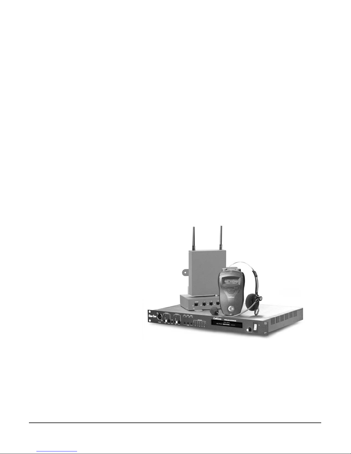
Transceiver/Antenna
Beltpack
Base Station
Figure 1: A CellCom 10 Base Station, Beltpack, and Transceiver/Antenna
The CellCom 10 system consists of three elements:
• Wireless beltpacks,
• A base station that provides routing of communications to and from those
beltpacks, and
• Transceiver/antennas that can be located at intervals remotely from the base
station, providing customized coverage areas where the beltpacks function.
CELLCOM 10 WIRELESS COMMUNICATION SYSTEM
1-1

The CellCom 10 base
station functions as a
full-duplex digital matrix
switcher and router for voice
communications.
In addition, up to six wired full-duplex communications channels, plus program
in and stage-announce out, can all be connected and used simultaneously.
FEATURES
CellCom 10 brings the power of matrix communications to a wireless system,
blended with the coverage flexibility of a local cellular matrix. Features of
CellCom 10 include:
• Ten wireless beltpacks in 1 RU.
• Point-to-point and small group wireless communications.
• Up to six communications routes per beltpack.
• Custom coverage zones with up to ten remote transceiver antennas.
• Transceiver/antennas can be located up to 1,000 meters (3,200 feet) from the
base.
• Five-character labels for each beltpack and connector.
• Customize, name, and assign groups.
• Two party-line and four 4-wire connectors.
• Operates in 1.9 Ghz—above television and other wireless communications.
Each transceiver/antenna
can support
communications with up to
five CellCom 10 wireless
beltpacks operating within
its coverage zone.
• License-free in countries accepting the DECT standard.
• Frequency-hopping DECT technology automatically finds clear spectrum.
• Base functions like a digital matrix; each beltpack has a “virtual port” timeslot.
• Secure system—beltpacks are registered to a particular base and can frequency
hop.
• Two bases can be connected for a 20-beltpack system.
CELLCOM 10 THEORY OF OPERATION
CellCom 10 is quite different from other wireless intercom systems. Wireless
intercoms typically pair individual beltpack transmitters with individual
base-station receivers on the same frequencies, with the resulting signals mixed
and re-transmitted by the base to common receiver boards in the beltpacks –
achieving a wireless party-line.
The CellCom 10 base station functions as a full-duplex digital matrix switcher
and router for voice communications. Within the base, time slots are allocated to
each of the up to 10 wireless beltpacks, each of the full-duplex party-line and
4-wire connectors on the rear panel, the program input / stage-announce output,
and the front-panel intercom headset connector. This technology gives the
advantage of multiple point-to-point and small-group conversations being
possible simultaneously within the system.
1-2
Audio is sampled from each of the headset microphones, is processed and
combined as needed in the CellCom 10 base, and is then sent to each of the
beltpacks and wired connectors in turn. The wireless beltpacks in effect each have
CELLCOM 10 WIRELESS COMMUNICATION SYSTEM
a “virtual port,” as their data and digital audio is sent to and from each beltpack
in a particular time slot.
Each of these beltpacks and wired connections can be named (labeled) with a
unique 5-character alphanumeric designation, and these individual connections
can be combined into groups. All of the rear-panel wired communications
connections can also be labeled. This programming is done via menus within the
base station, and is stored in non-volatile memory.
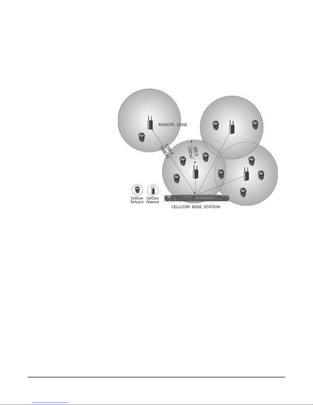
Figure 2: A CellCom 10 Digital Communication System
Each beltpack has a unique “ID” which is registered with the base station and
assigned to a particular time slot. When the base station is turned on and
communicating via its remoted transceiver/antennas, the wireless beltpacks
immediately receive all of their “identity” and communications routing
information from the transmissions from the base – acting as specialized portable
communications terminals. Changes made to the communications routing on
the base are transferred to the beltpacks, so another source can be added to a
group or a talk/listen button on a beltpack can be reassigned in real time.
The wireless link between the base station and the beltpacks is accomplished by
transceiver/antennas that transmit and receive digital data and audio within a
circular coverage area with a maximum radius of 250 meters (about 800 feet)
under ideal conditions, but typically somewhat less depending on location and
obstructions. The base will support up to 10 of these transceiver/antennas, which
can be located throughout a production area to provide seamless coverage for the
wireless beltpacks.
It is also possible to remote one or more of these coverage zones independent of
the others. Transceiver/antennas, which connect with the base station (or via the
antenna splitter to the base) via 4-pair CAT-5 cable, can be positioned up to
1,000 meters (3,200 feet) from the base.
CELLCOM 10 WIRELESS COMMUNICATION SYSTEM
1-3

Each transceiver/antenna can support communications with up to five CellCom
10 wireless beltpacks operating within its coverage zone. As the beltpack user
walks among the coverage zones created by overlapping the coverage of multiple
transceiver/antennas, the communication between that beltpack and the base is
“handed off” to the next transceiver/antenna, without interruption.
If more than five CellCom 10 beltpacks will be operating in a certain coverage
zone, a second transceiver/antenna will be co-located with the first – one per
every five beltpacks working in the particular zone. The theoretical maximum
number of CellCom 10 beltpacks able to be supported in one zone is 50, and the
practical number is between 30 to 35.
The transmissions between the wireless beltpacks and the transceiver/antennas
are done using a customized application of the DECT protocol, operating in the
1.92 to 1.93 GHz band. CellCom 10 can be used without regard to existing
analog and digital UHF television transmissions, wireless mics and in-ear
monitors, and other wireless intercom. Transmissions are digital, and the
technology automatically seeks clear and unused “channels” within the overall
bandwidth allotted to the CellCom 10 system, changing as required by the
immediate circumstances.
Along with the digital nature of the transmission and the random changing of
channels, the unique ID of the beltpack is only registered to the particular
CellCom 10 base. Its transmission is only available to that base, and other
CellCom 10 systems being used in the same vicinity will not “see” it. Therefore,
though the system is not technically “encrypted”, it is virtually impossible to
capture and decipher these transmissions.
CellCom 10 wireless beltpacks can be added to the base rather simply, up to the
maximum of 10 per base. Registration is available through the a software utility,
and a 3.5 mm TRS jack on the beltpack accesses its digital ID. If an existing
beltpack in a system is lost or destroyed, a new unit can be registered in its place;
it will then take on the identity and communications routes of its predecessor.
The CellCom 10 base station also has a variety of connections for adding wired
party-line, digital matrix, and other communications. Two channels of party-line
and 4-channels of 4-wire / digital matrix can be connected via rear-panel
connectors. Each of these may be accessed individually by the wireless beltpacks,
or they may be grouped together in any way desired. Just like the beltpacks, each
of these full-duplex connectors has its own time slot and can be labeled. In
addition, a line-level program input and a line-level stage-announce / paging
output with associated relay is also provided.
DECT TRANSMISSION THEORY
Different that typical FM wireless communications systems, where each
transmitter has a corresponding receiver and is set to a particular frequency (even
in frequency-agile systems), CellCom 10 automatically seeks its own clear
frequencies. CellCom 10 operates in a different frequency band than wireless
microphones, in-ear monitors, and wireless intercoms, and its dynamic channel
selection and allocation capability means that the system does its own frequency
coordination continually while in use. DECT systems in general, and the
1-4
CELLCOM 10 WIRELESS COMMUNICATION SYSTEM

CellCom 10 digital wireless intercom in particular, do not require the frequency
coordination and the intensity of frequency planning that is necessary for FM
systems. Details of the technology are below.
CellCom 10 is based on a specialized application of the DECT (Digital
Enhanced Cordless Telecommunications) standard, which was originally
developed in Europe in the beginning of the 1990’s. It is an open standard for
site-specific radio access in the 1.88 to 1.90 GHz band (enhanced bands up to
1.93 GHz are included), allowing manufacturers to design compliant
technologies that can coexist in a user location and be used without interference
in adjacent locations.
In DECT terminology, the beltpack is called the Portable Part (PP) and the
transceiver/antenna is called the Fixed Part (FP). In essence, this means that the
transceiver/antenna stays in one place, while the beltpacks move with their users.
Each of these units has its own role. The FP creates the coverage zone for the PP,
and the portable part is the user interface, and also takes the initiative in signaling
the fixed part that it is in the coverage zone and seeking to establish and keep a
communications link. CellCom 10 and other DECT-based systems have
multiple fixed parts and portable parts.
DECT uses a Multi-Carrier (MC), Time Division Multiple Access (TDMA),
Time Division Duplex (TDD) radio-access methodology, and combines that
with a continuous Dynamic Channel Selection and Allocation capability.
Basically, it divides up the allocated 20 MHz of spectrum into bands and
channels, uses a fast time clock to sort out the various communications by
assigning each a time slot, and further dividing the time to allow two-way (full
duplex) conversations. To deal with potential interference and conflicts between
these different communications, the technology continually scans for open and
used channels, selecting the best one at any given time that won’t interfere with
other channels already in use.
The result of combining all of these technologies into DECT is that
high-capacity, high-density communications networks can be assembled at a
local level, and can function well even in environments with much RF “traffic.”
DECT is very efficient in finding and using open frequencies without
interference, all without active effort from the user. The fact that these systems
are localized, relatively low-power, and rely on distributed transceivers
throughout the desired coverage area, lead to the term “pico-cellular systems” –
or very small cellular systems.
The 20 MHz spectrum used in a DECT system is divided into 10 carrier
frequencies, which is the multi-carrier portion of the technology. The actual
bandwidth of each carrier is 1.728 MHz. Time, in the form of TDMA, is divided
into time frames that are accessed every 10 milliseconds, each containing 24 time
slots into which a single audio stream may be inserted. In typical consumer
DECT with its more limited audio bandwidth, two time slots are required for a
duplex conversation – one for talk and one for listen.
The special application of CellCom 10 with its better audio bandwidth gives two
time slots for each audio stream (user’s voice), so a full-duplex conversation
requires a total of four time slots. CellCom 10 uses a 2 Mb/s (two megabits per
second) data stream from the base station transceiver ports.
CELLCOM 10 WIRELESS COMMUNICATION SYSTEM
1-5

Doing the math in the case of FreeSpeak Lite, a transceiver/antenna in a given
location selects a particular unused carrier frequency, and uses four time slots for
each full-duplex conversation with a CellCom 10 beltpack. Combined, the five
beltpacks that this transceiver/antenna can support use 20 of the 24 available
time slots (5 times 4). The remaining 4 timeslots are used to support the
recognition and handoff of other beltpacks as they move around and through this
coverage zone, and other related functions.
To support up to 10 beltpacks in a given location, for example, two
transceiver/antennas are placed to operate side by side using different clear carrier
frequencies. Given that these are relatively short-range, localized signals, a carrier
frequency that is being used in one physical location is likely to be clear again in
a nearby location – even within the same overall system installation.
A theoretical maximum of 50 CellCom 10 beltpacks can be used within a given
coverage zone, if 10 transceiver/antennas are co-located together. The practical
limit within a particular zone is in the range of 30 to 35 beltpacks in one zone.
The CellCom 10 transceiver/antennas, via the base station, are continuously
transmitting status and identity information on particular DECT carrier
frequencies, and the CellCom 10 beltpacks are able to receive and analyze that
information. The beltpacks put out a “pulse” at regular intervals to signal their
presence and ID. Through this interchange, the system will determine whether
the beltpack is registered to the base station (and through the base station to the
local transceiver/antenna) and is able to establish a connection.
This method of positive identification that a beltpack “belongs” to a system has
practical benefits in preventing interference or eavesdropping. For example, a
CellCom 10 beltpack whose unique ID is not registered with the particular base
will not be able to establish a communication link with that base. This means
that users of two different CellCom 10 systems that happen to be operating in
the same location – such as a large production event – will not accidentally or
otherwise connect with each others’ systems.
Since the beltpack user is continually moving, often through different coverage
zones created by multiple transceiver/antennas connected with the base station, it
must have a way to measure the strength of the signal connection, and to
establish a connection with the transceiver/antenna offering the highest signal
level. A protocol called RSSI (Received Signal Strength Indication) tells the
beltpack which available signal is both strongest and available to establish a
connection, as it scans through all the available possibilities.
For example, as a beltpack user passes from one coverage zone to another, it is
detecting the signal strength of both transceiver/antennas. Say that an adjacent
transceiver/antenna zone has less than five beltpacks currently connected through
it, so is available for another beltpack. Its signal strength is stronger that the
moving beltpack’s current connection with the other transceiver/antenna by a
threshold amount. In this circumstance, the beltpack will transfer its connection
to the new transceiver/antenna – in a “make before break” type of connection.
1-6
CellCom 10 and other DECT devices also provide security to communications
in several ways. First, the unique ID of a beltpack is registered with the base
station, and it must be recognized and authorized before a communications link
CELLCOM 10 WIRELESS COMMUNICATION SYSTEM

is authorized. Second, the transmission is digital, and does have a ciphering-type
encryption incorporated in the protocol to prevent eavesdropping. Third, the
dynamic changing of carriers and use of time slots means that a particular
conversation cannot be located or locked onto in any meaningful fashion.
CELLCOM 10 WIRELESS COMMUNICATION SYSTEM
1-7

1-8
CELLCOM 10 WIRELESS COMMUNICATION SYSTEM

2
THE CELLCOM 10 BASE STATION
BASE STATION (CEL-BASE)
The CellCom 10 (CEL-BASE) base station provides all of the intelligence and
signal routing for the CellCom 10 digital wireless intercom system. The base
station is effectively a full-duplex digital matrix communications system, with
virtual “ports” for the wireless beltpacks rather than physical ports.
In its memory, the base station contains all of the labels and communications
paths assigned to each CEL-BP beltpack, and this information is sent to the
beltpacks via the CEL-TA transceiver/antennas as soon as they are switched on
and recognized by the base. Through the front-panel display and controls, all
system programming is accomplished.
The base station also functions as the interface between wired and wireless
communication devices. The two party-line intercom connectors, four 4-wire
connectors, and program input/stage-announce output each have their own
full-duplex time slot. They can be labeled, added to communication groups, and
assigned to beltpacks as desired.
BASE STATION FRONT PANEL
2
1
3
4
1 Headset Connector
2 Channel A Talk and Listen Controls
3 Channel A/B Call Switch
4 Channel B Talk and Listen Controls
5 Channels A and B Enable Switches and Lights
Figure 1: CellCom 10 Base Station Front Panel
1
The 4-pin male XLR-type headset socket connects to Clear-Com headsets and
other headsets with 4-pin female connectors. This headset connector is for the
onboard two-channel intercom, with controls just to the right of the connector.
6
5
Headset Connector
7
8
6 Program Audio Enable Switch
7 Wireless Beltpack Light Display
8 Display Screen
9 Scroll/Enter Knob
1
0 Power Switch
10
9
CELLCOM 10 WIRELESS COMMUNICATION SYSTEM
2-1

2
Channel A Talk Switch and Light/Listen Level Knob
The channel A talk switch and associated light, and listen level knob, allow
full-duplex conversations with any CellCom 10 wireless beltpacks or other
communications systems wired to the rear of the base station to which the
onboard Channel A has been assigned. Assignments are done via the front-panel
programming.
The talk switch is momentary/latching, such that pressing it and holding down
will create a talk path that ends when the user releases the switch, while quickly
tapping it will latch the talk, and a second tap will release it. The LED lights red
when a talk is active.
Turning the listen level knob clockwise will allow the user to hear the other
party’s voice, increasing the level to maximum when fully clockwise.
A/B Call Switch (Reserved for Future Use)
3
The A/B call switch does not function. It is reserved for future use.
Channel B Talk Switch and Light/Listen Level Knob
4
The channel B talk switch and associated light, and listen level knob, function
the same as the controls for Channel A.
5
Enable Switch and Lights for Channels A and B
The channel A and channel B enable switches and associated lights activate the
connection on the rear-panel to party-line intercom channels A and B. Activating
one or both of these switches makes duplex communications between the
wireless beltpacks and the wired party-line intercom occur. These switches may
be “locked” via the front-panel SYSTEM programming menu so that they may
not be disengaged accidentally.
Enable Switch and Light for Program Audio
6
This latching switch makes any program audio signal that enters via the
rear-panel line-level 3-pin XLR connector available to be assigned to wireless
beltpacks, either separately or mixed with communications groups. This switch
may be “locked” via the front-panel SYSTEM programming menu so that it may
not be disengaged accidentally.
Wireless Beltpack Light Display
7
These green LEDs, one for each of the ten CEL-BP wireless beltpacks that the
base will support, light when a beltpack is on and connected with the system. For
example, the beltpack that is registered with the base in the BPK03 time slot will
light the LED under number 3 when turned on.
2-2
CELLCOM 10 WIRELESS COMMUNICATION SYSTEM
Display Screen
8
The display screen shows all of the menus and programming options that are
available within the CellCom 10 system. The user can select a particular beltpack
and view all of its current talk/listen assignments, or see all of the current
members of a particular group. Via the screen and rotary encoder, labels
(5-character user names) can be created and/or changed, new members assigned
to groups, input and output levels adjusted, and so on.
Scroll/Enter Knob
9
The scroll/enter knob is used to scroll through the various menu options within
the CellCom 10 base, in order to discover specific information regarding users or
to program communications routes and groups. Turning the knob clockwise
scrolls display items toward the right, and turning the knob counterclockwise
scrolls display items toward the left.
When a desired menu item is highlighted, pushing the scroll/enter knob inward
will select that item. The lists of available beltpacks and groups typically span two
or more screens, so when the highlight is at the leftmost or rightmost part of the
screen and the user continues to turn the rotary encoder in that direction, the
display will jump to the next screen selections [Example: in the beltpack sections,
the first screen shows beltpacks 1 through 5, and the second shows 6 through
10.]. The “BACK” menu button can only be reached by turning the scroll/enter
knob clockwise.
POWER
90-260V, 50/60Hz
80 Watts
1
10
The power switch will turn the CEL-BASE base station on and off.
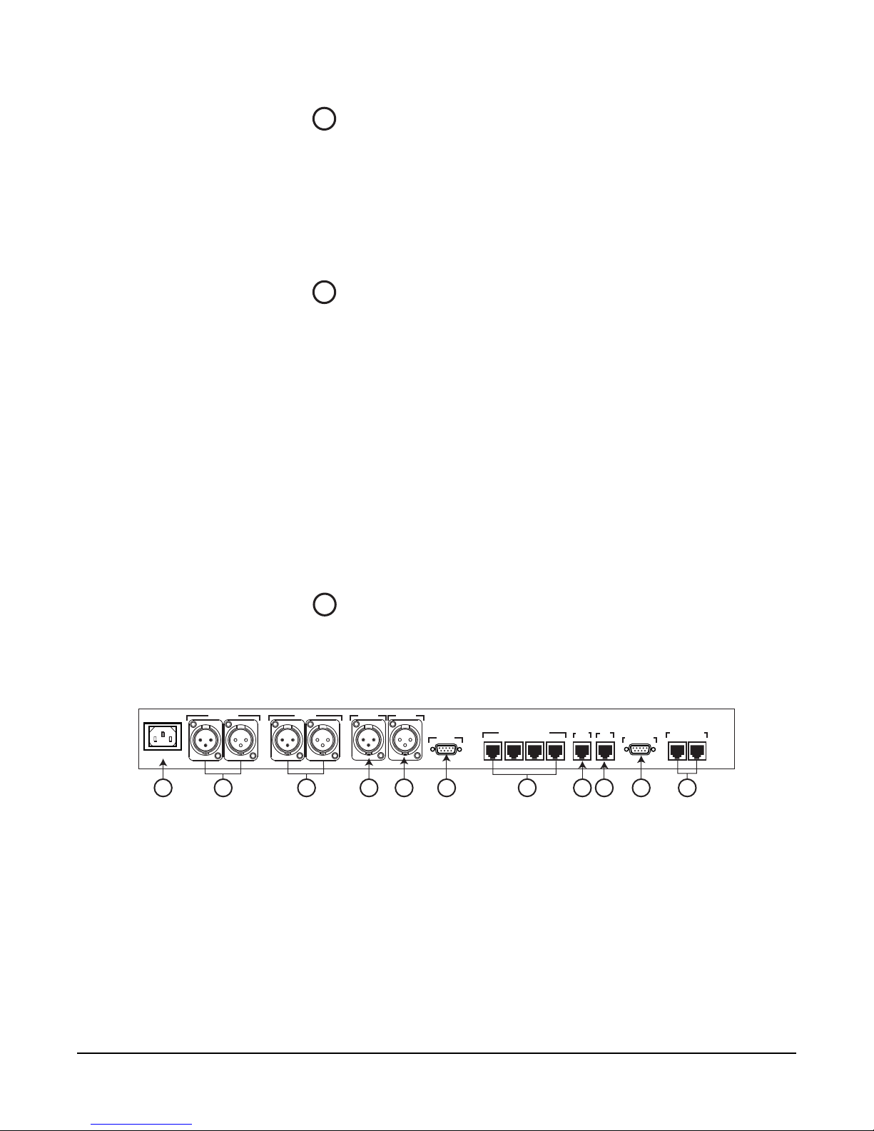
BASE STATION REAR PANEL
PL CH-A PL CH-B
2
1 Power Connector
2 Party Line Channel A Connectors
3 Party Line Channel B Connectors
4 Program Input
5 Stage Announce Output
6 Stage Announce Relay
3
Figure 2: CellCom 10 Base Station Rear Panel
Power Switch
PRGM IN
SA OUT
SA RLY
6
5
4
4-WIRE / ECLIPSE PORTS
1
23
7
7 4-Wire Matrix Ports
8 Base Loop Connector
9 LAN Connector
10 PC Connector
11 Transceiver Connectors
BASE
4
8
PC PROGRAM
9
LAN
LOOP
TRANSCEIVER
1
2
10
11
CELLCOM 10 WIRELESS COMMUNICATION SYSTEM
2-3

IEC Power Connector
1
The 3-conductor AC power connector and universal power supply accepts
voltages from 90 to 250 volts, at 50/60 Hz. Power consumption is 80 watts.
2
Party Line Channel A Connectors
This pair of female and male 3-pin XLR connectors joins a channel of party-line
intercom to the CellCom 10 base station, allowing communication between the
wired system and CellCom 10 wireless beltpacks. Input and Output level control
is set via the front-panel display programming.
The second connector is a loop-through, so that the party-line connection may
be continued to another CellCom 10 base station or to another party-line
beltpack or station. This connector auto-detects a connection with a powered
party-line channel (30-VDC on Pin 2), and the base’s internal 200-ohm
party-line termination and DC voltage to power PL beltpacks is not activated.
Alternatively, when a wired, unpowered party-line beltpack (up to four) is
connected to PL CH-A with standard two-conductor shielded microphone cable,
the base station engages the 200-ohm termination and supplies 24-VDC to the
beltpack(s) – allowing them to operate and communicate with the wireless
beltpacks in the system.
Party Line Channel B Connectors
3
These connectors are the same as those for PL CH-A.
Program Input Connector
4
This female 3-pin XLR connector accepts a line-level audio signal from an
outside source such as a mixing console or audio player. It is transformer-isolated.
Level adjustment is done via the front-panel display programming. The program
input shares a time slot with the stage announce output, described below.
Stage Announce Output Connector
5
This male 3-pin XLR connector allows a line-level audio signal, typically a voice
from a wireless beltpack user, to be sent to a paging system or other audio system.
It is transformer-isolated. Level adjustment is done via the front-panel display
programming. One beltpack at a time can access this output, and it must be
programmed to a CEL-BP. It is activated by pushing the talk on the beltpack
rotary encoder to which the SA Output is assigned.
Stage Announce Relay
6
2-4
This DB-9 male connector provides a relay closure that is triggered
simultaneously with the SA Output. The relay may be used to open an audio
pathway for the signal from the SA Output, or could also be used to activate a
CELLCOM 10 WIRELESS COMMUNICATION SYSTEM
 Loading...