

Page 1
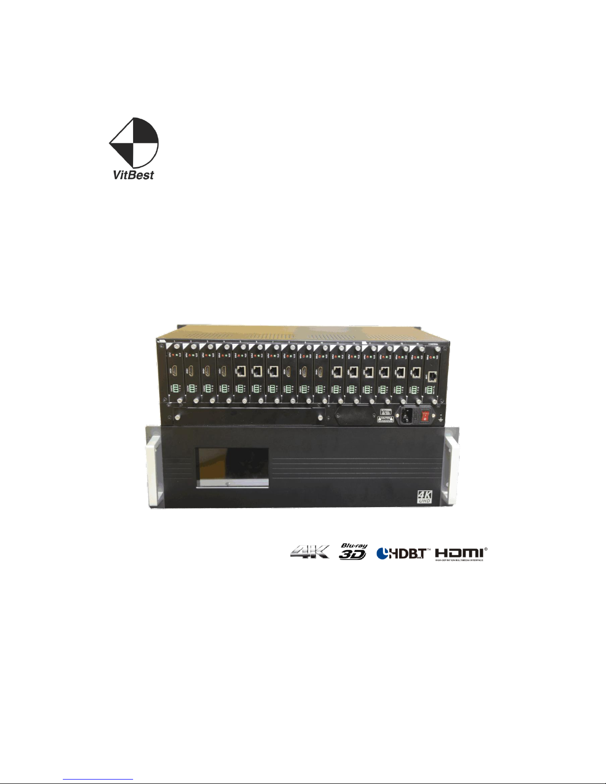
User Manual
(MM4-8C)
(MM4-16C)
Page 2

User manual
operation guide
1、power source
MM4-8C/MM4-16C signal management platform using 100-250v ac voltage power s
upply. Power on when push the button<▍>, Power off when push the button<○>.
2、capacitive touch screen
MM4-8C/MM4-16C signal management platform uses a 5” capacitive touch screen,w
hich have a resolution of 800x480,the layout of system is shown in figure.
Page 3
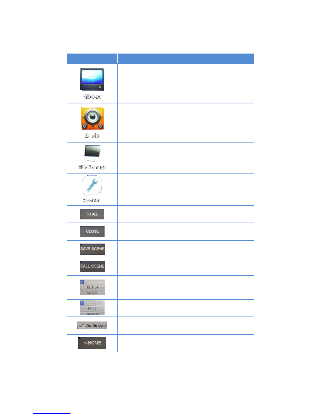
Each particular function button as shown in form
button
function
Video switch select
Audio switch select
EDIE management
System Settings
All switch to select
Close the output channel selection
Save selection key scene
Call select key scenes
Output channel
Input channel
Audio and video synchronization switching
Main interface
Page 4
3、Signal switching
MM4-8C/MM4-16C signal management platform use hot plug input/output card slots;
Slots 13 ~ 16 are fixed to output, slots 1 ~ 12 are configurable for input or outpu
t.
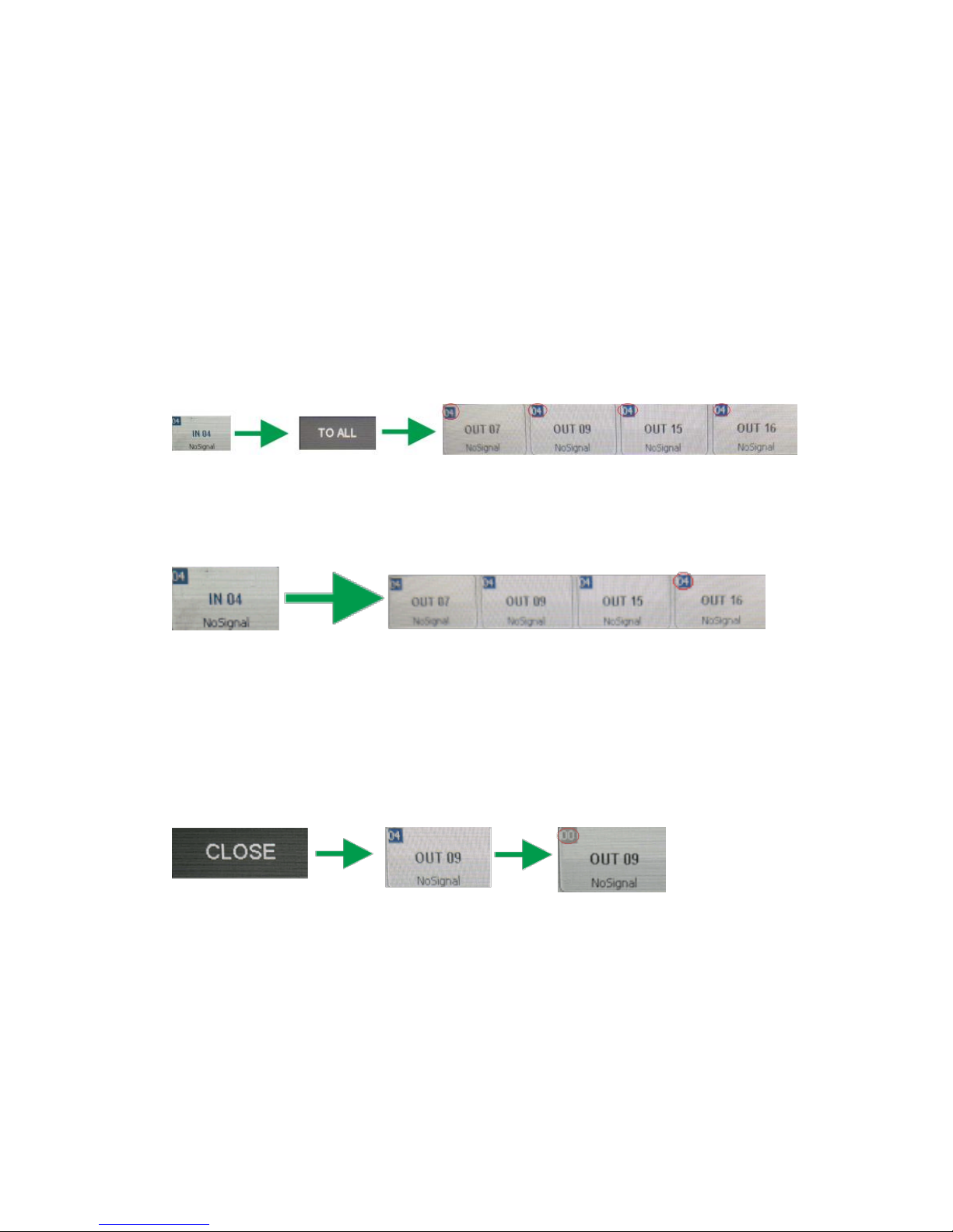
Switch a input to all output channel
Simply choose the Video input and touch the screen interface:touch <Input channel
number> + <TO All>button,input channel number will be displayed in the top left c
orner angle of the output channel.
for example , <IN6> + <TO All> key,Switch successful, at the upper left of the ou
tput channel Angle IN4 will be shown.
Switch any one input to any or all output channels
Select a input andswitchto any output channel. For example , IN4 + OUT7 + OUT
9 + OUT15 + OUT16. Switch successful, IN4 will be shownat the upper left of the
output channel angle.
4、Close the output channel
MM4-8C/MM4-16C signal management platform providesa function of closing a cha
nnel output or multiplex channels output, output channel which was closed will hav
e no signal output. If users need to closean output channel, just click the close but
tonon touch screen, choose the corresponding channel.When close channel success
fully, the output interface on touch screen will become gray, the upper left corner i
nput channel number is 00. Such as the figure below.
5、Check the output channel state
MM4-8C/MM4-16C signal management platform provides a function of checking all
channelsstatus.Can be View the output channel video switchingstatus, Audio switching
status, EDID input channel switchingstatus and output channel identification EDID status,
display equipmentin Videointerface and so on.
For example, audio switching state.
Page 5

6、Scene save and call
Save the current status of input and output channels are also called save the current
scene, MM4-8C/MM4-16C signal management platform supports up to 32 scenes. If the
current status of corresponding video input and output is to be preserved. The capacitive
touch in Video Swicher to <Save scene>+<Storage unit number> . For example, to save
input and output corresponding state 02 unit, <SAVE SCENE> + <Scene 02>.
To invoke the saved scene, <CALL SCENE> + < Storage unit number>, For example, to
invoke the saved in 02 storage unit
7、EDID management
MM4-8C/MM4-16C signal management platform to provide EDID read, reset, storage,
and other functions, the previous generation of signal management platform in the update
Page 6
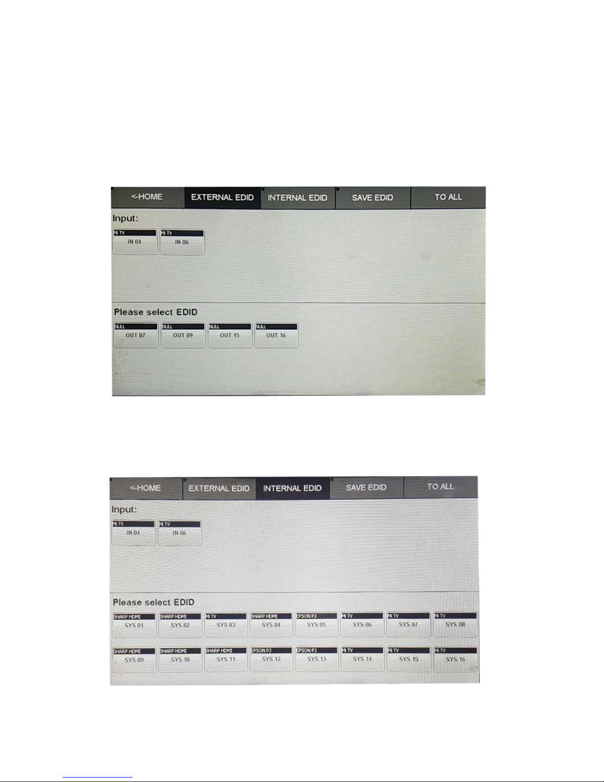
EDID would be more convenient and quick operation.
Each output channel will automatically identify the EDID of display devices, and will
feedback the EDID information corresponding to the touch screen output channel. Update
EDID to input port, also displays the same input EDID information, Updates to the input
port from output EDID. Select EDID switcher, click on the output channel and click need
update EDID input channel. Input channel EDID information same as the output channel
identification EDID. For example, <OUT1> + <IN1>.Output channel 1 EDID information
update to the input channel 1, 2, 3. For example, <OUT1> + <IN1> + <IN2> + <IN3>.
MM4-8C/MM4-16C signal EDID data management platform support store 16 group, may
at any time Save the EDID data updates to the input channel.In an INTERNAL EDID state,
select save EDID, then click on the corresponding input channel
Page 7
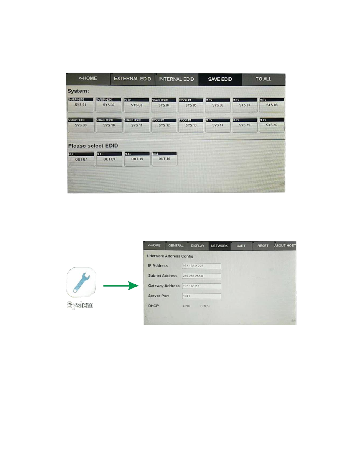
If you need to one output channel EDID information stored. In the SAVE EDID state,
select output to click to save the location of the EDID.
8、Internet network communication Settings
On entering the system Settings menu, select NETWORK menu options. Into the next sub
menu view or change the IP address, protocol, port, setting as shown in the figure.
9、RS232 setting
RS232 communication parameters including Baud Rate, Data Bits, Stop bit, Parity.If you
want to change these parameters can click on the System into the System Settings
menu,elect UART into RS232 Set the Visual Design.
Page 8
10、Version information query
In the system Settings in the options ABOUT HOST to enter submenu interface can see
the Main control board (Main - Version), and the exchange the Back (Back - Version), and
the Version information etc. for example,
11、 system reset
MM4-8C/MM4-16C signal management platform support system restore factory Settings,
and setup system. Elect RESET interface, click on ENTER. for example,
12、RS232 and WAL control command
When MM4-8C/MM4-16C signal management platform and the external control devices
through RS232 connection, and set can be used after the external control Settings to control the
Page 9

operation. RS232 default setting of Baud 115200bps, 8 data bits, 1 stop bit, no parity.
Nu
mb
er
Action
Basic
ASCII
String
Variables
Exampl
e
Settin
gs
Example String
Example
Response
1
Video
switch
input
into
multip
le or
single
channe
l
output
>Catob,c
<CR>
a = input(1 ~
matrix max)
b c = output(1 ~
matrix max or ALL)
Switch
input 1
to
output
2,3
>C1to2,3<CR>
<C1to2,3<C
R>
2
Video
switch
corres
pondin
g
relati
ons
betwee
n
>CRa:b,c
:d<CR>
a c = output(1 ~
matrix max)
b d = input(1 ~
matrix max)
Switch
input 1
to
output
3
Switch
input 2
to
output
4
>CR1:3,2:4<CR>
<CR1:3,2:4
<CR>
3
Video
select
input(
starti
ng up
Off by
defaul
t)
>CSWI:a<
CR>
a = input(1 ~ matrix
max)
Select
input 2
>CSWI:2<CR>
<CSWI:2<CR
>
4
Video
switch
to the
output
>CSWO:a<
CR>
a = output(1 ~
matrix max)
Select
input
the
switch
to the
output
2,3
>CSWO:2,3<CR>
<CSWO:2,3<
CR>
Page 10

5
Video
query
corres
pondin
g
relati
ons
betwee
n
#CR<CR>
NULL
Query
corres
pondin
g
relati
ons
betwee
n
#CR<CR>
<CR1:3,2:4
<CR>
6
Audio
switch
input
into
multip
le or
single
channe
l
output
>Tatob,c
<CR>
a = input(1 ~
matrix max) + A/B
b c = output(1 ~
matrix max or ALL) +
A/B
Note:A=Internal
audio B=External
audio
IN1
video
intern
al
embed
audio
switch
OUT2
intern
al or
extern
al
>T1Ato2A,2B<CR>
<T1Ato2A,2
B<CR>
7
Audio
switch
corres
pondin
g
relati
ons
betwee
n
>TRa:b,c
:d<CR>
a c = output(1 ~
matrix max) + A/B
b d = input(1 ~
matrix max or ALL) +
A/B
Note:A=Internal
audio B=External
audio
Switch
input
1A to
output
2A
Switch
input
1B to
output
2B
>TR1A:2A,1B:2B<
CR>
<TR1A:2A,1
B:2B<CR>
8
Audio
select
input(
starti
ng up
Off by
defaul
t)
>TSWI:a<
CR>
a = input(1 ~ matrix
max) + A/B
Note:A=Internal
audio B=External
audio
Select
input
2A
>TSWI:2A<CR>
<TSWI:2<CR
>
9
Audio
switch
to the
output
>TSWO:a<
CR>
a = output(1 ~
matrix max) + A/B
Note:A=Internal
audio B=External
audio
Select
input
the
switch
to the
>TSWO:3A,3B<CR>
<TSWO:2,3<
CR>
Page 11

output
3A,3B
10
Audio
query
corres
pondin
g
relati
ons
betwee
n
#TR<CR>
NULL
Query
corres
pondin
g
relati
ons
betwee
n
#TR<CR>
<TR1A:3A,2
A:4B<CR>
11
Save
the
scene
>Sa<CR>
a = Scene location
(1~32max)
Save
the
curren
t state
to 10
>S10<CR>
<CR1:3,2:4
,...<CR>
12
Call
scenar
io
switch
>Ra<CR>
a = Scene location
(1~32max)
Call
scenar
io 10
>R10<CR>
<CR1:3,2:4
,...<CR>
13
Switch
the
audio
and
video
synchr
onizat
ion
>SYNC:a<
CR>
a = 0:no
synchronous
1:synchronous
Switch
synchr
onous
>SYNC:1<CR>
<SYNC:1<CR
>
14
Query
the
audio
and
video
synchr
onizat
ion
#SYNC<CR
>
NULL
Query
synchr
onous
#SYNC<CR>
<SYNC:1<CR
>
Page 12

15
Set
the
scene
name
>SNAMEa:
b<CR>
a = Scene location
(1~32max)
b = scene
name(15English
char)
Set the
scene1
0 name
"Meeti
ng"
>SNAME10:Meetin
g<CR>
<SNAME10:M
eeting<CR>
16
Query
the
scene
name
#SNAMEa<
CR>
a = Scene location
(1~32max)
Query
the
scene1
0 name
#SNAME10<CR>
<SNAME10:M
eeting<CR>
17
Set
the
scene
use
>SUSEa:b
<CR>
a = Scene location
(1~32max)
b = scene use(0=no
1=yes)
Set the
scene1
0 use
>SUSE10:1<CR>
<SUSE10:1<
CR>
18
Query
the
scene
use
#SUSEa<C
R>
a = Scene location
(1~32max)
Query
the
scene1
0 use
#SUSE10<CR>
<SUSE10:1<
CR>
19
Uart
switch
>CUARTat
ob,c<CR>
a = RX(1 ~ matrix
max)
b c = TX(1 ~ matrix
max or ALL)
Uart
switch
rx1 to
tx1\2
>CUART1to1,2<CR
>
<CUART1to1
,2<CR>
20
Query
the
all
uart
switch
state
#CRUART<
CR>
NULL
Query
the all
uart
switch
state
#CRUART<CR>
<CRUART1:1
,2:1,...<C
R>
21
Set
the IP
addres
s
>IP:a.b.
c.d<CR>
a b c d =
address(0~255)
set IP
addres
s
192.16
8.2.22
9
>IP:192.168.2.2
29<CR>
<IP:192.16
8.2.229<CR
>
22
Set
the
Subnet
>SUBNET:
a.b.c.d<
CR>
a b c d =
address(0~255)
set
Subnet
255.25
5.255.
0
>SUBNET:255.255
.255.0<CR>
<SUBNET:25
5.255.255.
0<CR>
Page 13

23
Set
the
Gatewa
y
>GATEWAY
:a.b.c.d
<CR>
a b c d =
address(0~255)
set
Gatewa
y
255.25
5.255.
0
>GATEWAY:192.16
8.2.1<CR>
<GATEWAY:1
92.168.2.1
<CR>
24
Set
the
Socket
Server
port
>PORT:a<
CR>
a = Server port
Set the
Socket
Server
port
1001
>PORT:1001<CR>
<PORT:1001
<CR>
25
Set
Networ
k DHCP
>DHCP:a<
CR>
1= 0:no 1:yes
Set
Networ
k DHCP
>DHCP:1<CR>
<DHCP:1<CR
>
26
Query
the
networ
k
inform
ation
#NETWORK
<CR>
NULL
Query
the
networ
k
inform
ation
#NETWORK<CR>
<IP:192.16
8.2.229<CR
>
<SUBNET:25
5.255.255.
0<CR>
<GATEWAY:1
92.168.2.1
<CR>
<PORT:1001
<CR>
27
Set
the
serial
port
>UART:a,
b,c,d<CR
>
a = Baud
Rate(115200 38400
19200 9600)
b = Data bits(8 9)
c = Stop bits(1 1.5
2)
d = Parity
bits(None Odd Even)
Set the
serial
9600,8
,1,Non
e
>UART:9600,8,1,
None<CR>
<UART:9600
,8,1,None<
CR>
28
Query
the
serial
port
#UART<CR
>
NULL
Query
the
serial
port
#UART<CR>
<UART:9600
,8,1,None<
CR>
Page 14

29
Comman
d can
make
>CMDEN:a
<CR>
a = 0:no make
1:make
Set
comman
d can
make
>CMDEN:1<CR>
<CMDEN:1<C
R>
30
Query
Comman
d can
make
#CMDEN<C
R>
NULL
Query
comman
d can
make
#CMDEN<CR>
<CMDEN:1<C
R>
31
Comman
d
notice
sound
>CSOUND:
a<CR>
a = 0:no sound
1:sound
Set
comman
d
notice
sound
>CSOUND:1<CR>
<CSOUND:1<
CR>
32
Query
comman
d
notice
sound
#CSOUND<
CR>
NULL
Query
comman
d
notice
sound
#CSOUND<CR>
<CSOUND:1<
CR>
33
switch
EDID
output
to
input
>EDIDato
b<CR>
a = output(1 ~
matrix max)
b = input(1 ~
matrix max or ALL)
Switch
output
1 to
input 2
>EDID1to2<CR>
<EDID1to2<
CR>
34
switch
EDID
system
to
input
>SYSEato
b<CR>
a = system(1 ~
16)
b = input(1 ~
matrix max or ALL)
Switch
system
1 to
input 2
>SYSE1to2<CR>
<SYSE1to2<
CR>
35
switch
EDID
output
to
system
>SEDIDat
ob<CR>
a = output(1 ~
matrix max)
b = system(1 ~
16)
Switch
output
1 to
system
2
>SEDID1to2<CR>
<SEDID1to2
<CR>
36
Set
the
HDMI
output
format
>HDMODE:
a,b<CR>
a = output(1 ~
matrix max)
b = 0:DVI 1:HDMI
Output
:2 set
HDMI
format
>HDMODE:2,1<CR>
<HDMODE:2,
1<CR>
Page 15

37
Set
card
the
hdcp
switch
>HDCP:a,
b<CR>
a = port(1 ~
matrix max)
b = 0:OFF 1:ON
Set
port:2
the
hdcp
off
>HDCP:2,0<CR>
<HDCP:2,0<
CR>
38
Daught
er
card
power
manage
ment
>CPOWER:
a,b<CR>
a = port(1 ~
matrix max)
b = 0:OFF 1:ON
Close
port 2
power
supply
>CPOWER:2,0<CR>
<CPOWER:2,
0<CR>
39
The
query
card
power
state
#CPOWER:
a<CR>
a = port(1 ~
matrix max)
Query
port 2
power
state
#CPOWER:2<CR>
<CPOWER:2,
0<CR>
40
Set
manage
ment
user
name
and
passwo
rd
>MUNP:a,
b<CR>
a = name(15 the
English
characters)
b = password(15
the English
characters)
ser
user:M
ain
passwo
rd:123
456
>MUNP:Main,1234
56<CR>
<MUNP:Main
,123456<CR
>
41
Query
manage
ment
user
name
and
passwo
rd
#MUNP<CR
>
NULL
Query
manage
ment
user
name
and
passwo
rd
#MUNP<CR>
<MUNP:Main
,123456<CR
>
42
Send
comman
ds to
contro
l card
>COMa<CR
>
a = control card
command
send
"-TEST
"
string
>COM-TEST<CR>
NULL(you
don't
online
returns the
ERROR)
43
Query
whethe
r
centra
l
online
#COM<CR>
NULL
Query
whethe
r
centra
l
online
#COM<CR>
<COM:1<CR>
Page 16

44
To TCP
Socket
server
send
data
>SEND-SS
:a:b,c<C
R>
a = IP
b = Server port
c = data
To
192.16
8.88.1
00:
1001
send
“TEST
”
>SEND-SS:192.16
8.88.100:1001,T
EST<CR>
>SEND-SS:4
<CR>
45
Query
status
inform
ation
Return
ed in
JSON
format
#JSON:a,
b<CR>
a =
("video","scene","
system","weburl","
cont")
b = mark(Status
update version,0 =
Request all data)
Query
the
state
of the
video
>JSON:video,0<C
R>
{
"system":
{
"run":
"Run
000:01:15"
,
"temp":
"20~35",
"ip":
"192.168.8
8.151:8020
",
"wcolor":
"#66ff00",
"mark": 55,
"ahpd": 1,
"uhpd": 1,
"lang": 1,
"update":
true
},
.....
}
Page 17

46
Set
the
system
langua
ge
>LANG:a<
CR>
a = 0:English 1:
Chinese
Set the
system
langua
ge is
Chines
e
>LANG:1<CR>
<LANG:1<CR
>
47
Query
system
langua
ge
#LANG<CR
>
NULL
Query
system
langua
ge
#LANG<CR>
<LANG:1<CR
>
48
Restar
t the
system
>SOF-RES
TART<CR>
NULL
Restar
t the
system
>SOF-RESTART<CR
>
<SOF-RESTA
RT<CR>
49
Restor
e the
factor
y
Settin
gs
>SYS-RES
ET<CR>
NULL
Restor
e the
factor
y
Settin
gs
>SYS-RESET<CR>
<SYS-RESET
<CR>
50
Query
all
the
daught
er
card
types
#RCID<CR
>
NULL(return data
reference link)
Query
all the
daught
er card
types
#RCID<CR>
<RCID:1:I1
,2:N/A...<
CR>
51
Query
main
softwa
re
versio
n
#SVER<CR
>
NULL
Query
main
softwa
re
versio
n
#SVER<CR>
<SVER:1.0.
0<CR>
52
Query
hardwa
re
versio
n
#HVER<CR
>
NULL
Query
hardwa
re
versio
n
#HVER<CR>
<HVER:1.0.
0<CR>
Page 18

53
Query
back
softwa
re
versio
n
#BVER<CR
>
NULL
Query
back
softwa
re
versio
n
#BVER<CR>
<BVER:1.0.
0<CR>
54
Query
matrix
type
#M0<CR>
NULL
Query
matrix
type
#M0<CR>
<MVP-16C<C
R>
55
Query
instru
ction
set
head
#CMD<CR>
NULL
Query
instru
ction
set
head
#CMD<CR>
...
Update time:2017-1-17
> - Command, # - Query, < - Response
<CR> = 0x0D Hex / 13 Decimal
Note: The default communication settings are 115200 8N1 None. IP
address:192.168.88.229 Socket Server port:1001
13、Web management
MM4-8C/MM4-16C signal management platform support Ethernet web management, in
the browser enter the IP address of the MM4-8C/MM4-16C signal management platform,
user name and password login to enter the web management interface. For example,
NOTE:
Page 19

When LAN ports connection if the direct connect. Need to set equipment of IP
network segment and MM4-8C/MM4-16C in the same network segment.
The default user and password for user and 123456.
The factory default Settings segment for 192.168.88.229
WEB management option
Enter into WEB management option can choose video management, audio management,
EDID management, scene calls, system Settings.
(1)、Video switch:switch input channel video signal to output channel, click on the input
channel selection switch output channel or click All switch. For example, input 1 to all the
output channel. Click input 1 to all switch, upper left corner of the output boards display
NI4 channel, said it had four input signal switching to all outlets.
(2)、The input video signal switching to one or more Output , first clicking one input , then
clicking one or more output . The upper right corner of the display corresponds to the input
channel switch said success(3)、Elect Audio sync,when switching the interface audio
and video synchronization switching.
(4)、Clicking , Set interface will pop up the card.
A、Can be set up the board power supply switch.
B、Elect output HDMI\DVI format.
C、HDCP on-off
(5)、Scene save and cal. Elect scene save, then click save channel, scene can be OK.
Page 20

Elect Scene call, then click on the corresponding storage channel before it can be scene
calls out.
(6)、Audio switch: A for internal audio, B for external audio.
①click A, then clicking All switch, for Internal audio switch to both external and internal
①click B, then clicking All switch, for external audio switch to both external and internal
①click A, then clicking A or B, for internal audio switch to A or B.
④ click B, then clicking A or B, for internal audio switch to A or B.
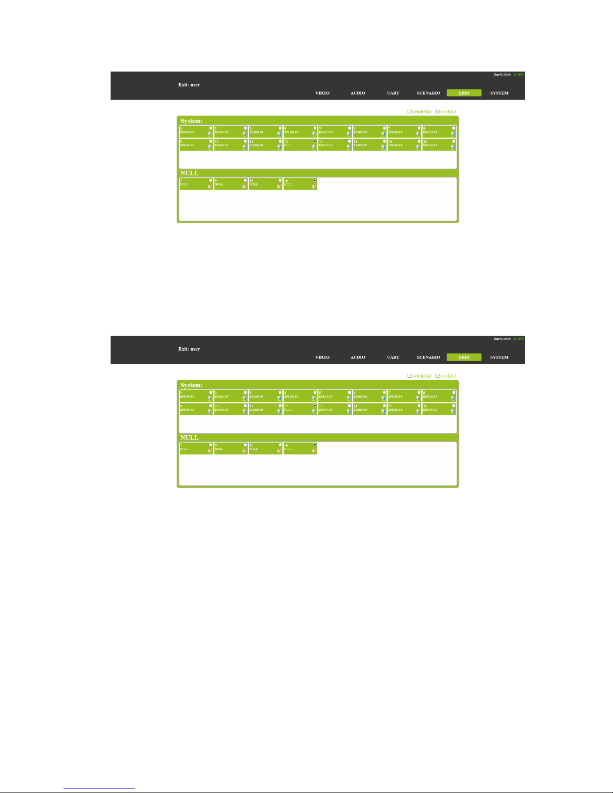
EDID options
(1)、Input EDID for input port save of EDID;
(2)、Please select EDID, for output port read interface display device EDID;
(3)、Internal EDID, for the system built-in save EDID. Most save 16 group EDID.As
shown in figure,
Page 21

(4)、EDID update and save
EDID update: Elect output channel or system EDID option, click input channel will can
EDID switch to input boards. TO ALL will the EDID update to all input board. As shown in
figure,
EDID save:Enter on Save EDID interface, elect output channel EDID, then Select system
save EDID channel. Corresponding storage channel EDID display and output channel
consistent said saved successfully. As shown in figure,
Page 22
UART option
In this option through HDBT input board and HDBT output board of Serial port
communication;It can realize RS232 passthrough control function;first choose RX, then
choose tx contact.
(1)TX:output boards option
(2)RX:input boards option.
As shown in figure,
Page 23

System option
Protect system settings: General settings, Network settings, UART settings, User data,
About host, System Update.
(1)、General:Buzzer, external command, account password to modify Settings.
(2)、Network:IP address, gateway, subnet mask, port, DHCP Settings.
(3)、UART:Baud rate, data bits, stop bits, parity bits.
(4)、USER DATA:Data backup, data recovery.
(5 )、About host : A host name, main control board version number, exchange
back version number, the system updated time to see.
(6)、System Update:The main control board, exchange version, burn card program
As shown in figure,
Page 24

board card guide
MM4-8C/MM4-16C signal management platform for the modular design, the user can
choose different main body, according to the site environment and flexible with different
input and output interface card of a MM4-8C/MM4-16C signal management
platform.MM4-8C/MM4-16C signal management platform support asymmetric
configuration, input and output interface card at the same time, all the input and output
sockets support hot plug function, when the card is abnormal when need to be replaced,
can directly replace, do not affect the normal board.
1、HDBaseT board card
The HDBaseT board card can 16C signal management platform Switch and
compatibility between transmitter and receiver to realize long distance transmission of
audio signals and control signals.Use single CAT 6 cable shielding will transfer to video,
audio, control signal and power supply support furthest 90 m. HDBaseT board card can
the separation of embedded digital audio into analog stereo, support audio embedded
solution, can the independent switch. HDBaseT board card support EDID management
functions and accord with standard of HDCP, and support 1080p/60Hz、1920×1200 and
4K the transmission of signals. Board support bi-directional RS232 passthrough and KVM
functions, can be realized through control channel signal management platform to remote
device control of the equipment.
Technical parameters
The board type
HDBT1 input
HDBT2 input
HDBT1 output
HDBT2 output
Page 25

number/Signal
types
A HDBaseT audio and video signals and control signals
The connector
type
RJ-45 8P line terminal
Recommend the
cable type
STP CAT6/CAT6A and above
1080P Maximum
transmission
distance
≤ 60m
≤ 90m
4KMaximum
transmission
distance
≤ 30m(CAT6A)
≤ 60m(CAT6A)
Support video
standard
HDTV 1080p @60Hz;VESA 1920×1200;4K 30Hz
Support color
space
RGB;YCbCr(4:2:2) YCbCr(4:4:4)
Seamless
switching
No support
EDID management
DDC channels, EDID manager
HDCP
management
Settings HDCPauthorization or not
Board type
HDBT1 input
HDBT2 input
HDBT1 output
HDBT2 output
Audio embedded
support
Port hotplug
support
Power supply
Single channel transceiver power supply DC +28V or standard PSE
Storage
temperature/humid
ity
-20① ~ 85① / 5%~40% RH
Work
temperature/humid
ity
0① ~ 50① / 10%~70% RH
Note
Support RS232 passthrough, terminal blocks, more flow
Appearance of the structure
HDBT1 input/HDBT2input as shown in the figure
Page 26

HDBT1 output/HDBT2 output as shown in the figure
Light is state
light
describe
function
STA
Signal light
Often destroyed — The corresponding channel
no signal input
Normally on - the corresponding channel signal
input
PWR
Power light
Often destroyed - power corresponding
interface card does not work
Normally on - board electricity work accordingly
2、HDMI board card
The HDMI boards interface embedded digital audio separated into analog stereo,
support for audio embedded solution, can independent switch. The HDMI boards support
HDCP standard, support 4K、HDTV 1080p/60、VESA 1920×1200 and below the resolution
of the standard signal input and out.Input board support EDID information update
operations at the same time, can be convenient and fast to solve the problem for EDID
information incompatible problem.
Technical parameters
The board type
HDMI input
HDMI output
number/Signal
types
A HDMI signal
A HDMI signal
The connector
type
HDMI Type A
terminal
HDMI Type A
terminal
Recommend the
cable type
The standard 26AWG HDMI 1.4
Maximum
transmission
distance
≤ 10m
Page 27

Support video
standard
HDTV 1080p @60Hz;VESA 1920×1200;4K
Support color
space
RGB;YCbCr(4:2:2) YCbCr(4:4:4)
Seamless
switching
No support
EDID management
DDC channels, EDID manager
HDCP
management
Settings HDCP authorization or not
Support video
standard
support
Support color
space
support
Seamless
switching
Single channel transceiver power supply DC +28V or standard
PSE
EDID management
-20℃ ~ 85℃ / 5%~40% RH
HDCP
management
0℃ ~ 50℃ / 10%~70% RH
Appearance of the structure
HDMI inputas shown in the figure
HDMI output as shown in the figure
Page 28

Technical parameters
light
describe
function
STA
Signal light
Often destroyed — The corresponding channel
no signal input
Normally on - the corresponding channel signal
input
PWR
Power light
Often destroyed - power corresponding
interface card does not work
Normally on - board electricity work accordingly
System diagram
Page 29

Safety Information
To reduce the risk of electric shock, do not
expose this product to rain or moisture.
Do not modify the wall plug. Doing so will void
the warranty and safety features.
If the wall plug does not fit into your local
power socket, hire and electrician to replace
your obsolete socket.
This equipment should be install near the
socket outlet and the device should be easily
accessible in the case it required disconnection
Warranty
Warranty time is one year and from the date of original shipment.
This warranty shall be void if a serial number has been removed
from the product.
Upon determination of a legitimate defect covered by this
warranty, user should bear the transport cost during the warranty.
If product is out of warranty then repair charge is required.
Minimum repair charge: 10% of the retail price plus the cost of
failed components. We will repair the failed product after repair
cost has been approved by Customers and proper financial
arrangements are made. Customer must cover round trip
shipment expenses.
Return and RMA Policies
Shipments will not be receiver and processed for warranty
repair/replacement without an RMA (Return Materials
Authorization).
 Loading...