

Page 1
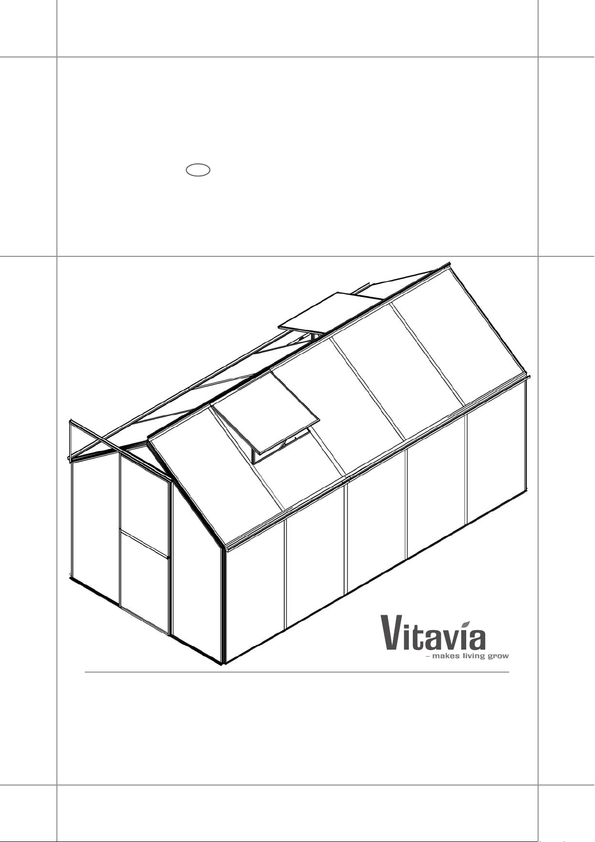
Assembly instructions
D
Montageanleitung
021.01.1109
EOS
3100, 4600, 6000, 7500
Page 2
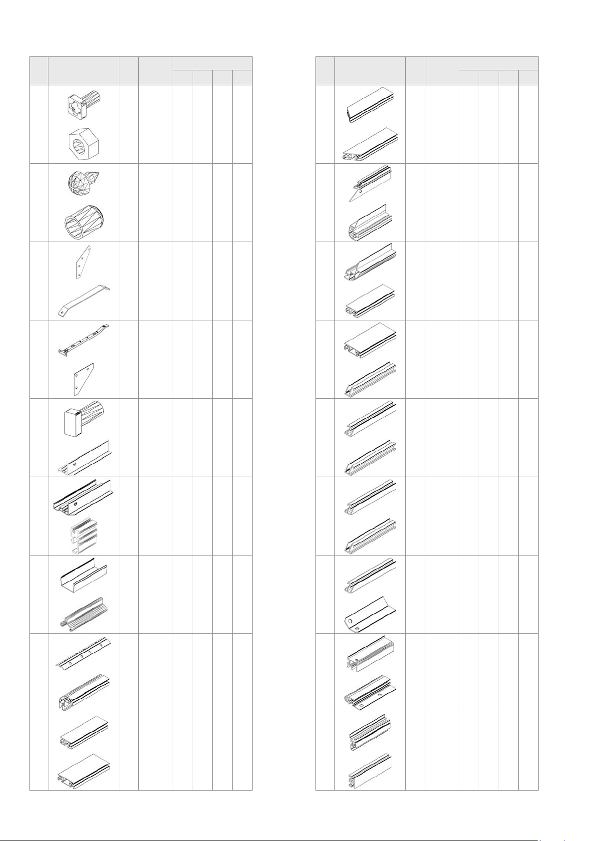
Item
No.
Part
Sect.
Ref.
Size
mm
3100 4600 6000 7500
Quantity
Item
No.
Part
Sect.
Ref.
Size
mm
3100 4600 6000 7500
Quantity
1001
1002
1006
1019
1043
1056
1067
1092
1-8 M6 x 12 112 123 168 179
1-8 M6 115 126 171 182
6-8 3.5 x 6 8 8 18 18
8 15 1 1 2 2
2&4 170 4 4 4 4
5 265 1 2 3 4
8 295 1 1 2 2
1&3 120 4 4 8 8
2235
2236
2237
2240
2241
2242
2243
2244
2&4 1664 2 2 2 2
2&4 1664 2 2 2 2
4 644 1 1 1 1
2&4 1130 2 2 2 2
2&4 1130 2 2 2 2
5 1120 2 4 4 6
5 1120 0 0 2 2
2&4 720 2 2 2 2
2001
2208
2209
2214
2219
2228
2229
2230
7 M6 x 12 3 3 3 3
2 1861 1 1 1 1
3 1861 1 1 1 1
7 14 2 2 2 2
6 100 0 0 2 2
5 80 0 0 1 1
5 200 0 0 1 1
1-2 1227 4 4 4 4
2245
2246
2247
2248
2249
2250
2251
2252
2&4 720 2 2 2 2
2 364 1 1 1 1
2 364 1 1 1 1
4 330 1 1 1 1
4 330 1 1 1 1
7 460 1 1 1 1
4 1260 1 1 1 1
7 1635 1 1 1 1
2231
2232
2 021.01.1109
1 1227 2 4 4 6
1 1227 0 0 2 2
2253
2254
7 584 1 1 1 1
7 584 1 1 1 1
Page 3
Item
No.
Part
Sect.
Ref.
Size
mm
3100 4600 6000 7500
Quantity
Item
No.
Part
Sect.
Ref.
Size
mm
3100 4600 6000 7500
Quantity
2255
2257
2258
2262
2270
2271
2280
2281
7 584 1 1 1 1
7 23.5 1 1 1 1
7 1635 1 1 1 1
8 621 2 2 4 4
7 1635 2 2 2 2
7 37 2 2 2 2
2&4 36 2 2 2 2
2&4 36 2 2 2 2
2315
2316
2320
2321
2325
2326
2360
2361
1 1486 2 0 4 2
1 2221 0 2 0 2
5 1486 0 0 2 1
5 2221 0 0 0 1
5 1486 1 0 0 0
5 2221 0 1 0 0
8 748 1 1 2 2
8 735 1 1 2 2
2285
2289
2290
2291
2292
2294
2307
2308
7 20 1 1 1 1
7 3.9 x 34 1 1 1 1
4 622 2 2 2 2
2 1843.5 1 1 1 1
2&4 1295 4 4 4 4
2 554 1 1 1 1
1 1486 2 0 4 2
1 2221 0 2 0 2
2363
2391
2393
2399
6056
8 735 1 1 2 2
8 621 2 2 4 4
1&3 1370.5 4 4 4 4
6 20 3 5 6 8
6 46 2 2 4 4
2310
2311
6 1486 2 0 4 2
6 2221 0 2 0 2
included with glazing
K
9 610 5 5 5 5
3021.01.1109
Page 4

SICHERHEITSVORKEHRUNGEN
1. PLEASE READ THESE INSTRUCTIONS CAREFULLY AND COMPLETELY BEFORE ASSEMBLING YOUR GREENHOUSE.
2. Sharp edges and corners can cause injury. Always wear protective glasses, gloves, shoes and headgear when handling the aluminium proles, glass
and polycarbonate sheets. Broken glass is a safety hazard – always clear up immediately and dispose of with care.
3. The product you have purchased is intended only for the growing of plants and should only be used for this purpose. When used for other purposes we
will take no responsibility.
4. It is recommended that this greenhouse is assembled by two people.
5. Should you encounter difculties constructing this house or in positioning the polycarbonate sheets, please contact your retailer
– do not use force!
6. The greenhouse must always be anchored.
Safety Warning
Assembly Instructions
SITE SELECTION
Always try to select a sunny location, sheltered
from the wind as much as possible.
IMPORTANT
Before assembling your new greenhouse,
please check that all parts in the provided list
are included. Please take each bundle out of
the packaging in order to identify the parts
better.
It is important that the opened bundles do not
get mixed with one another.
If something is missing please contact your
retailer.
Nuts (1002) - Max. tightening torque 3Nm.
Important! The UV-resistant side of the poly-
carbonate panes is indicated by a plastic folio
or printing at the edge. This side must face
outside. Remove the plastic folio.
NECESSARY TOOLS
Screw drivers (Normal and Crosshead PH2),
10 mm socket spanner or wrench, 10 mm
combination spanner, knife, measuring stick,
spirit level, Accu-drill with adjustable torque.
MAINTENANCE
The greenhouse should be thoroughly washed
with a gentle detergent occasionally. Please
check that the detergent used does not react
aggressively with aluminium or plastic.
Ensure that the door tracks are cleaned regularly to avoid a build up of debris
0. BASE
Important! The base must be square and
level. A zinc-coated steel base is available as
an accessory for all greenhouse models.
(Attention! Only when the greenhouse has to
be located in a very windy and unprotected
location: Drill through both the prole at the
base of the greenhouse and the steel base,
and connect them with nuts and bolts.)
If you would rather construct your own stone
or concrete foundation, please follow the
dimensions specied in diagram 0.
Treated wooden beams at least 18mm high
and not more then 32mm wide should be positioned between the stone/concrete foundation
and the aluminium frame, and connected
to the foundation with 50mm long bolts (not
provided).
Foundations must extend down below the frost
level.
Diagrams in a single frame show the view
from inside the greenhouse. Those enclosed in a double frame show the view from
outside the greenhouse.
1. SIDE ELEMENTS
Lay all of the parts on the oor and connect
them loosely. (1.1) to (1.6)
Note: All bolt heads must slide into the bolt
channels in each vertical bar.
Note: The position of the corner bars (2230)
used should correspond to the front of the
house. The two sides will be a mirror image of
one another.
2. PLAIN GABLE END
Lay the parts (2208), (2230), (2235), (2236),
(2291) and (2292) on the oor and connect
them loosely, (2.2) (2.3) (2.8).
Slide panes A, B and C into the appropriate
guides in the vertical bars (2.4).
Position (2280) / (2281) on the relevant corner
bar (2230)
Connect (2244) / (2246) to the outside of roof
.
corner bar (2240) and (2245) / (2247) to the
outside of (2241) (2.6)
Loosely connect corner plate (1043) to (2240)
and (2241) (2.5).
Connect the assembled roof corner bars over
the assembled panes (2.7) (2.9), taking care to
position (2280) and (2281) as shown
3. CONNECTING THE SIDE ELEMENTS
Insert 2 extra bolts into each roof corner bar
(2240) and (2241) (3.3) (3.4).
[Eos 3100: Insert an extra bolt in (2240) or
(2241) to later connect roof vent sill bar (2360)
on the desired side.
Bolt the side elements to the plain gable end
(3.1) (3.2).
Allow one of the extra bolts in (2240) and
(2241) to slide into the open hole in corner
angle (2315/2316) (3.4) (3.5).
Note: Position (2240) and (2241) using the
locating edge on (2315/2316).
Connect the front sill bar (2209) to corner bars
(2230) (3.6).
Connect back side brace (2393) (3.5) (3.7).
4. DOOR GABLE END
Assemble the front middle bars (2235) (2236)
and braces (2290) (2292) (4.3) (4.4) (4.5).
Slide panes A and C into the appropriate
guides in the vertical bars (4.2).
Position (2280) / (2281) on the relevant corner
bar (2230)
Connect (2244) / (2248) to the outside of roof
corner bar (2240) and (2245) / (2249) to the
outside of (2241) (4.6)
Insert 2 extra bolts into each roof corner bar
(2240) and (2241) (4.7) (4.8).
Connect the assembled roof corner bars over
the assembled panes, taking care to position
(2280) and (2281) as shown
Loosely connect corner plate (1043) to (2240)
.
.
.
]
.
.
4
021.01.1109
Page 5

and (2241) (4.7) and allow one of the extra
bolts in (2240) and (2241) to slide into the
open hole in corner angle (2315/2316) (4.7).
Note: Position (2240) and (2241) using the
locating edge on (2315/2316).
Place pane D into the guide in horizontal bar
(2237) and assemble onto (2240 and (2241)
(4.8) ensuring correct tting into (2248) and
(2249)
.
Connect door guide bar (2251) to horizontal
bar (2237) loosely from the outside with two
nuts and bolts
.
Depending on which direction the door should
open, align the door guide bar (2251) to the
left or to the right.
5. ROOF ASSEMBLY
[Eos 6000 & 7500:
Assemble parts (2320) / (2321) together using
connecter (2229) and 8 nuts and bolts (5.1).
Note: The 4 inside nuts and bolts should only
be connected loosely.
Slide part (2228) (5.2) over the join between
the ridge bars.
]
Connect the assembled ridge bar (2320 -
2326) onto roof corner bars (2240) and (2241)
by sliding the prepared extra bolts into the
open hole in the ridge bar (5.3).
Insert 1 extra bolt to connect roof brace (1056)
into each roof middle bar (2242) (5.7) and
(2243) (5.8).
On two adjacent roof bars insert 1 extra bolt to
connect roof vent sill bar (2360) in step 6.
[Eos 6000 & 7500: Please repeat this at a second
location.
]
[Eos 3100: Include 1 extra bolt adjacent to that
included in (2240) / (2241) in step 3.
]
Connect roof middle bars (2242) and (2243)
between the eave angle bars, noting the
locating edge (5.4), (5.5) (5.6) and the ridge
bar (5.7) (5.8).
Now position your frame on the prepared
base/foundation and connect loosely. (Please
only tighten these bolts after the house is fully
glazed.) Adjust the frame until it is completely
square and tighten all bolts.
Please do not over tighten (max. 3Nm).
6. SIDE / ROOF GLAZING
[Eos 6000 & 7500: Slide eave connecter (2219)
into the joining ends of eave bars (2310) or
(2311) (6.2). On both sides of (2219) connect
screw (1006) in the prepared holes (6.2).
]
Slide panes E into the appropriate guides in
the vertical bars (6.4).
Slide panes F and G into the appropriate
guides in the roof bars (6.5).
Prepare 4 bolts in each eave bar and connect
to eave angles (2315) or (2316) (6.6) (6.7).
Connect roof vent xers (6056) to sill bar
(2360) using screws (1006) (6.8). Connect
(2360) in the desired opening for the roof vent
tting it over the top edge of the assembled
pane G (6.9).
Push spacer (2399) onto the ridge bar, in the
middle of each eld, to ensure roof panes F
maintain the correct distance.
7. DOOR
Attention: Do not stand the assembled door
on door gliders (2214) to avoid damaging
them.
Screw (1006) into both sides of door bottom
bar (2255) and then push door gliders (2214)
into both ends (7.2).
Assemble (2252), (2253), (2254) and (2255)
as shown (7.3) (7.4) (7.5).
Slide the panes H into the appropriate guides
in the middle bars and connect door side bar
(2258) (7.6).
Insert door guides (2271) into the top end of
door side bars (2252) and (2258) (7.5).
Slide brush seal (2270) into both side bars
(2252) & (2258) (7.7).
Slide (2214) onto sill bar (2209) and (2271)
into door guide bar (2251) as shown.
Cutting brush seal (2270) on the desired side,
use screw (2289) to connect door knob (2285)
as shown.
Connect (2257) to door support bar (2250)
using bolt (2001). Connect (2257) to the end
of (2251) by inserting bolt (1001) in the bolt
channel in (2251) (7.8).
Connect the bottom end of (2250) to corner
bar (2230) by inserting bolt (2001) into the bolt
channel in (2230) (7.9).
Once the door is in place connect nut (1002)
and bolt (2001) into the open end of (2251) as
door stopper.
8. ROOF VENT
Connect roof vent bars (2262) and (2361)
(8.2).
Slide pane J into the apropriate guides (8.3)
and connect bottom bar (2363) (8.4).
Attach roof vent opener (1067) using screws
(1006) and place plastic cap (1019) over the
end (8.5).
Position the roof vent in the ridge bar from one
end (8.6) (8.7) (8.8) and slide it to the prepared opening (8.9).
9. SPLIT PANE GLAZING
If your greenhouse is delivered with split
panes then the connecting H-plastic (K) can
be found with the glazing. Please cut them to a
length of 584mm so that they t between the
aluminium proles.
FINISHING
If desired, it is possible to seal the greenhouse
at the edges using neutral silicone. Silicone is
not in cluded.
Place the warning label inside the house.
A full range of greenhouse accessories, to
help you make the most of this product, is
available from your stockist. Please inform
yourself as to the possibilities.
SAFETY NOTICE
In the event of high wind conditions, close the
doors and all vents.
In the event of heavy snowfall, clear the roof
of the building or take suitable measures to
support the roof. Heat the building in winter.
COMMENTS
For the complete protection of your new
green house, we advise you to include it in
your house insurance. Please take note
of possible building rules relating to the
positioning of greenhouses.
Please stick the included greenhouse model
label onto door bar (2253) after success fully
assembling this product. This information is
important in the event that replacement parts
are later required.
Please keep these assembly instructions in a
safe place, for future reference!
Our policy is one of continuous improvement
and we reserve the right to change the specications without prior notice.
5021.01.1109
Page 6

Sicherheitsvorkehrungen
1. BITTE LESEN SIE DIESE MONTAGEANLEITUNG VOR BEGINN DES AUFBAUS KOMPLETT DURCH!
2. Bei der Handhabung von Glas, Polycarbonatplatten oder Gewächshausteilen sind immer eine Schutzbrille, Handschuhe, Sicherheitsschuhe und ein
Kopfschutz zu tragen, da scharfe Kanten zu Verletzungen führen können. Gebrochenes Glas ist ein Sicherheitsrisiko. Beseitigen Sie es mit der
gebotenen Vorsicht.
3. Das von Ihnen erworbene Produkt ist für die Aufzucht von Panzen konstruiert und sollte auch ausschließlich dafür genutzt werden. Bei anderweitiger
Nutzung ist jegliche Haftung ausgeschlossen.
4. Für die Montage dieses Produktes sind zwei Personen erforderlich.
5. Sollten Sie beim Montieren des Hauses oder beim Einsetzen der Verglasung Schwierigkeiten haben, dann setzen Sie sich bitte mit Ihrem Händler in
Verbindung – Wenden Sie keine Gewalt an!
6. Das Gewächshaus muss verankert werden.
Aufbaubeschreibung
STANDORTWAHL
Suchen Sie den sonnigsten, aber gleichzeitig
einen windgeschützten Platz aus.
WICHTIG
Bevor Sie mit der Montage Ihres Gewächs-
hauses beginnen, überprüfen Sie, ob alle in
der Liste aufgeführten Teile vorhanden sind.
Nehmen Sie die einzelnen Bündel aus der
Verpackung, um sie besser identizieren zu
können. Es ist wichtig, dass die geöffneten
Bündel nicht durcheinander geraten.
„Leerschraube“ = Schraube und Mutter für die
spätere Befestigung von Teilen, vorerst ohne
sichtbare Funktion.
Sollte trotz sorgfältigster Prüfung etwas fehlen,
dann setzen Sie sich bitte mit Ihrem Lieferanten in Verbindung.
Muttern (1002) mit max. 3Nm anziehen.
Wichtig! Die UV- beständige Seite der Hohl-
kammerplatten ist durch eine Plastikfolie oder
einen gedruckten Hinweis an den Kanten gekennzeichnet. Diese Seite muss nach außen
zeigen! Entfernen Sie die Folie.
BENÖTIGTE WERKZEUGE
Schraubendreher (Schlitz und Kreuzschlitz
PH2), 1 Schraubenschlüssel 10 mm, RingGabelschlüssel, Messer, Zollstock, Wasserwaage, Akku-Schrauber mit einstellbarem
Drehmoment.
WARTUNG
Das Gewächshaus sollte hin und wieder
gründlich mit einer neutralen Waschmittellauge
abgewaschen werden. Das Glas kann mit
einem Reinigungsmittel gesäubert werden,
das weder Kunststoffteile, den Aluminiumrahmen, noch die Glasfederklammern angreift.
Reinigen Sie regelmäßig die Türlaufschiene.
0. FUNDAMENT
Wichtig! Das Fundament muss absolut recht-
winklig und eben sein. Ein verzinktes
Stahlfundament ist für alle Gewächshaus-
Modelle als Zubehör erhältlich.
(Achtung! Nur wenn das Gewächshaus an
einer sehr ungeschützten und windigen Stelle
aufgebaut werden muss: Durchbohren Sie die
Grundprole und das Stahlfundament und
verschrauben Sie beide mit Schrauben und
Muttern miteinander)
Wollen Sie jedoch selbst ein Fundament aus
Stein oder Beton fertigen, dann richten Sie
sich bitte nach den Maßangaben im Abschnitt
0. Vorbehandelte witterungsgeschützte Holzleisten von mindestens 18 mm Dicke und
höchstens 32 mm Breite werden zwischen
Stein-Betonfundament und Aluminiumrahmen
gesetzt, entsprechend der Zeichnung durchbohrt und mit 50 mm langen Schrauben (nicht
mitgeliefert) im Fundament verschraubt.
Das Fundament muss frostfrei gegründet werden.
Alle Zeichnungen sind von der Innenseite
des Hauses gesehen abgebildet, mit Ausnahme der Abbildungen, die in einem Doppelrahmen dargestellt sind, diese beschreiben die Außenansicht.
1. SEITENWÄNDE
Alle Teile auf dem Boden auslegen und lose
verschrauben (1.1) bis (1.6).
Achtung: Die Schraubköpfe müssen in die
jeweiligen Schraubenkanäle eines jeden
Vertikalprols geschoben werden.
Achtung: Die Eckprole (2230) werden an
der Giebelseite mit Tür benötigt! Die beiden
Seiten sollten jeweils spiegelverkehrt montiert
werden.
2. GIEBELENDE OHNE TÜR
Die Teile (2208), (2230), (2235), (2236), (2291)
und (2292) auf den Boden legen und lose
verschrauben (2.2) (2.3) (2.8). Die Scheiben
A, B und C in die passenden Führungen der
Vertikalprole schieben (2.4).
(2280) / (2281) auf dem entsprechenden
Eckprol positionieren (2230)
(2244) / (2246) an der Außenseite des DachEckprols (2240)verschrauben und (2245) /
(2247) an der Außenseite von (2241) (2.6)
Das Eckblech (1043) lose am äußeren Ende
der Giebelprole (2240) und (2241) (2.5)
verschrauben.
Die montierten Dach-Eckprole über den
eingesetzten Scheiben (2.7) (2.9)
verschrauben und dabei auf die Position von
(2280) und (2281) achten.
3. ZUSAMMENBAU DER
SEITENELEMENTE
2 zusätzliche Leerschrauben in jedes
Dach-Eckprol (2240) und (2241) (3.3) (3.4)
schieben.
[Eos 3100: Eine zusätzliche Leerschraube in
(2240) oder (2241) schieben für die spätere
Verschraubung des Dachfensterschwellenpro-
ls (2360) auf der gewünschten Seite.
Verschrauben Sie beide Seitenelemente mit
dem Giebelende ohne Tür (3.1) (3.2).
Schieben Sie eine der Leerschrauben in
(2240) und (2241) um in die offene Bohrung
im Traufenprol zu gelangen (2315 / 2316)
(3.4) und (3.5).
Achtung: Die Dach-Eckprole (2240) und
(2241) an der Anlegekante von (2315) und
(2316) positionieren.
Das Bodenprol (Türseite) (2209) an den
Eckprolen (2230) (3.6) befestigen.
Die hintere Diagonalstrebe (2393) montieren
(3.5) (3.7).
4. GIEBELSEITE MIT TÜR
Die vorderen mittleren Prole (2235) (2236)
und Streben (2290) (2292) (4.3) (4.4) (4.5)
verschrauben.
Die Scheiben A und C in die passenden Füh-
rungen der Vertikalprole schieben (4.2).
(2280) / (2281) auf dem entsprechenden
.
.
]
6
021.01.1109
Page 7

Eckprol positionieren (2230) .
(2244) / (2248) an der Außenseite des DachEckprols (2240) verschrauben und (2245) /
(2249) an der Außenseite von (2241) (4.6)
Schieben Sie 2 Leerschrauben in jedes Dach-
eckprol (2240) und (2241) (4.7) (4.8).
Die montierten Dach-Eckprole über den
eingesetzten Scheiben verschrauben, dabei
auf die Position (2280) und (2281) achten, wie
gezeigt
.
Das Eckblech (1043) locker mit (2240) und
(2241) (4.7) verschrauben und eine der Leerschrauben in (2240) und (2241) für das offene
Langloch im Traufenprol (2315 / 2316) (4.7)
verwenden.
Achtung: (2240) und (2241) mit Hilfe der
Anlegekante im Traufenprol (2315 / 2316)
montieren.
Scheibe D in die Horizontalstrebe (2237)
einsetzen und an (2240) und (2241) (4.8)
montieren und sicherstellen, dass sie richtig in
(2248) und (2249)
Die Türführungsschiene (2251) lose von
außen mit zwei Schrauben und Muttern an das
Horizontalprol (2237) schrauben
Je nachdem, in welche Richtung sich die Tür
öffnen soll, die Türlaufschiene (2251) nach
links oder rechts ausrichten.
5. ZUSAMMENBAU DES DACHES
[Für Eos 6000 & 7500:
Zusammenbau der Teile (2320) / (2321) mit
Hilfe eines Verbindungsstückes (2229) und 8
Schrauben und Muttern (5.1).
Achtung: Die 4 inneren Schrauben und Muttern sollten nur lose verschraubt werden.
Das Teil (2228) (5.2) über die Verbindung
zwischen den Firstprolen schieben.
Das montierte Firstprol (2320 - 2326) an
den Dach-Eckprolen (2240) und (2241)
verschrauben, indem die dafür vorgesehenen
Leerschrauben in das Langloch im Firstprol
(5.3) geschoben werden.
Eine Leerschraube zur Verschraubung der
Windstrebe (1056) in jedes mittlere Dachprol
(2242) (5.7) und (2243) (5.8) schieben.
An zwei benachbarten Dachstreben eine
Leerschraube einfügen zur Verschraubung
des Dachfensterschwellenprols (2360) in
Schritt 6.
[Eos 6000 & 7500: Bitte dies für eine zweite
Dachfensterschwelle wiederholen.
[Eos 3100: Eine zusätzliche Leerschraube
neben denen in (2240) / (2241) in Schritt 3
enthaltenen hinzufügen.
Die mittleren Dachprole (2242) und (2243)
zwischen den Traufen-Eckprolen verschrau-
ben, dabei die Anlegekante beachten (5.4)
(5.5) (5.6) und am Firstprol auf Stoß montieren. (5.7) (5.8).
Das soweit zusammen geschraubte Gewächshaus auf das Fundament setzen und lose
mit dem Fundament verschrauben.(Bitte diese
Schrauben erst fest anziehen, wenn das Haus
komplett verglast ist). Am Ende das Haus
passt.
]
.
.
]
]
justieren, bis es komplett rechtwinklig ist und
dann alle Schrauben fest anziehen.
Die Schrauben müssen fest, aber nicht zu
fest angezogen werden (max. 3Nm).
6. SEITEN / DACHVERGLASUNG
[Eos 6000 & 7500: Traufenverbinder (2219) in
die Enden der Traufenprole schieben (2310)
oder (2311) (6.2). Auf beiden Seiten der (2219)
mit Schrauben (1006) in den vorbereiteten
Bohrungen verschrauben (6.2).
Die Scheiben E in die entsprechenden Füh-
rungen der vertikalen Prole einsetzen (6.4).
Die Scheiben F und G in die entsprechenden
Führungen der Dachprole einsetzen (6.5).
4 Schrauben in jedes Traufenprol einsetzen
und mit den Traufenwinkeln (2315) oder
(2316) (6.6) (6.7) verschrauben.
Einrastzapfen (6056) mit den Schrauben
(1006) an dem Schwellenprol (2360) befesti-
gen (6.8). Das Schwellenprol (2360) in der
gewünschten Öffnung für das Dachfenster
einpassen und bündig über dem oberen Rand
der eingesetzten Scheibe G verschrauben
(6.9).
Den Abstandshalter (2399) auf das Dachrstprol in die Mitte des Feldes drücken um si-
cherzustellen, dass der korrekte Abstand der
Dachscheiben F erhalten bleibt.
7. TÜR
Achtung: Niemals die montierte Tür auf die
Türgleiter (2214) stellen.
Die Schrauben (1006) in beide Enden des
unteren Türprols (2255) hineinsetzen und
dann die Türgleiter (2214) in beide Enden
(7.2) hineindrücken.
(2252), (2253), (2254) und (2255) verschrauben wie in (7.3) (7.4) (7.5) gezeigt.
Die Scheiben H in die entsprechenden Füh-
rungen der mittleren Prole schieben und das
Türseitenprol (2258) (7.6) montieren.
Die Türführungen (2271) in das obere Ende
der Türseitenprole (2252) und (2258) (7.5)
hineinschieben.
Die Bürstendichtung (2270) in beide Seiten-
prole (2252) und (2258) (7.7) hineinschieben.
Türgleiter (2214) auf das Schwellenprol
(2209) und (2271) und in die Türführungsschiene (2251) schieben, wie gezeigt.
Die Bürstendichtung (2270) auf der gewünschten Seite abschneiden, Schraube (2289) zum
Verschrauben des Türgriffs (2285) verwenden.
Den Befestigungswinkel (2257) mit der
Schraube (2001) an der Türspurstütze (2250)
verschrauben. Dann (2257) durch Einsetzen
der Schraube (1001) in den Schraubenkanal
der Türlaufschiene (2251) am Ende verschrauben (7.8).
Das untere Ende von (2250) mit dem Eckprol
(2230) durch Einsetzen der Schraube (2001)
in den Schraubenkanal in (2230) (7.9)
verbinden.
]
Nachdem die Tür eingesetzt ist, die Schrauben (2001) und Muttern (1002) als Türstopper
an die beiden Enden der Türschiene (2251)
montieren.
8. DACHFENSTER
Dachfensterprole (2262) und (2361) (8.2)
verschrauben.
Scheibe J in die entsprechenden Führungen
schieben (8.3) und das untere Fensterprol
(2363) (8.4) verschrauben.
Den Dachfensteraufsteller (1067) mit Schrau-
ben (1006) montieren und Kunststoffkappen
(1019) über das Ende (8.5) ziehen.
Das Dachfenster vom Firstende aus in den
First einführen (8.6) (8.7) (8.8) und in die vorgesehene Position bringen (8.9).
9. GETEILTE HKP
Wenn Ihr Gewächshaus mit geteilten Schei-
ben geliefert wird, nden Sie die H-Prole aus
Kunststoff (K) bei der Verglasung. Bitte auf
eine Länge von 584 mm schneiden, so dass
sie zwischen die Aluminiumprole passen.
DIE LETZTEN HANDGRIFFE
Bei Bedarf können Sie das Gewächshaus an
vorhandenen Fugen mit Silikon abdichten. Das
Silikon gehört nicht zum Lieferumfang.
Den beiliegenden Warnaufkleber von innen
aufkleben.
Ihr Lieferant hält ein reichhaltiges Sortiment an
Gewächshaus-Zubehör für Sie bereit. Sprechen Sie ihn an.
SICHERHEITSHINWEIS
Bei starkem Wind sollten alle Öffnungen und
die Tür geschlossen werden.
Dächer von Gewächshäusern sind so rechtzei-
tig von Schnee zu räumen, dass keine gefährliche Schneebelastung eintreten kann.
ANMERKUNGEN
Zum vollen Schutz des Gewächshauses empfehlen wir, es mit in Ihre Hausversicherung
einzuschließen. Beachten Sie eventuell vorhandene örtliche Bauvorschriften.
Den mitgelieferten Typaufkleber nach erfolgter
Montage des Gewächshauses auf das Radgehäuse (2253) kleben.
Die Typbezeichnung benötigen Sie zur Angabe bei der Bestellung evtl. benötigter Ersatzteile. Bitte heben Sie die Montageanleitung
auf!
Alle Maßangaben sind Annäherungswerte.
Änderungen vorbehalten.
021.01.1109
7
Page 8

0
30 x 20 mm
B
X = X
30 mm
30 mm
A
3100 4600 6000 7500
A 1529 mm 2264 mm 3015 mm 3750 mm
B 1904 mm 1904 mm 1904 mm 1904 mm
EOS
DIANA
8
021.01.1109
Page 9

3100 4600
1001
2x7 2x9
3100
1x
1x
2315
1A
1.3 1.4
1092
2393
1002
2x7 2x9
1092
2x1 2x1
2230
2x1 2x1
2231
2x1 2x2
2307
2x1 -
2308
- 2x1
2315
2x1 -
4600
1x
1x
2307
2316
2308
2231
2230
22312231
1.21.1
1.3
1.4
1092
2393
2230
2316
- 2x1
2393
2x1 2x1
EOS
DIANA
1.1a
2231
2307/2308
2393
2393
1.1b
2231
2307/2308
1.1
1.2 1.3 1.4
2230
2307/2308
2315/2316
2231
2315/2316
2393
1.2
2230
1092
9021.01.1109
Page 10

6000 7500
1001
2x17 2x19
1002
2x17 2x19
1092
2x3 2x3
2230
2x1 2x1
6000
1x
1x
2315
2307
2231
11B
1.6 1.3 1.4
1092
2315
2232 2231
2307
1.5
1092
2393
2230
1.1 1.2
2231
2x2 2x3
2232
2x1 2x1
2307
2x2 2x1
2308
- 2x1
2315
2x2 2x1
2316
- 2x1
2393
2x1 2x1
1.6 1.3 1.4
7500
1x
2315
2307
1.5
2231
2316
2393
2231
1.1b
2231
2307/2308
2230
2307/2308
2231 2232 2231
2308
2393
1x
1.1a 1.2 1.3
2307/2308
10921092
2393
2230
1.1 1.2
2315/2316
2231
1.4
2315/2316
1092
EOS
DIANA
DIANA
10 021.01.1109
2393
1.5 1.6
2230
2307/2308
2232
1092
2315/2316
2232
Page 11

2
1001
22x
1002
22x
1043
2x
2208
1x
2230
2x
2235
1x
2236
1x
2240
1x
2281
2230
2.5
2.7
2241
2244
1043 1043
B
2294
22472246
2245
2.6
22412240
2.9
2280 2281
A
2.8
2292 2292
2291
2235 2236
C
2.4
2.7
2245
2241
1x
2244
1x
2245
1x
2246
1x
2247
1x
2280
1x
2281
1x
2291
1x
2292
2x
2294
1x
2.2
22302230
2208
2.2
2.1
2231
2208
Art. 4 mm Art. 6 mm 3100 4600 6000 7500
369847 610 x 1220/1647 369918 599 x 1218/1635 1 1 1 1
A
369850 610 x 1651/1864/1651 369921 599 x 1648/1857/1648 1 1 1 1
B
369848 610 x 1647/1220 369919 599 x 1635/1218 1 1 1 1
C
Total 3 3 3 3
B
C
2292
2.3
2208
2230
C
2.4 2.5
6mm
4mm
2241
2230
2.3
2245
1043
EOS
DIANA
2294
2247
2241
1001
2.6 2.7
2291
2245
2241
1043
2292
C
2.8 2.9
A
2291
2230
B
2235
2294
2241
B
2236
C
11021.01.1109
Page 12

3
3100
4600
6000
1001
17 16 16 16
1002
17 16 16 16
1092
2 2 2 2
2209
1 1 1 1
2393
2 2 2 2
7500
1092
2393
3.3
3.4
3.5
3.1
3.2
1092
2393
3.7
2209
3.6
3.1 3.2
2230 2230
22082208
1001
2307/23082307/2308
3.5 3.7
3.6
1092
EOS
DIANA
12 021.01.1109
2393
2307/2308
2209
3.3
2240
1001/1002
2230
2393
2241
2231
2307/2308
2241
2315/2316
3.4
Page 13

4
1001
26x
1002
26x
1043
2x
2235
1x
2236
1x
2237
1x
2240
1x
2241
1x
2280
4.4
4.7
2251
2244
22492248
4.8
1043 1043
4.9
D
4.6
22412240
2237
A
2235 2236
C
22902290
2245
2241
2281
2230
2237
2236
2245
2281
4.24.5
2244
1x
2245
1x
2248
1x
2249
1x
2251
1x
2280
1x
2281
1x
2290
2x
2292
2x
4.2
4.1
6mm
22922292
4.3
Art. 4 mm Art. 6 mm 3100 4600 6000 7500
369847 610 x 1220/1647 369918 599 x 1218/1635 1 1 1 1
A
369848 610 x 1647/1220 369919 599 x 1635/1218 1 1 1 1
C
369841 545 x 0/191/0 369912 520 x 0/182/0 1 1 1 1
D
Total 3 3 3 3
2230
4mm
A
2292
2235
4.3 4.4
2209
4.5
A A
2290
2292
2290
2235
EOS
DIANA
2249
1001/1002
1001/1002
2245
2241
1001/1002
2240
4.7 4.8
4.6
2280
1043
A
A
2235
2237
4.9
D
D
2251
A
13021.01.1109
Page 14

2320-2326
5.3
5
2228
3100
4600
6000
1001
7 14 30 36
1002
7 14 30 36
1056
1 2 3 4
2228
0 0 1 1
2229
0 0 1 1
2242
2 4 4 6
2243
7500
5.4
5.5
2243
5.4
5.6
5.1/5.2/5.8
5.7
2229
2320-2326
1056
2242
0 0 2 2
2320
0 0 2 1
2321
0 0 0 1
2325
1 0 0 0
2326
0 1 0 0
EOS
DIANA
2320/2321
2229
2242
2320/2321
5.6 5.75.5
2228
5.2 5.35.1
2320/2321
2243
2320/2321
2315/2316
5.8
2242 2243
1056
5.4
2242/2243
1056
14 021.01.1109
Page 15

6
3100
4600
6000
1001
8 8 16 16
1002
8 8 16 16
1006
4 4 12 12
2219
0 0 2 2
2310
2 0 4 2
7500
E
F
2310/2311
E
7500
F
6000
2310/2311
6.2
2219
E
4600
F
2310/2311
E
3100
2360
G
6.8
6.9
6.3
2399
E
F
F
2360
6.4/6.5
6.6/6.7
2399
F
2219
2310/2311
2311
0 2 0 2
2360
1 1 2 2
2399
3 5 6 8
6056
2 2 4 4
1006
2310/2311
6.6
2310/2311
6.1
Art. 4 mm Art. 6 mm 3100 4600 6000 7500
369842 730 x 1227 369913 719 x 1225 4 6 8 10
E
369843 730 x 1126 369914 719 x 1124 3 5 6 8
F
369844 730 x 499 369915 719 x 490 1 1 2 2
G
Total 8 12 16 20
2219
1006
6.3
4mm 4mm
6mm
2231/2242
6.7 6.8
2219
6.4 6.56.2
E
6mm
1006
1006
2360
6056
F/G
6.9
(2240/2241/2243)
2242
EOS
DIANA
2310/2311
6056
2360
G
15021.01.1109
Page 16

7
1001
9x
1002
12x
1006
2x
2001
3x
2214
2x
2250
1x
2252
1x
2253
1x
2254
1x
7.5/7.7
2270 2270
2252
7.4
2253
H
2254
22712271
2258
H
2251
2271
(2252)
2258
2289
2285
2255
1x
2257
1x
2258
1x
2270
2x
2271
2x
2285
1x
2289
1x
7.2
2214
7.6
2255
1006 1006
7.2/7.3
2255 22142214
7.1
Art. 4 mm Art. 6 mm 3100 4600 6000 7500
369839 610 x 803 369910 599 x 794 2 2 2 2
H
Total 2 2 2 2
7.3 7.4
2252
1006
1001
2255
7.7 7.8
H
2270
2252
2251
1001
2257
2214
2254
2250
7.5
7.9
2252
2209
2271
2253
2250
H
EOS
DIANA
16 021.01.1109
H
2001
2230
2001
Page 17

3100
4600
6000
1x 1x 2x 2x
1001
7500
8.2
8
2361
8.6
8.7
8.8
4 4 8 8
1002
4 4 8 8
1006
2 2 4 4
1019
1 1 2 2
1067
1 1 2 2
2262
2 2 4 4
2361
1 1 2 2
2363
1 1 2 2
2391
2262 2262
1019
1006
8.4
8.1
Art. 4 mm Art. 6 mm 3100 4600 6000 7500
369845 730 x 640 369916 719 x 635 1 1 2 2
J
Total 1 1 2 2
J
1067
1006
8.5/8.9
2363
2 2 4 4
EOS
DIANA
2361
2391
2262
1001
1002
8.4
2262
2391
2363
2320-2321
2361
8.2 8.3
J
1001
1002
8.7 8.8
J
8.6
2363
2325-2326
2361
8.5
J
1006
J
1067
1019
8.9
J
6056
1067
G
17021.01.1109
Page 18

K
24674(4mm)
24686(6mm)
5x
19
B2
A2
K K K
A1 A1A1
J
F
F
C2
7500
F
E
E
G
J
D
F
H
E
6000
4600
Art. 4 mm Art. 6 mm 3100 4600 6000 7500
9.1
369423 610 x 1208 369903 599 x 1208 5 5 5 5
A1
369837 610 x 10/437 369908 599 x 8/425 2 2 2 2
A2
369834 610 x 441/654/441 369905 599 x 438/647/438 1 1 1 1
B2
369838 610 x 437/10 369909 599 x 425/8 2 2 2 2
C2
369841 545 x 0/191/0 369912 520 x 0/182/0 1 1 1 1
D
369842 730 x 1227 369913 719 x 1225 4 6 8 10
E
369843 730 x 1126 369914 719 x 1124 3 5 6 8
F
369844 730 x 499 369915 719 x 490 1 1 2 2
G
369839 610 x 803 369910 599 x 794 2 2 2 2
H
369845 730 x 640 369916 719 x 635 1 1 2 2
J
24674 610 24686 610 5 5 5 5
K
E
E
3100
Total 27 31 36 40
A1
A2
K
H
C2
K
A1
2230
4mm
9.3
6mm
4mm 4mm
K
6mm
2235/2236
9.2 9.4
6mm
EOS
DIANA
18 021.01.1109
Page 19

Page 20

E.P.H. Schmidt u. Co. GmbH
Hoefkerstrasse 30
44149 Dortmund
Postfach 170163
44060 Dortmund
Deutschland
Tel.: +49 231 941655 0
Fax: +49 231 941655 99
www.eph-schmidt.de
verkauf@eph-schmidt.de
OPJ A/S
Volderslevvej 36 A
Postboks 480
5260 Odense S
Danmark
Tel.: +45 66 15 10 30
Fax: +45 66 15 00 84
www.opj.dk
opj@opj.dk
021.01.1109
 Loading...