

Page 1
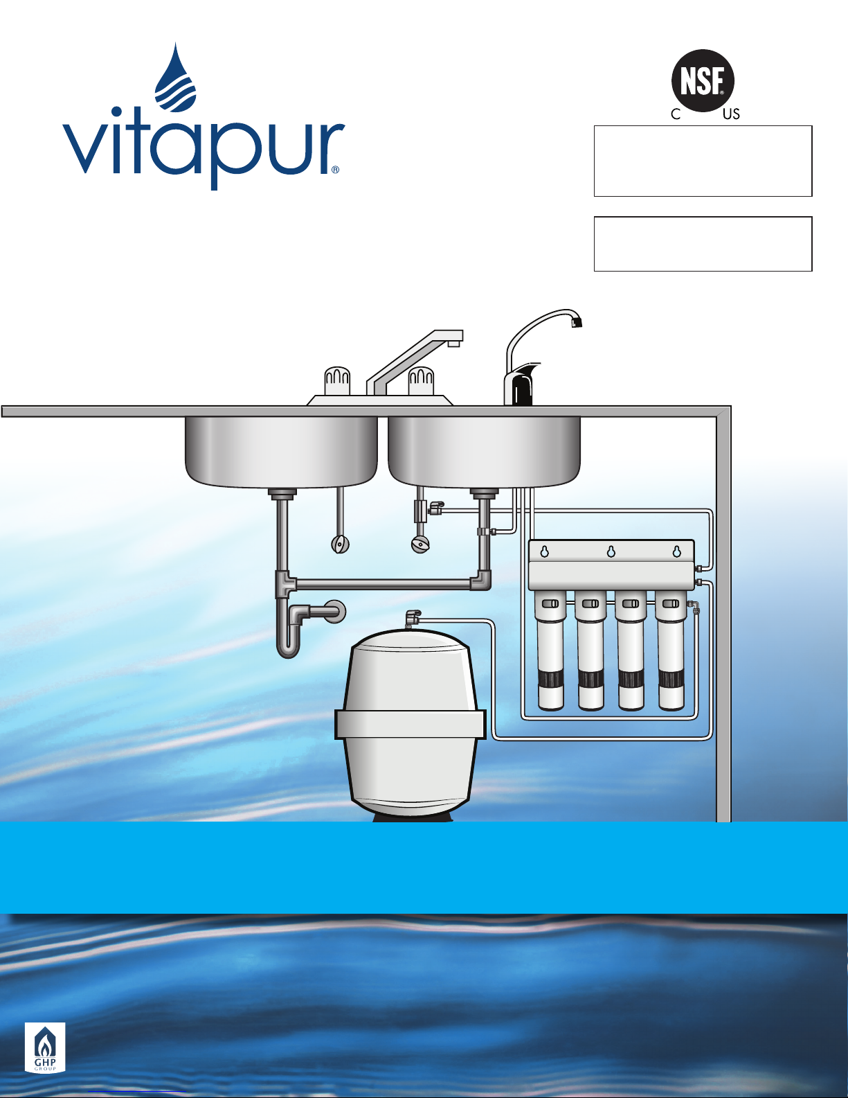
UNDER SINK
Reverse Osmosis Filtration Systems
The VRO-3Q and VRO-4Q have been tested
and certified by NSF International against
NSF/ANSI Standard 42, 58 and CSA B483.1
for reduction of the claims specified on the
performance data sheet
The VRO-5Q has been tested and certified by
NSF International against NSF/ANSI Standard
58 and CSA B483.1 for reduction of the claims
specified on the performance data sheet
VRO-3Q
VRO-4Q
VRO-5Q
Installation, Use & Care Guide
(Customer must read this manual thoroughly before installing the system)
CONSUMER: Retain this manual for future reference.
Questions, problems, missing parts? Before returning to your retailer, call our customer service department at:
1 (877)-447-4768. 8:30am-4:30pm CST, Mon - Fri or email us at [email protected]
GHP Group
USA: 6440 W. Howard Street, Niles, Illinois 60714
Canada: 271 Massey Road, Guelph, Ontario, N1K 1B2
2017-06-21
www.ghpgroupinc.com
Printed in China
Page 2

Table of Contents:
Safety Precautions ........................................................... 1
Conditions for Operation ................................................. 1
Package Contents ............................................................ 2
Tools Required for Installation ......................................... 2
System Layout and Components ............................... 3 - 5
Installation Instructions ............................................... 6 - 12
* Installing Quick Connect Filter ...................................... 6
* Un-installing Quick Connect Filter ................................. 6
* Tapping into Cold Water Line........................................ 7
* Drilling the Faucet Hole ............................................. 7 - 8
* Installing the Air-Gap Faucet ................................... 8 - 9
* Installing the Saddle Drain Clamp ......................... 9 - 10
* Mounting RO Unit Under Sink ...................................... 10
* Mounting the Ball Valve Onto Storage Tank ............. 11
* Connecting the Water Lines ....................................... 11
* Tubing Connection with Push-in Fitting ...................... 12
* Icemaker Hook-up (Optional) ..................................... 12
Start-up Instructions .................................................. 12 - 13
Periodic System Maintenance ............................... 13 - 14
RO membrane Replacement ....................................... 14
Post Carbon Filter Replacement (VRO-5Q only) ......... 15
Check Air Pressure in Storage Tank ............................... 15
Troubleshooting Guide for RO Systems ......................... 16
Performance Data.................................................... 17 -18
Replacement Parts List ............................................ 19 - 21
Limited Warranty ............................................................. 22
Safety Precautions:
• You must follow the guidelines to install this system. Check with your Province/State and
local public works department for plumbing and sanitation codes.
• If house water line pressure is over the maximum 100 psi (pounds per square inch), install a
pressure regulator in the water supply line before this system.
• System is for cold water use only and must be protected against freezing, which can
damage the unit and cause water leakage.
• Don’t use with the water that is microbiologically unsafe or of unknown quality without
adequate disinfection before or after the system. System certified for cyst reduction may
be used on disinfected water that may contain filterable cysts.
• Make sure the water supply conforms to the specification guidelines. If the water supply
conditions are unknown, consult your local municipal water company or health
department about the quality and the list of contaminants of the water in your area.
• CAUTION: When using the system for the first time or after replacing the membrane, the
system should be purged for 24 hours.
Conditions for Operation:
Supply Water Pressure Limits ........................................ 40 - 100 psi (276-689 kPa)
Supply Water Temperature Limits ............................... 40 - 113°F (4.4 -45°C)
Maximum Water pH Limits ........................................... 4-10
Maximum Total Dissolved Solids (TDS) ........................ 2,000 ppm
Maximum Water Hardness at 6.9 pH ......................... 10 gpg
Maximum Iron / Manganese / Hydrogen Sulde ..... 0.2/0/0 mg/L
Maximum Chlorine in Supply Water ........................... 2.0 ppm
Automatic shutoff control ........................................... Yes
1
Page 3
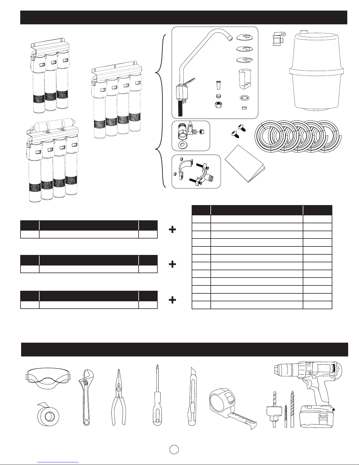
Package Contents:
A1
A3
VRO-3Q
VRO-4Q
A2
VRO-5Q
B.
C.
Accessories Kit
D.
G.
M.
E.
H. I. J. K. L.
F.
VRO-3Q
Part Description QTY
A1 Unit Assembly 1
VRO-4Q
Part Description QTY
A2 Unit Assembly 1
VRO-5Q
Part Description QTY
A3 Unit Assembly 1
Tools Required for Installation:
Part Description QTY
B Air-gap Faucet Set 1
C Inlet Valve Set 1
D Saddle Drain Clamp Set 1
E Tank Ball Valve 1
F Storage Tank 1
G Mounting Screw 2 or 3
H 6’ of 1/4” Blue Tubing 1
I 6’ of 1/4” Yellow Tubing 1
J 6’ of 1/4” Black Tubing 1
K 6’ of 1/4” Red Tubing 1
L 6’ of 3/8” Black Tubing 1
M Installation, Use & Care Guide 1
Safety Goggles
Teflon Tape
Adjustable
Wrench
Pliers Phillips
Screwdriver
Utility Knife
2
Measuring
Tape
Drill and Bits
(1/4”, 3/8” & 1” hole saw)
Page 4
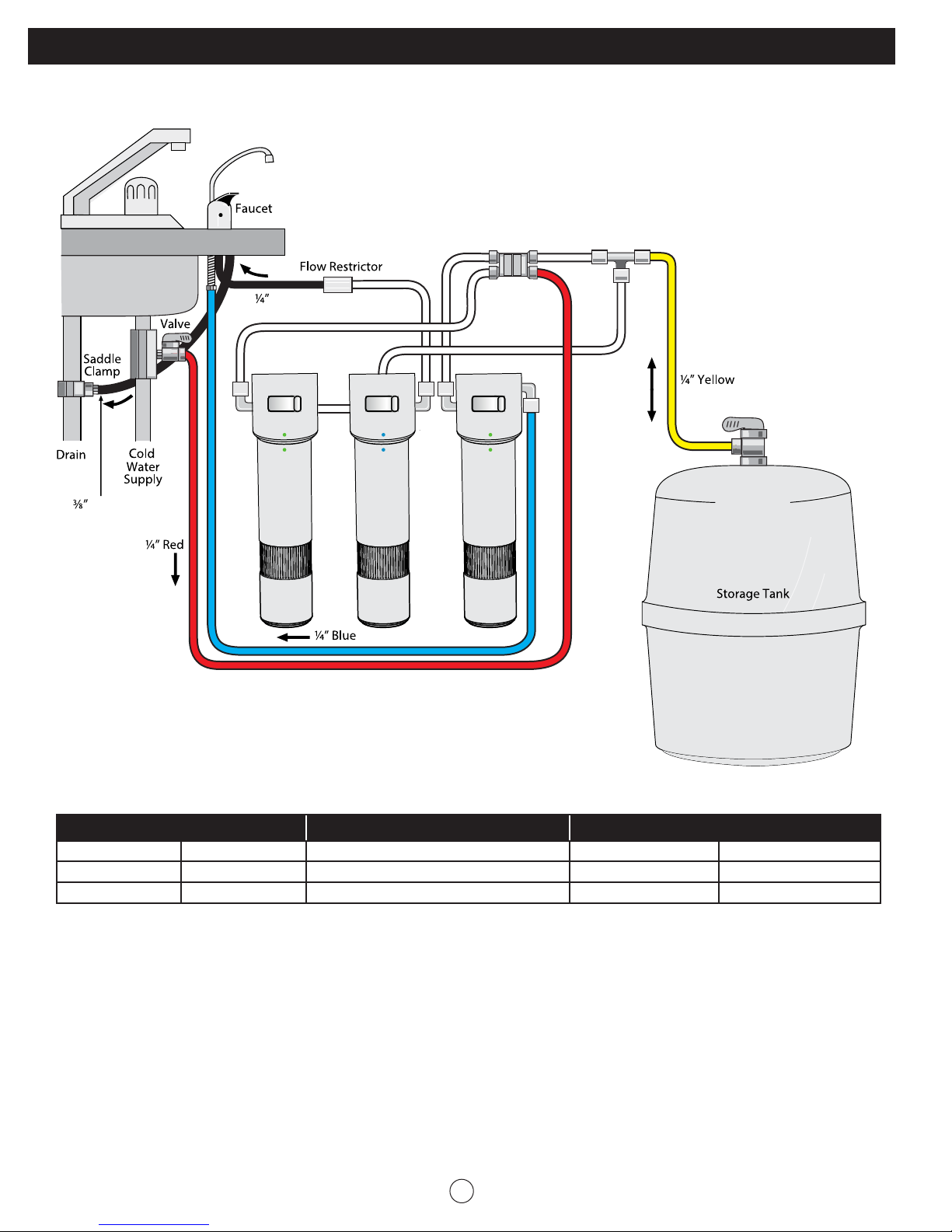
Reverse Osmosis System Layout and Components:
VRO-3Q Filtration Process:
Auto Shut-O Valve
Black
1st
Stage
Black
2nd
Stage
3rd
Stage
Replacement Parts
Filter Stage Part Number Description Service Life Filter Color Code
1st VRFQ-CTO Carbon Block Filter, 5 Micron 6 to 12 Months Green Dot
2nd VRFQ-RO TFC Membrane 50 GPD 24 to 36 Months Blue Dot
3rd VRFQ-CTO Carbon Block Filter, 5 Micron 6 to 12 Months Green Dot
3
Page 5
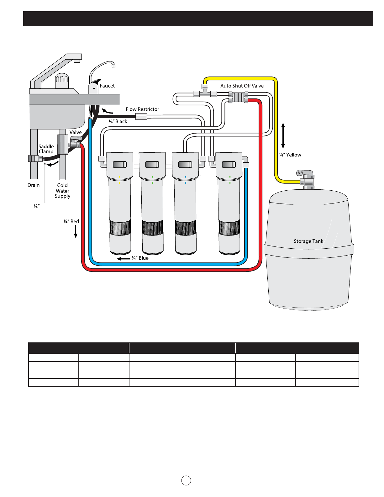
Reverse Osmosis System Layout and Components (continued):
VRO-4Q Filtration Process:
1st
Stage
Black
2nd
Stage
3rd
Stage
4th
Stage
Replacement Parts
Filter Stage Part Number Description Service Life Filter Color Code
1st VRFQ-PP PP Sediment Filter, 5 Micron 6 to 12 Months Yellow Dot
2nd VRFQ-CTO Carbon Block Filter, 5 Micron 6 to 12 Months Green Dot
3rd VRFQ-RO TFC Membrane, 50 GPD 24 to 36 Months Blue Dot
4th VRFQ-CTO Carbon Block Filter, 5 Micron 6 to 12 Months Green Dot
4
Page 6
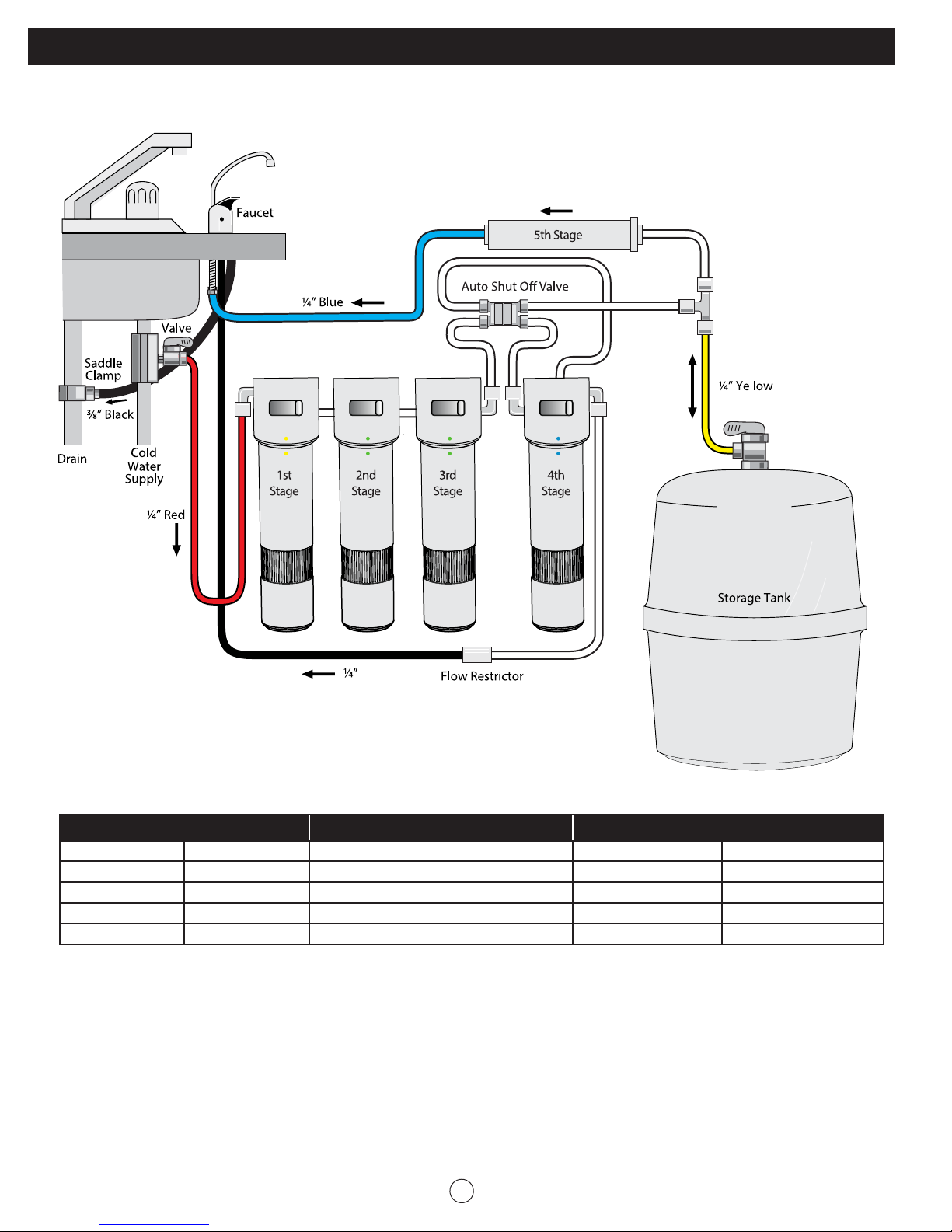
Reverse Osmosis System Layout and Components:
VRO-5Q Filtration Process:
Black
Replacement Parts
Filter Stage Part Number Description Service Life Filter Color Code
1st VRFQ-PP PP Sediment Filter, 5 Micron 6 to 12 Months Yellow Dot
2nd VRFQ-CTO Carbon Block Filter, 5 Micron 6 to 12 Months Green Dot
3rd VRFQ-CTO Carbon Block Filter, 5 Micron 6 to 12 Months Green Dot
4th VRFQ-RO TFC Membrane 50 GPD 24 to 36 Months Blue Dot
5th VRF-T33 T33 Inline Carbon Filter 6 to 12 Months N/A
5
Page 7
Installation Instructions:
All Vitapur RO Systems have been pre-assembled and tested at the factory, and don’t
need to dis-assemble. If you want to check or replace the filter(s). The following steps
need to be implemented:
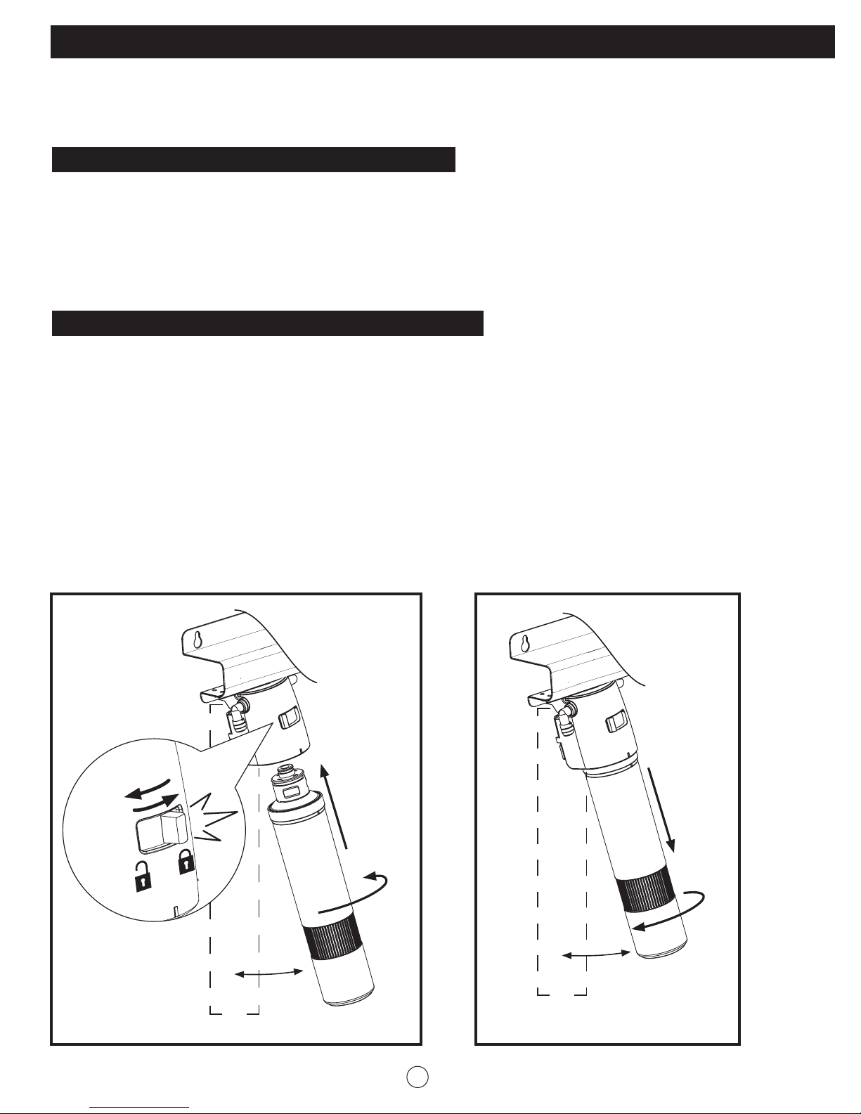
Installing the Quick Connect Filter (See Figure 1):
1. Unlock the Locking Tab by sliding it from the right to the left of the slot to ‘Unlock’
Position.
2. Lift the filter top section into the Head. Turn the filter about 1/4 turn in the direction as
shown in figure 1 until it stops.
3. Slide the Locking Tab from left to right of the slot to ‘Lock’ position.
Un-installing the Quick Connect Filter (See Figure 2):
1. Unlock the Locking Tab by sliding it from the right to the left of the slot to ‘Unlock’
Position.
2. Turn the filter in the direction as shown in figure 2 about 1/4 turn until it comes out of the
head.
NOTE: The filter head can be swung forward to assist in the filter installation.
CAUTION: Don’t attempt to turn the filter housing while in the ‘Lock’ position. It may
damage the system and cause leaks.
Figure 1. Figure 2.
45˚
1/4
1/4
45˚
6
Page 8
Installation Instructions (continued):
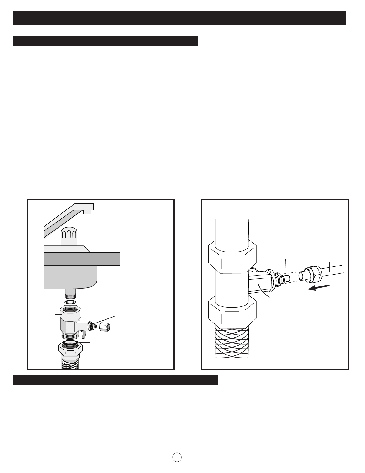
Tapping into Cold Water Line (See Figure 3 and 4):
CAUTION: The water supply to your unit MUST be from the COLD WATER LINE. Hot water will
severely damage your filtration system.
1. Turn off the cold water supply by turning off the shut off valve under the sink. If the cold
water line does not have a shut off valve under the sink, turn off the main water line in the
house. Place a tray or towel under the cold water line to catch the excess water.
2. Turn on the cold water faucet and allow all the water to drain from the line. On a single
handle faucet, the hot water may have to be turned off to prevent any hot water cross
over.
3. Loosen nut and separate cold water braided flex line from the kitchen cold water faucet
shank. Attach Inlet Valve to the faucet shank using the Rubber Washer. Reinstall the
flex line onto the inlet valve and tighten with an adjustable wrench. Use Teflon tape on
all threaded connection points.
4. Insert ¼” red tubing over the guide tube of the inlet valve. Tighten the compression nut
with an adjustable wrench.
Figure 3. Figure 4.
Guide Tube
1/4” Red
Tubing
Inlet
Valve
Inlet
Valve
Rubber
Washer
Guide Tube
Compression
Nut
Rubber
Washer
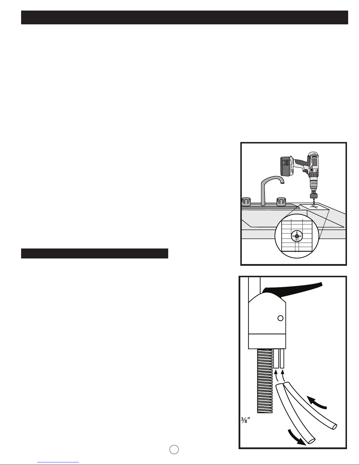
Drilling the Faucet Hole (See Figure 5 on the next page):
The drinking water faucet should be positioned with function, convenience and appearance in
mind. An adequate flat area is required to allow faucet to rest securely. Check the underside of
the location for interference. Most sinks have a pre-drilled 1½” or 1⁄” diameter holes designed
for spray hoses. The drinking water faucet may be installed using one of these holes, despite their
larger size. If the pre-drilled holes cannot be used, or are in an inconvenient location, it will be
necessary to drill a 1¼” hole in the sink or through the countertop next to the sink or the faucet.
7
Page 9
Installation Instructions (continued):
CAUTION: Do not drill through a counter top that is more than 1” thick.
CAUTION: Do not attempt to drill through a tiled, marble, granite or similar countertop. Consult
a plumber or the countertop manufacturer for advice or assistance
CAUTION: When drilling through a countertop make sure the area below the drilled area is free
of wiring and piping. Make certain that you have ample room to make the proper
connection to the bottom of the faucet.
CAUTION: Do not attempt to drill through an all-porcelain or porcelain-coated sink. For
applications on these types of sinks we recommend using the sprayer hole or
mounting the faucet through the countertop. Otherwise consult a plumber or
manufacturer for advice or assistance.
Figure 5.
1. Line the bottom of the sink with newspaper to prevent
shavings, parts, or tools from falling down the drain.
2. Place masking tape over the area to be drilled to help
prevent scratches if drill bit slips.
3. Mark point with a center punch. Use a ¼” drill bit to drill
a pilot hole
4. Use a 1¼” hole saw to enlarge the hole. Smooth rough
edges with a file.
Installing Air Gap Faucet (see figure 6):
1. Connect the ¼” black drain tube up to the ¼” fitting
on the air gap faucet.
2. Then connect the ⁄” black tubing to the ⁄” fitting on
the air gap faucet.
NOTE: Make sure the tubing is pushed all the way to the
end of the fitting
NOTE: The ⁄” black drain tube goes by gravity feed to
the saddle drain clamp connection. Make sure
there are no kinks, loops, or sharp bends in the
⁄” black tubing. Failure to make a straight line to
the drain may result in reject water leaking
through the air gap in the faucet onto the
countertop or below the faucet.
1¼”
¼”
Figure 6.
Air Gap
Window
¼” Black Drain
Line to Air Gap
Black Drain
Line from
Air Gap
8
Page 10
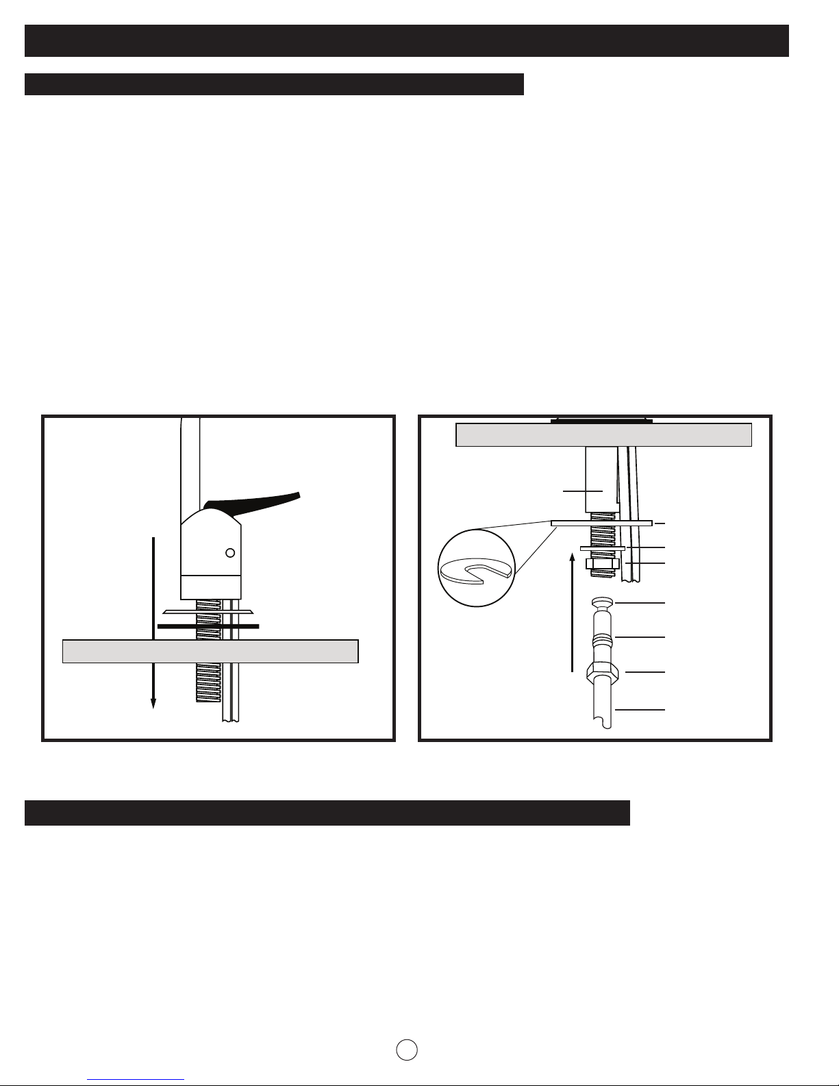
Installation Instructions (continued):
Installing the Air Gap Faucet Continued (see figure 7 and 8):
3. Loosen stem-nut on the faucet.
4. Slide Chrome Plate and Black Rubber Washer onto the faucet stem. The chrome plate,
rubber washer and faucet body are installed above sink or countertop.
5. Feed the ⁄” and ¼” black tubing through the pre-drilled hole in the sink/counter.
6. Place the faucet through the drilled faucet hole, then add Spacer, Securing Plate, Star
Lock Washer and Stem Nut.
7. Tighten stem nut firmly while aligning faucet in the desired location.
8. Gently slide Faucet Compression Nut down over the ¼” blue tubing, follow with Ferrule.
Then push Insert into the end of the tubing.
9. Firmly push the tubing into the stem of Faucet until it stops. Hand-screw the nut onto the
threads of the stem. Tighten with a wrench.
Figure 7. Figure 8.
Counter top
Spacer
Securing Plate
Lock Washer
Stem Nut
Insert
Ferrule
Faucet
Compression Nut
1/4” Blue Tubing
Counter top
Chrome Plate
Rubber Washer
Push into stem
3/4” deep
until it stops
Installing the Saddle Drain Clamp (see figure 9 and 10 on the next page):
1. Attach the drain clamp to the vertical section of the drain pipe, about 2 inches above the
drain trap.
2. Using the fittings hole of the drain clamp as a guide, drill a ¼” hole through one side of
the drainpipe.
CAUTION: Do not penetrate through the opposite side of the pipe.
3. Remove the drain clamp from the drainpipe and enlarge the hole with a ⁄” drill bit. Use
a file to remove rough edges from the drilled hole.
4. Cut the end of the ⁄” black tube at a 45˚ angle and insert it through the saddle drain
clamp quick connect fitting about 1” past the inside wall of the saddle clamp.
9
Page 11
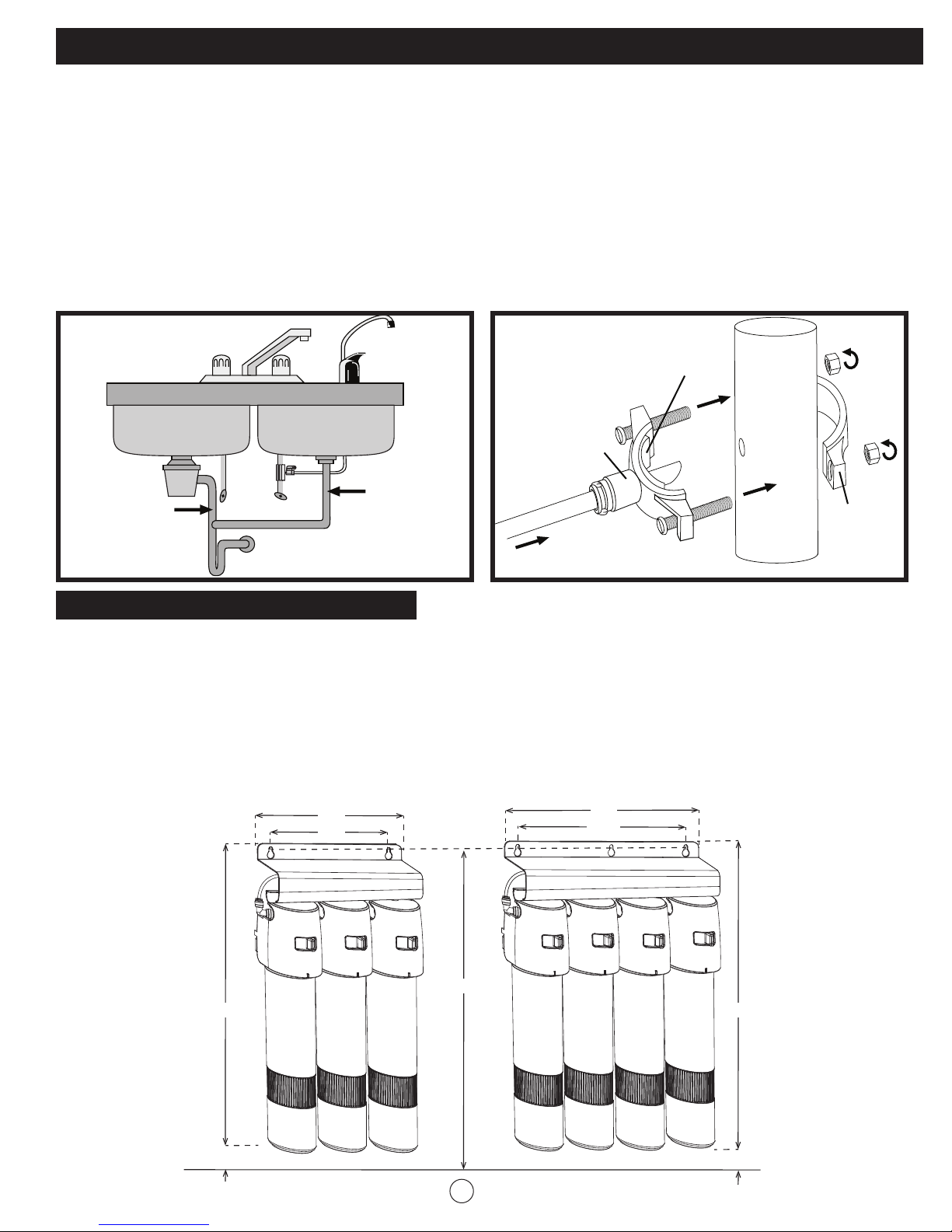
Installation Instructions (continued):
Mount Drain
Valve Here
Never
Mount
Here
5. Make sure the black rubber gasket is adhered to the inside wall of the clamp and place
the clamp assembly over the drain pipe. Insert ⁄” black tube into the drilled hole. Tighten
the clamp.
CAUTION: Do not overtighten the screws, it may crack the clamp.
CAUTION: The black 3/8” drain tube must be as SHORT and STRAIGHT as possible to the drain
saddle, making a downward slope from the faucet to the drain saddle to allow
for proper drainage. This is a gravity fed line and if there is any bend or dip in the
tubing, the rinse water will not flow into the drain properly. Water may back up and
come out the air gap hole in the faucet.
Figure 9. Figure 10.
Black Rubber
Gasket
Drain Clamp
Front Plate
Mount Drain
Never
Mount
Here
Valve Here
3
/8” Black Line
Drain Tubing
Drain Pipe
Drain Clamp
Back Plate
Mounting the RO Unit Under the Sink:
1. Position the RO unit on the back or right walls under the sink. Make sure to allow ample
space for the installation and plumbing connections. To change the filter cartridges, 1” of
clearance is required underneath the filter housings.
2. Install mounting screws at least 15 ¾” from cabinet floor. Leave 1/4” space between the
head of the screw and the wall to slip bracket onto the screws. Then tighten the screws to
secure the system.
System Dimensions: VRO-3Q VRO-4Q & VRO-5Q
11
14”
1
/
”
2
15 ¼”
15 ¼”
7
10”
7
/
”
8
3
/
15
”
4
1” Clearance
10
1” Clearance
Page 12
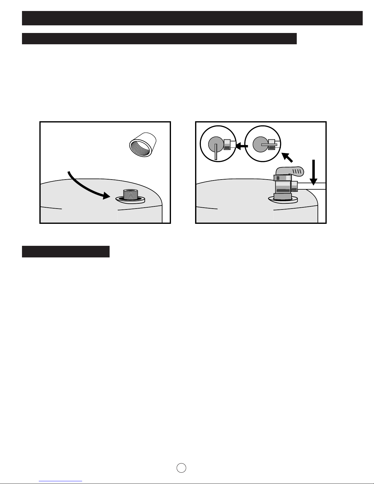
Installation Instructions (continued):
Mounting the Ball Valve Onto the Storage Tank (See figure 11 and 12):
1. Connect the Ball Valve to the water Storage Tank thread on the upper side of the tank.
Make sure the black rubber gasket sits flat. Tighten the valve but do not overtighten.
2. Connect the ¼” yellow tubing to the ball valve. Push the tubing in all the way to
make sure it is properly seated.
3. Turn the ball valve off.
Figure 11. Figure 12.
1/4” Yellow
Tubing
Rubber Gasket
Remove
Protective
Cap
Closed
Open
Ball Valve
Storage
Tank
Storage
Tank
Connecting the Tubes
CAUTION: Before cutting the supplied tubing measure the distance between the components.
All tubing is colour-coded for ease of installation.
¼” Black - Connects the waste water from the RO membrane to the Air Gap faucet intake line.
¼” Red - Connects the inlet valve of the cold water supply to the inlet of the system.
¼” Yellow - Connects the RO membrane to the storage tank.
¼” Blue - Connects the outlet of the system to the faucet.
3/8” Black - Connects the faucet to the drain saddle clamp.
Note: Reference the diagram on page 3, 4 or 5 for colour and connection point on the RO System.
Each connection point has coloured plugs to match the colour of the tubing that connects
at that point. The plugs must be removed before installing the tubing.
Quick connect fittings are used throughout the system. To insure an optimal seal, tubing
should be cut with the end square. An angled cut or distortion of the tubing will not
provide a proper seal and may cause leaks.
To remove the plugs and install the tubing, please see “Tubing Connection with Push-in Fittings”.
11
Page 13
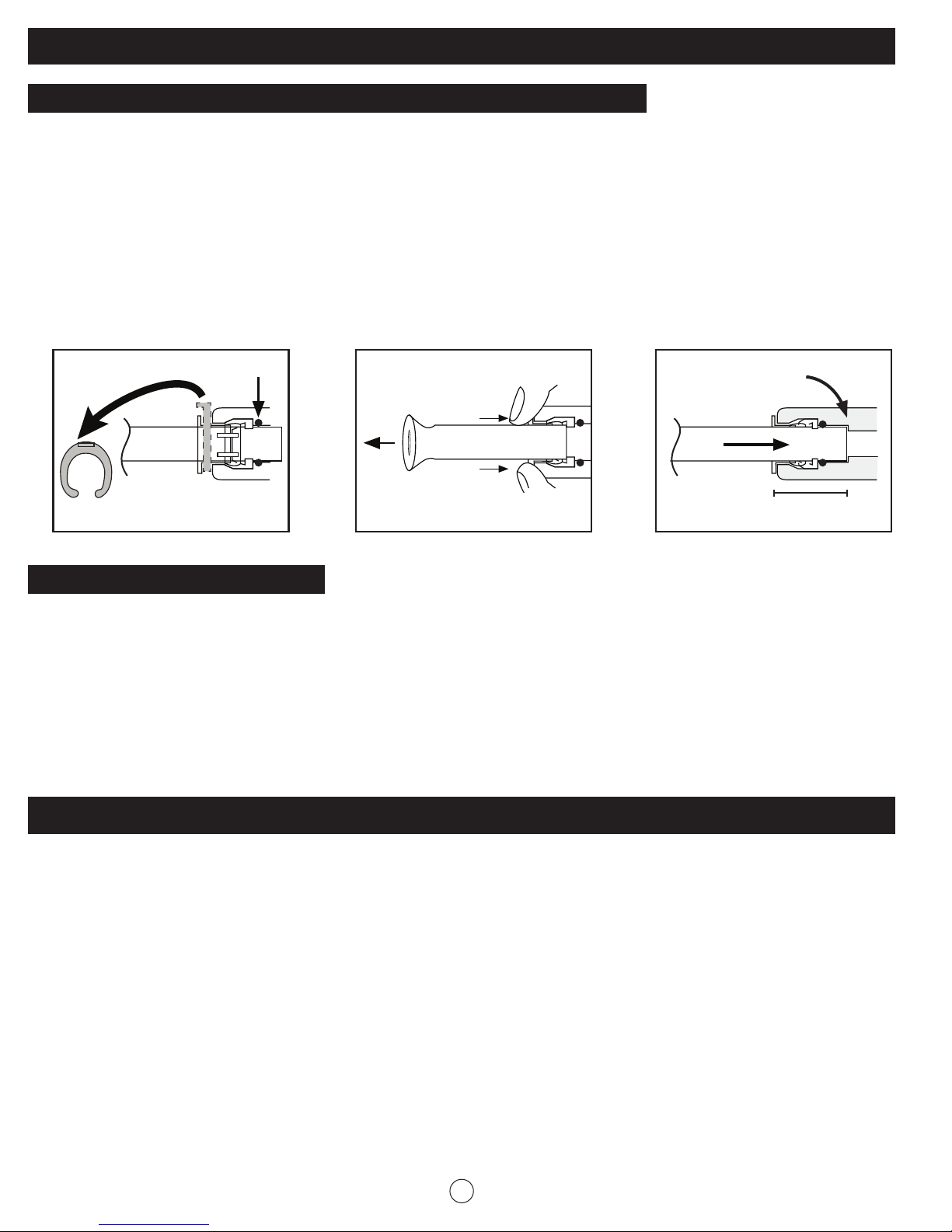
Installation Instructions (continued):
Tubing Connection with Push-in Fittings (See Figure 14, 15 and 16):
1. Take off the blue horseshoe clip from collet.
2. Pull out and discard the protect plug by pushing the collet inward and holding with
fingers.
3. Insert Tubing into the collet. Full engagement is 11/16” length of the tubing into the
fitting for 1/4” tubing, and 3/4” length for 3/8” tubing.
NOTE: Ensure tubing is pushed all the way to backstop.
4. Put blue horseshoe clip back on collet.
Figure 14. Figure 15. Figure 16.
BackstopO-Ring
Collet
Horseshoe
Clip
Full engagement length
Icemaker Hook-Up (optional):
Install 1/4” polypropylene plastic tubing if your refrigerator is within 25 ft. of your RO unit.
Do not use copper tubing since an objectionable taste can result in the ice cubes. If the
refrigerator is over 25 ft from the RO Unit it is recommended to use 3/8” tubing. Install a tee
in the blue tubing between the outlet of the system and the faucet. It is recommended to
install a ball valve in the line to your ice maker to allow pressure to increase sufficiently in the
storage tank for the ice maker solenoid valve to operate properly. Leave the ball valve in the
closed position until the tank is full after the start up procedure is completed.
Start-up Instructions:
NOTE: If you have connected your RO system to a refrigerator/ice maker, make sure the ice
maker is off (do not allow water to flow to the ice maker until flush is complete and the
tank has been allowed to fill completely. Connection from the RO to the icemaker
system should have an inline valve installed before the icemaker so it can easily be
closed to prevent water flowing to the ice maker during start up and periodic
maintenance. Your RO tank must be allowed to fill up fully for the ice maker system to
work properly.
1. Turn Inlet Valve and Storage Tank Ball Valve both in open position.
2. Ensure RO faucet is closed.
3. Slowly open the cold water supply valve that you closed at the beginning of this installation.
12
Page 14
Start-up Instructions (continued):
4. Water pressure will start to build in the RO system in about 2 hours. Carefully inspect all
fittings and connections. Check for leaks and fix if any are found.
5. Open RO faucet and let water flow through the system for a 24 hour period. Water will flow
heavily until the Storage Tank becomes empty, and then it will be a slow drip for the
balance of 24 hours.
6. Close RO faucet after 24 hour purge is complete.
7. RO system is ready for use.
NOTE: you will not have filtered water immediately. It will take 1-2 hours to completely fill the storage
tank to create liberal flow from the RO faucet.
Periodic System Maintenance:
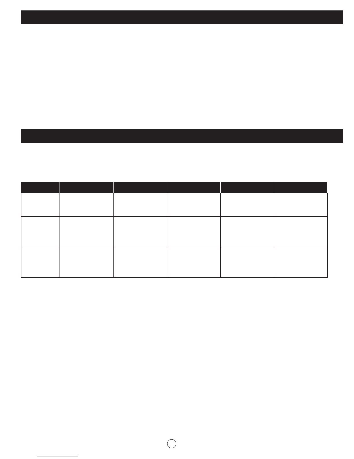
Depending on which model was purchased the chart below will assist with replacement of
filters. The replacement filter can be obtained online at www.ghpgroupinc.com or at the retail
store where the system was purchased.
Model # Stage 1 Stage 2 Stage 3 Stage 4 Stage 5
VRO-3Q
VRO-4Q
VRO-5Q
5 micron Carbon
block Part#
VRFQ-CTO
5 micron PP
Sediment Filter
Part#
VRFQ-CTO
5 micron PP
Sediment Filter
Part#
VRFQ-CTO
RO membrane
Part #
VRFQ-RO
5 micron Carbon
block Part#
VRFQ-CTO
5 micron Carbon
block Part#
VRFQ-CTO
5 micron Carbon
block Part#
VRFQ-CTO
RO membrane
Part #
VRFQ-RO
5 micron Carbon
block Part#
VRFQ-CTO
n/a n/a
5 micron Carbon
block Part#
VRFQ-CTO
RO membrane
Part #
VRFQ-RO
n/a
Inline Carbon
Filter
Part#
VRF-T33
The prefilter and postfilter have a life expectancy between 6 to 12 months, depending on
the incoming water conditions and the amount of the water the system has used. You must
periodically replace the filters. This will protect the RO membrane from being destroyed by
Chlorine and also prevent the filters from plugging with sediment.
NOTE: Place a tray or towel under the RO system to catch any water drips before uninstalling the filter
sumps.
For Model VRO-3Q:
1. Refer “Un-install Quick Connect Filter” on page 6, to remove 1st stage of filter (left one in
front of the system).
2. Then, remove 3rd stage of the filter (right one in front of the system).
3. Discard the filters in a proper manner.
4. Refer “Install Quick Connect Filter” on page 6, to install the new filters in the reverse order,
install the 3rd-stage of the filter first, then the 1st stage of the filter.
5. Go to step 7.
13
Page 15

Periodic System Maintenance (continued):
For Model VRO-4Q:
1. Refer “Un-install Quick Connect Filter” on page 6, to remove 1st stage of filter (left one in
front of the system).
2. Then, remove 2nd and 4th stage of filters.
3. Discard the filters in a proper manner.
4. Refer “Install Quick Connect Filter” on page 6, to install the new filters in the reverse order,
install the 4th stage of the filter first, then 2nd stage and the last is 1st stage.
5. Go to step 7.
For Model VRO-5Q:
1. Refer “Un-install Quick Connect Filter” on page 6, to remove the 1st stage of filter (left one in
front of the system).
2. Then, remove 2nd and 3rd stage of filters.
3. Refer “Post Carbon Filter Replacement” on page 15, to remove the inline post carbon filter.
4. Discard the filters in a proper manner.
5. Refer “Install Quick Connect Filter” on page 6, to install the new filters in the reverse order:
install the inline post filter first, then, 3rd and 2nd stages, and the last is 1st stage.
6. Go to step 7.
7. Turn off the ball valve of the storage tank, and turn the RO faucet open by lifting the handle
upward. The water begins to trickle out (it will come out very slow). Allow to drip for 15
minutes.
8. Then Close the RO faucet, open the ball valve of the storage tank. The RO system is ready
for use!
RO Membrane Replacement:
The membrane has a life expectancy between 24 to 36 months, depending on the incoming
water conditions and the amount the RO system is used. The membrane is critical for effective
reduction of claims. The product water should be tested periodically to verify that the system is
performing satisfactory.
Remove the membrane:
1. Refer to “Un-install Quick Connect Filter” on page 6, to remove RO membrane housing.
2. Discard the housing in a proper manner.
Install the membrane:
1. Refer to “Install Quick Connect Filter” on page 6, to install a new RO membrane housing.
2. Follow “Start-up Instructions” on page 13 to flashing the system before using.
14
Page 16
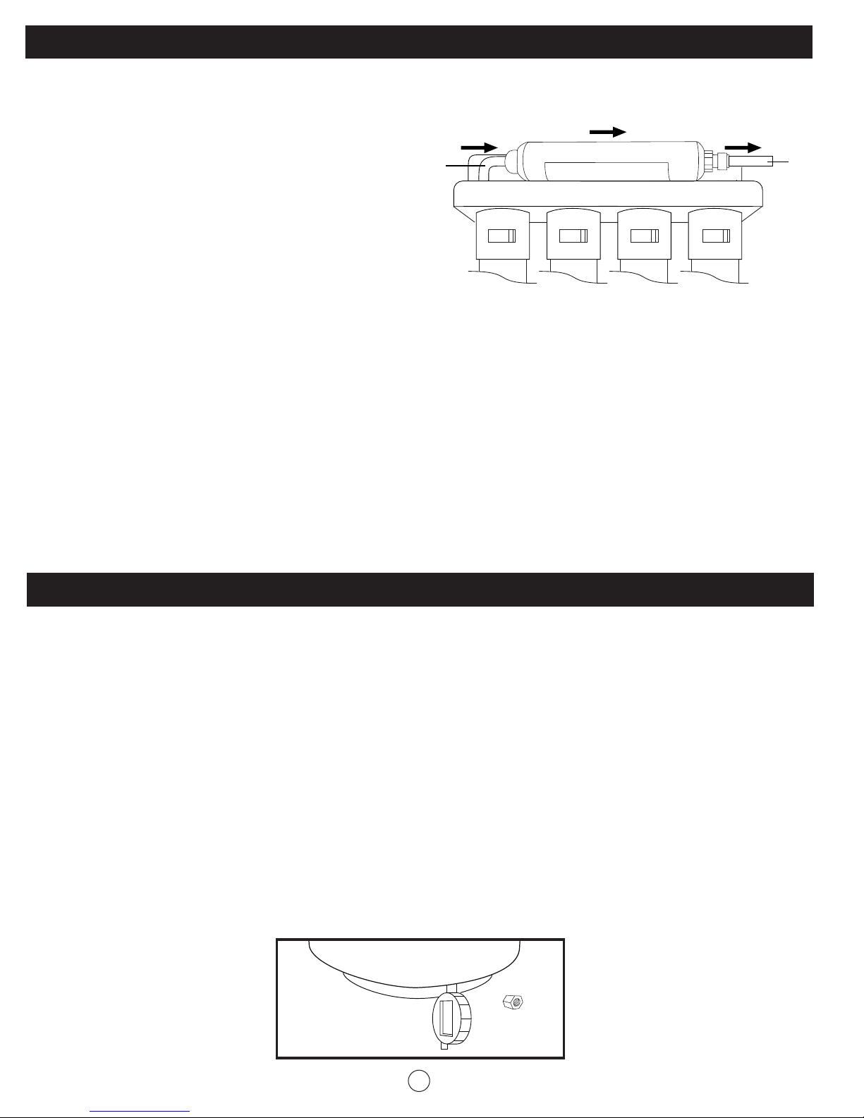
Post Carbon Filter Replacement (VRO-5Q only):
The inline post carbon filter has a life expectancy between 6 to 12 months. The inline post carbon filter is
an effective filter in removing any post taste and odor.
1. Turn off the inlet valve.
2. Close the ball valve of the storage tank.
1/4” White
Tubing
Water
Inlet
Flow Direction
Inline Post Carbon Filter
Water
Outlet
1/4” Blue
Tubing
3. Open the RO faucet to release the
Filter Housing Bracket
pressure in RO system.
Removing the Expired Inline Post Carbon Filter:
1. Remove the blue horseshoe securing the ¼” blue tubing in the quick connect on the old inline post
carbon filter. Then disconnect the blue tubing by pushing in the collet and pulling out the blue tubing.
2. Repeat the same procedure to remove ¼” white tubing from other end of the inline post carbon filter.
3. Pull off the filter from the plastic mounting brackets that are attached to the metal bracket.
Installing the New Inline Post Carbon Filter:
1. Remove the outer packaging from the new Inline Post Carbon Filter. Place the filter onto the inline filter
mounting brackets as illustrated on the previous page.
2. Connect the ¼” blue tubing back into the outlet of the filter. Replace the blue horseshoe to secure the
tubing.
3. Connect the ¼” white tubing into the inlet of the filter. Replace the blue horseshoe to secure the tubing.
4. Follow steps 7 - 8 of “Periodic System Maintenance” on page 14.
Check Air Pressure in the Tank:
Important: Check air pressure only when the tank is empty of water!
Check air pressure in the storage tank when you notice a decrease in available water from the RO
system. Air can be added with a bicycle pump using the valve that is located on the bottom of the tank
covered by a black cap.
1. Turn off the incoming water supply to the RO by turning the inlet valve counter clockwise until it
stops.
2. Open the RO Faucet and allow the water to drain from the tank until it is completely empty.
Tip: When water from the RO faucet slows to a trickle, with the faucet still in the open position, you
may add air to the tank to purge any left over water, this will ensure that the tank is completely
empty.
3. Once all the water in the tank is purged, check the air pressure using an air pressure gauge, it should
read between 5 to 7 psi. (Digital air pressure gauge is recommended). Pump the air into the tank to
meet the spec if necessary.
4. Open the tank ball valve and inlet valve, when the storage tank is full you can enjoy the RO water.
Black CapAir Pressure Gauge
15
Page 17
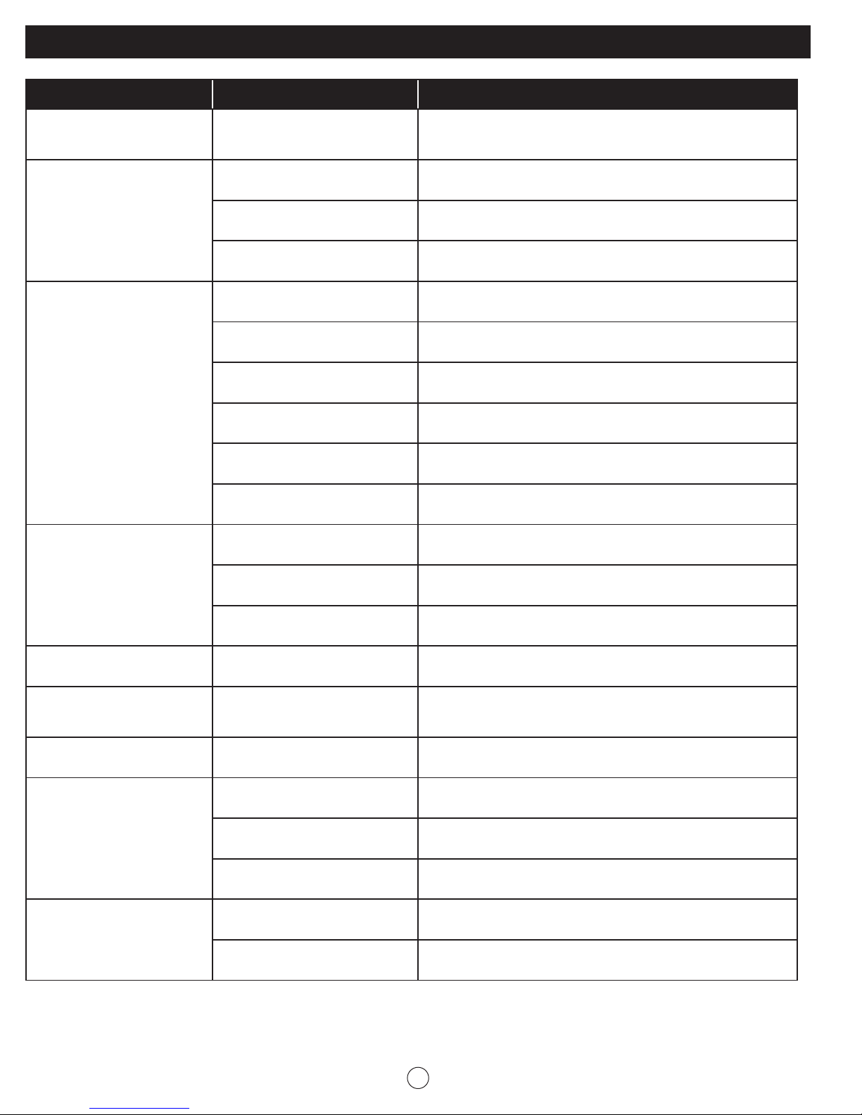
Troubleshooting Guide for the RO Systems:
Problem Possible Cause Solution
It’s a normal occurrence during initial start-up of the system.
Milky coloured water Air in system
Air gap of faucet Inherent sound with an air-gap faucet
This milky colour will disappear during normal use within 1 to
2 weeks
Noise from faucet
Slow Water production
Offensive water taste or
smell
Location of drain saddle Relocate the drain to a horizontal location
Restriction in drain line
Low water pressure
System just start up Normally it takes up to 2 hours to fill the storage tank
Low air pressure in storage tank
Crimp in tubing Check tubing straighten or repair as necessary
Clogged pre-filters Replace pre-filters
Fouled membrane Replace the membrane
Post carbon filter is depleted Replace post filter
Fouled membrane Replace the membrane
Sanitizer not flushed out
Clear blockage that is sometimes caused by debris from
garbage disposal unit or dishwasher
The systems require min 40 psi incoming water pressure. A
booster pump maybe needed in low water area
Add air pressure to the tank. The pressure should be 5 to 7
psi when the tank is empty
Drain storage tank and refill it. Repeat to discard 3 tanks of
water
No drain water Clogged flow restrictor Replace the flow restrictor
Water leak from faucet air
gap hole
Water leak at thread fittings Fitting not tightened Wrap Teflon tape and tighten fittings as necessary
Water leak at quick connect
fittings
Water leak at sump
connection
3/8” black tubing plugged,
restricted or incorrectly
connected to drain point
Tubing not cut square Cut the tubing end square
Tubing not pushed in all the
way
Tubing nicked or outer surface
finish not smooth
Sump not in right position Turn the sump into the lock position
O-ring missed or damaged Checked the O-rings and replace
Eliminate restriction or plug. Check the drain line is routed
properly, not clogged or crimped
Push the tubing in all the way
Pull tubing out of connection, cut off problem area and
reinsert in connection.
For further operating, installation, or maintenance assistance call GHP Group Inc. customer service department at
1 (877)-477-4768 Mon. - Fri. 8:30 a.m. – 4:30 p.m. CST or email us at [email protected]
16
Page 18

Performance Data:
Reverse Osmosis Drinking Water System
Model: VRO-3Q, VRO-4Q and VRO-5Q
The system must be installed and operated in accordance with manufacturer’s recommended
procedures and guidelines. Failure to follow the instructions may result in the leakage,
malfunction and will void warranty.
Read this performance date and compare the capabilities of this unit with your actual water
treatment needs. It’s recommended that you have your supply water tested to determine your
actual water treatment needs.
Arsenic Fact Sheet
This system has been tested for the treatment of water containing pentavalent arsenic (also
known as As(V), As(+5) or Arsenate) at concentration of 0.30 mg/L or less. The systems reduce
pentavalent arsenic, but may not reduce other forms of arsenic. These systems are also to
be used on the water supplies containing a detectable free chlorine residual or own water
supplies that have been demonstrated to contain only pentavalent arsenic. Treatment with
Chloramine (combined chlorine) is not sufficient to ensure complete conversion of trivalent
arsenic to pentavalent arsenic.
Arsenic is a naturally occurring contaminant found in many ground waters. There are two forms
of arsenic: Pentavalent Arsenic [also called as As(V), As(+5) or Arsenate] and Trivalent Arsenic
[As (III), As (+3) and Arsenite]. Although both forms are potentially harmful to human health,
trivalent arsenic is considered more harmful than pentavalent arsenic.
Arsenic in water has no color, taste or odor. It must be measured by a lab test. Public water
utilities must have their water tested for arsenic. You can get the results from your water utility. If
you have your own well, you can have the water tested. The local health department or state
environmental health agency can provide a list of certified labs.
RO systems do not remove trivalent arsenic from water very well. RO systems are very effective
at reducing pentavalent arsenic. If you have free chlorine residual in contact with your water
supply for at least one minute, the trivalent arsenic will be converted to pentavalent arsenic
and reduced by RO systems. Other water treatment chemicals, such as: ozone and potassium
permanganate, will also change trivalent arsenic to pentavalent arsenic. A combined chlorine
residual (also called chloramine) may not convert all the trivalent arsenic. If you get your
water from a public water utility, contact the utility to find out if free chlorine or combined
chlorine is used in the water system.
The system requires regular replacement of all filters to maintain proper operation. Depending
on usage and influent water quality, the sediment and carbon filters should be changed at
least annually and the RO membrane should be replaced very 3 years. Variation of chlorine,
sediment or TSD levels may affect replacement frequency.
17
Page 19
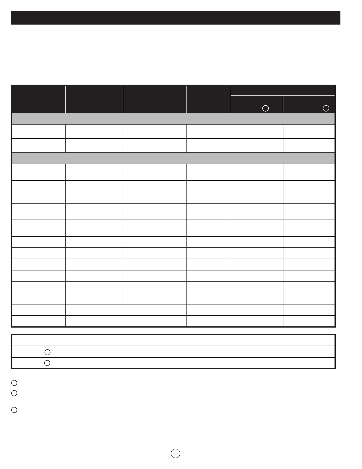
Performance Data Sheet:
The VRO-3Q and the VRO-4Q have been tested and certified by NSF International according to NSF/ANSI
42 and 58 and the VRO-5Q has been tested and certified by NSF International according to NSF/ANSI 58
for the reduction of the substances listed below.
The concentration of the indicated substances in water entering the system was reduced to a
concentration less than or equal to the permissible limit for water leaving the system, as specified in NSF/
ANSI 58. While testing was performed under standard laboratory conditions, actual performance may vary.
Performance Claims for VRO-3Q, VRO-4Q and VRO-5Q
Average influent
Substance
challenge
concentration
NSF Standard 42
Aesthetic Chlorine
(VRO-3Q & 4Q post filter only)
Particulate Class III
(VRO-3Q & 4Q post filter only)
NSF Standard 58
Arsenic
(pentavalent)
Barium 10.0 mg/L ± 10% 2.0 mg/L
Cadmium 0.03 mg/L ± 10% 0.005 mg/L
Chromium
(Hexavalent)
Chromium
(Trivalent)
Copper 3.0 mg/L ± 10% 1.3 mg/L
Fluoride 8.0 mg/L ± 10% 1.5 mg/L
2.0 mg/L ± 10% ≥ 50%
10,000/mL ≥ 85%
0.30 mg/L ± 10% 0.010 mg/L
0.30 mg/L ± 10% 0.10 mg/L
0.30 mg/L ± 10% 0.10 mg/L
Maximum
allowable product
water level
Percent
reduction
requirement
Tested Performance
Product water
level
0.007 mg/L 99.2%
0.43 mg/L 97.6%
0.0014 mg/L 98.1%
0.009 mg/L 98.5%
0.010 mg/L 96.7%
0.1 mg/L 98.7%
0.4 mg/L 95.7%
1
Percent
Reduction
91.8%
99.9%
1
Lead 0.15 mg/L ± 10% 0.010 mg/L
Radium 226/228 25 pCi/L ± 10% 5 pCi/L
Selenium 0.10 mg/L ± 10% 0.05 mg/L
TDS 750 ± 40 mg/L 187 mg/L
Cyst ≥ 50,000 /mL 99.95%
Turbidity 11 ± 1 NTU 0.5 NTU
Daily Production Rate: 20.40 gpd
Efficiency:
Recovery: 3 27.81%
1
Tested by NSF International according to NSF/ANSI standard 42 and 58.
2
Efficiency rating means the percentage of the influent water to the system that is available to the user as
2
14.97%
0.005 mg/L 96.6%
5 pCi/L 80%
0.002 mg/L 97.9%
25 mg/L 96.7%
< 0.1 NTU > 99.1%
reverse osmosis treated water under operating conditions that appropriate typical daily usage.
3
Recovery rating means the percentage of the influent water to the membrane portion of the system that is
available to the user as reverse osmosis treated water when the system is operated without a storage tank or
when the storage tank is bypassed.
Manufactured and warranted by:
GHP Group
USA: 6440 W. Howard Street, Niles, Illinois 60714
Canada: 271 Massey Road, Guelph, Ontario, N1K 1B2
18
99.99%
Page 20
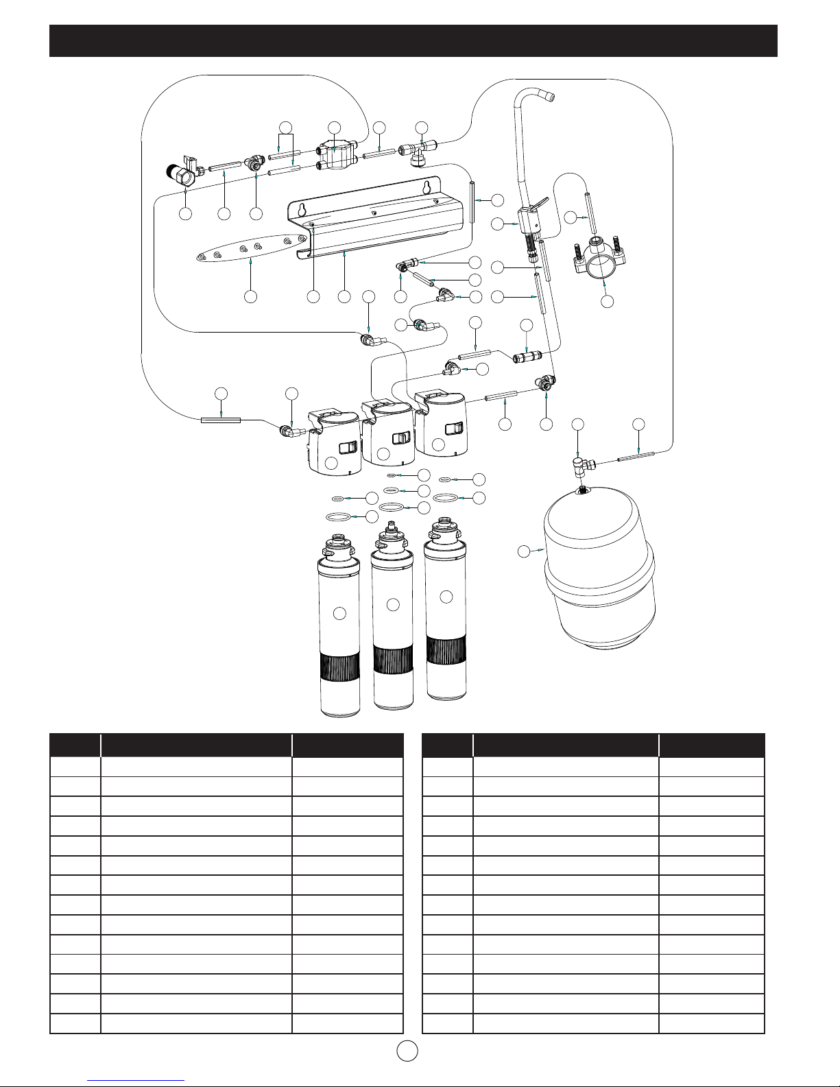
Replacement Parts List:
11
18
10
12
14
15
11
13
11
11
11
19
18
9
11
11
11
11
9
23
24
21
21
27
28
17
VRO-3Q
12 2827
26
1125
22
12
10
13
12
12
5
23
7
12
2324621
10
10
14
15
16
13
18
19
16
8
10
12
10
15
16
9
12
11
1
4
2 3
17
S/N Description Part #
1 Storage Tank YY.VRO3Q-1
2 Tank Ball Valve YY.VRO3Q-2
3 6’ of 1/4" Yellow Tubing YY.VRO3Q-3
4 Saddle Drain Clamp Set YY.VRO3Q-4
5 6’ of 3/8” Black Tubing YY.VRO3Q-5
6 Air-gap Faucet Set YY.VRO3Q-6
7 6’ of 1/4” Black Tubing YY.VRO3Q-7
8 6’ of 1/4” Blue Tubing YY.VRO3Q-8
9 Flow Restrictor, 300 mL YY.VRO3Q-9
10 1/4" QC Elbow, Plug-in YY.VRO3Q-10
11 1/4" QC Elbow YY.VRO3Q-11
12 6’ of 1/4" White Tubing YY.VRO3Q-12
13 Carbon Filter Head YY.VRO3Q-13
14 RO membrane Head YY.VRO3Q-14
20
17
S/N Description Part #
15 Small O-ring, Filter Housing YY.VRO3Q-15
16 Big O-ring, Filter Housing YY.VRO3Q-16
17 Carbon Block Filter VRFQ-CTO
18 Small O-ring, RO Housing YY.VRO3Q-18
19 Medium O-ring, RO Housing YY.VRO3Q-19
20 RO Membrane VRFQ-RO
21 Metal Bracket YY.VRO3Q-21
22 Mounting Screw, Filter Head YY.VRO3Q-22
23 1/4" QC One-way Elbow YY.VRO3Q-23
24 Mounting Screw, Bracket YY.VRO3Q-24
25 Inlet Valve Set YY.VRO3Q-25
26 6’ of 1/4” Red Tubing YY.VRO3Q-26
27 Auto Shutoff Valve YY.VRO3Q-27
28 1/4" QC Tee YY.VRO3Q-28
19
Page 21
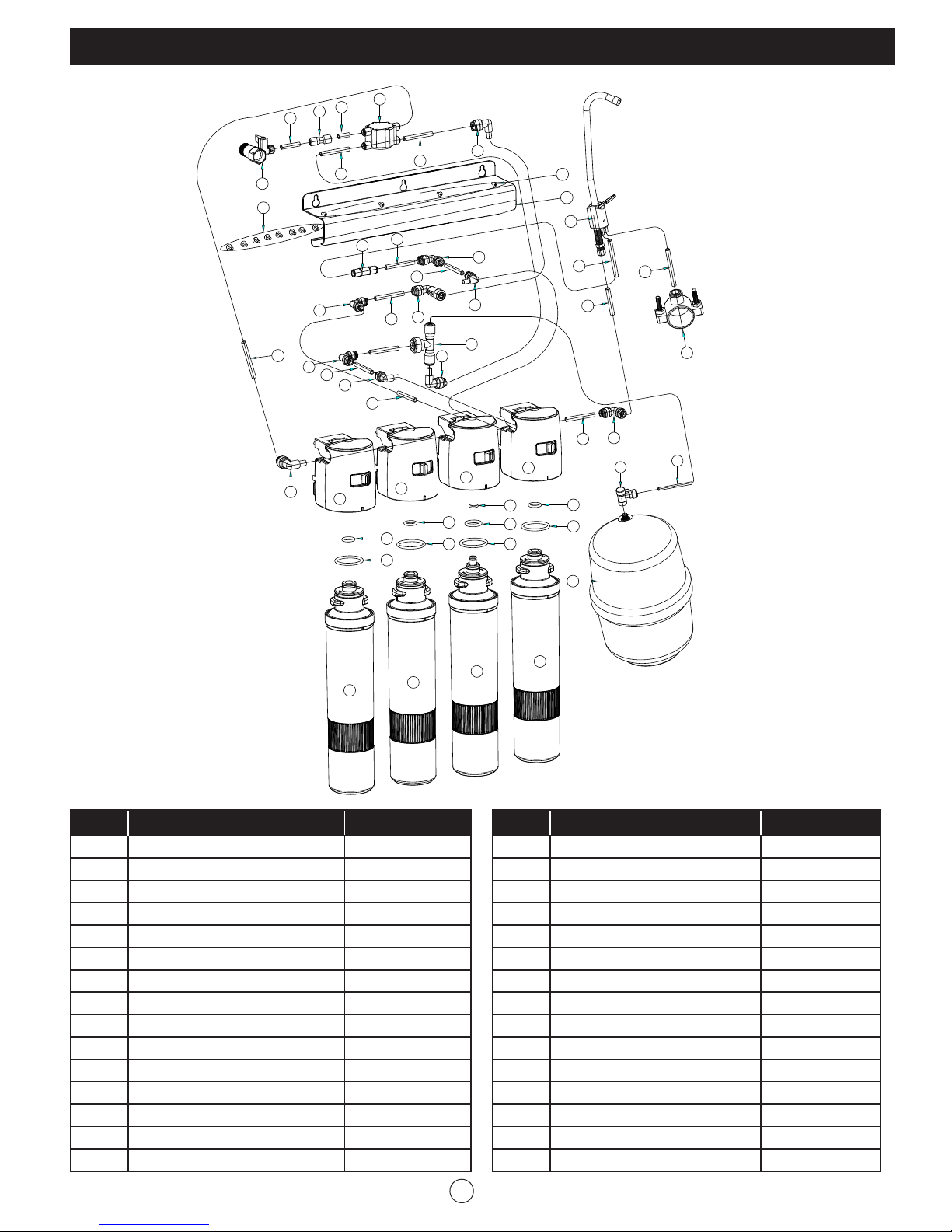
Replacement Parts List:
11
11
21
21
27
26
25
12 16 11
11 1215
11
16
30
31
20
19
18
VRO-4Q
10
11
12
13
14
15
11
9
11
17
18
18
11
9
11
21
11
11
11
19
11
21
23
24
9
30
16
6
18
9
20
9
22
23
24
21
25
26
24
7
8
11
23
24
1
5
4
18
2
3
27
28
S/N Description Part #
1 Storage Tank YY.VRO4Q-1
2 Tank Ball Valve YY.VRO4Q-2
3 6’ of 1/4" Yellow Tubing YY.VRO4Q-3
4 Saddle Drain Clamp Set YY.VRO4Q-4
5 6’ of 3/8” Black Tubing YY.VRO4Q-5
6 Air-gap Faucet Set YY.VRO4Q-6
7 6’ of 1/4” Black Tubing YY.VRO4Q-7
8 6’ of 1/4” Blue Tubing YY.VRO4Q-8
9 1/4" QC Elbow, Plug-in YY.VRO4Q-9
10 Auto Shutoff Valve YY.VRO4Q-10
11 6’ of 1/4" White Tubing YY.VRO4Q-11
12 1/4" QC Straight YY.VRO4Q-12
13 6’ of 1/4” Red Tubing YY.VRO4Q-13
14 Inlet Valve Set YY.VRO4Q-14
15 Mounting Screw, Filter Head YY.VRO4Q-15
29
28
S/N Description Part #
16 Metal Bracket YY.VRO4Q-16
17 Flow Restrictor, 300 mL YY.VRO4Q-17
18 1/4" QC Elbow YY.VRO4Q-18
19 1/4" QC One-way Elbow YY.VRO4Q-19
20 1/4” QC Tee YY.VRO4Q-20
21 Carbon/PP Filter Head YY.VRO4Q-21
22 RO membrane Head YY.VRO4Q-22
23 Small O-ring, Filter Housing YY.VRO4Q-23
24 Big O-ring, Filter Housing YY.VRO4Q-24
25 Small O-ring, RO Housing YY.VRO4Q-25
26 Medium O-ring, RO Housing YY.VRO4Q-26
27 Sediment (PP) Filter VRFQ-PP
28 Carbon Block Filter VRFQ-CTO
29 RO Membrane VRFQ-RO
30 Mounting Screw, Bracket YY.VRO4Q-30
20
Page 22
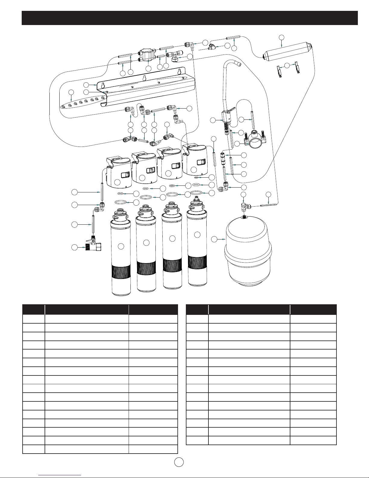
Replacement Parts List:
VRO-5Q
12
13
11
11
14
11
11
19
18
20
12
12 16 11
11 1215
21
11
16
21
26
25
12
21
26
25
22
26
25
12
11
6
11
23
24
25
5
7
4
17
8
11
16
2
10
9
3
30
31
27
28
S/N Description Part #
1 Storage Tank YY.VRO5Q-1
2 Tank Ball Valve YY.VRO5Q-2
3 6’ of 1/4" Yellow Tubing YY.VRO5Q-3
4 Saddle Drain Clamp Set YY.VRO5Q-4
5 6’ of 3/8” Black Tubing YY.VRO5Q-5
6 Air-gap Faucet Set YY.VRO5Q-6
7 6’ of 1/4” Black Tubing YY.VRO5Q-7
8 6’ of 1/4” Blue Tubing YY.VRO5Q-8
9 C-shape Holder YY.VRO5Q-9
10 Post Filter T33 VRF-T33
11 6’ of 1/4" White Tubing YY.VRO5Q-11
12 1/4" QC Elbow, Plug-in YY.VRO5Q-12
13 1/4” QC Tee YY.VRO5Q-13
14 Auto Shutoff Valve YY.VRO5Q-14
15 1/4" QC One-way Elbow YY.VRO5Q-15
16 1/4" QC Elbow YY.VRO5Q-16
28
29
1
S/N Description Part #
17 Flow Restrictor, 300 mL YY.VRO5Q-17
18 Mounting Screw, Bracket YY.VRO5Q-18
19 Metal Bracket YY.VRO5Q-19
20 Mounting Screw, Filter Head YY.VRO5Q-20
21 Carbon/PP Filter Head YY.VRO5Q-21
22 RO membrane Head YY.VRO5Q-22
23 Small O-ring, RO Housing YY.VRO5Q-23
24 Medium O-ring, RO Housing YY.VRO5Q-24
25 Big O-ring, Filter Housing YY.VRO5Q-25
26 Small O-ring, Filter Housing YY.VRO5Q-26
27 Sediment (PP) Filter VRFQ-PP
28 Carbon Block Filter VRFQ-CTO
29 RO Membrane VRFQ-RO
30 6’ of 1/4” Red Tubing YY.VRO5Q-30
31 Inlet Valve Set YY.VRO5Q-31
21
Page 23
Warranty:
Limited Warranty:
This limited warranty is extended to the original retail purchaser of this filtration system and warrants against any defect in
material and workmanship for a period of one (1) year from the date of retail sale. GHP Group, Inc., at its option, will either
provide replacement parts or replace the unit, when properly returned to the retailer where purchased or one of our service
centers as directed by GHP Group, Inc., within one (1) year of retail purchase. (Shipping costs, labour costs, etc. are the
responsibility of the purchaser.)
Duties of the Owner:
This filtration system must be installed and operated in accordance with the written instructions furnished with this system.
This warranty shall not excuse the owner from properly maintaining this unit in accordance with the instructions. A bill of sale,
canceled check or payment record must be kept to verify purchase date and establish warranty period. Original carton
should be kept in case of warranty return of the unit.
What is Not Covered?
1. Damage caused by misuse, installation or use contrary to the owner’s manual and safety guidelines.
2. Use of this product where water is microbiologically unsafe or of unknown quality.
3. Damage of caused by a lack of normal maintenance and cleaning.
4. Use of non-OEM parts or accessories.
5. Damage caused in transit. Freight charges on warranty parts or products to and from the factory shall be the responsibility
of the owner.
THIS LIMITED WARRANTY IS GIVEN TO THE PURCHASER IN LIEU OF ALL OTHER WARRANTIES, EXPRESSED OR IMPLIED, INCLUDING
BUT NOT LIMITED TO THE WARRANTIES OF MERCHANTABILITY OF FITNESS FOR A PARTICULAR PURPOSE. THE REMEDY PROVIDED IN
THIS WARRANTY IS EXCLUSIVE AND IS GRANTED IN LIEU OF ALL OTHER REMEDIES. IN NO EVENT WILL GHP GROUP. INC. BE LIABLE
FOR INCIDENTAL OR CONSEQUENTIAL DAMAGES.
Some states/provinces do not allow limitations or how long an implied warranty lasts, so the above limitation may not apply
to you. Some states/provinces do not allow the exclusion or limitation of incidental or consequential damages so the above
limitation or exclusion may not apply to you.
Claims Handles as Follows:
1. Contact your retailer and explain the problem
2. If the retailer is unable to resolve the problem, contact our Customer Service Dept. detailing the system model,
the problem, and proof of date of purchase.
3. A representative will contact you. DO NOT RETURN THE UNIT TO GHP GROUP, INC. unless instructed by our
Representative, or written authorization.
This warranty gives you specific legal rights and you may also have other rights that vary from state/province to state/province.
TO REGISTER THIS WARRANTY PLEASE FILL OUT THIS CARD COMPLETELY AND MAIL WITHIN FOURTEEN (14) DAYS
FROM THE DATE OF PURCHASE OR REGISTER ON-LINE AT www.ghpgroupinc.com
NAME: ______________________________________ PHONE: ( ) __________________ EMAIL: __________________________________
ADDRESS: _________________________________ CITY: ______________________________ STATE/PROV: __________ ZIP: ____________
MODEL: ____________________ SERIAL #: _______________________________________ DATE PURCHASED: __________________
DEALER PURCHASED FROM: ____________________________________________ TYPE OF STORE: __________________________
CITY & STATE WHERE PURCHASED: ______________________________________________ PRICE PAID: _______________________
Please Take a Minute To Give Us Your Answers To The Following Questions.
All Responses Are Used Solely For Market Research And Are Held In Strict Confidence.
Who primarily decided this purchase? ¨ Male ¨ Female ¨ 18-24 ¨ 25-39 ¨ 40-59 ¨ 60 and over
Purpose of Purchase? _______________________________________________________________________________________________
Do you own any other filtration systems? ¨ Yes ¨ No If yes, type____________________________brand_____________________
How do you intend to use your new system? ¨ Replace existing ¨ New location ¨ Other
How did you become aware of this system? ¨ In-Store Display ¨ Newspaper Ad ¨ Magazine Ad ¨ Friend/Relative
¨ TV Commercial ¨ Store Salesperson ¨ Other ___________________________
What made you select this system? ¨ Style ¨ Reduction claims ¨ Price ¨ Package ¨ Brand ¨ Other _____________
Would you recommend this system to a friend? ¨ Yes ¨ No
Please give us your comments:________________________________________________________________________________________
THANK YOU FOR COMPLETING THIS FORM!
Information will be held confidential.
22
 Loading...