

VitalWell VW801, VW802, VW804, VW803 User Manual

VViittaallWWeellll EElleeccttrroonniiccss PPttee LLttdd..
Tel: +86-0756-3867295
Block D3, #415/416, Southern Software Park, TangJia,, ZZhhuuHHaaii,, CChhiinnaa 551199008800
vital-well.com
VW801
VW802
VW803
VW804
Serial-WiFi Modem User Manual (Rev. 1.0)
Overview of Characteristics
² Support IEEE802.11b/g/n Wireless Standards
² Built-in USB-Serial Bridge Chip (Silabs CP2102)
² Support AT commands sending from serial port
² Support connections over AT commands
² Support transparent mode (serial<->wifi)
² Support STA /AP /AP+STA Modes
² Support WPS functions
² Support automatically DDNS connections
² Based on High performance MCU
² High sensitivity, Long range
² Support Multi-TCP Link (5 Channel) Application
² Variable Interfaces: USB(Virtual COM), RS485, 232TTL, RS232
² Onboard PCB Antenna

VViittaallWWeellll EElleeccttrroonniiccss PPttee LLttdd..
Tel: +86-0756-3867295
Block D3, #415/416, Southern Software Park, TangJia,, ZZhhuuHHaaii,, CChhiinnaa 551199008800
vital-well.com
TABLE OF CONTENTS
1. PRODUCT OVERVIEW .............................................................................................................. 1
1.1. General Description .......................................................................................................... 1
1.1.1. Device Features ...................................................................................................... 1
1.1.2. Specifications .......................................................................................................... 2
1.1.3. Key Application ....................................................................................................... 2
1.2. Hardware Introduction ....................................................................................................... 3
1.2.1. Pins Definition ......................................................................................................... 3
2. FUNCTIONAL DESCRIPTION .................................................................................................... 5
2.1. Wireless Networking ......................................................................................................... 5
2.1.1. Basic Wireless Network Based On AP (Infrastructure) ............................................ 5
2.1.2. Wireless Network Based On AP+STA ..................................................................... 5
2.2. Operate Mode : Transparent Transmission Mode ............................................................. 6
2.3. UART Frame Scheme ....................................................................................................... 7
2.3.1. UART Free-Frame .................................................................................................. 7
2.3.2. UART Auto-Frame .................................................................................................. 7
2.4. Encryption ......................................................................................................................... 8
2.5. Parameters Configuration ................................................................................................. 8
2.6. SOCKET B Function ......................................................................................................... 8
2.7. Multi-TCP Link Connection ................................................................................................ 9
3. OPERATION GUIDELINE ......................................................................................................... 10
3.1. VW801/ VW802/ VW803/ VW804 Usage Introduction ..................................................... 10
3.1.1. Software Tools ...................................................................................................... 10
3.1.2. Network Connection .............................................................................................. 10
3.1.3. Default Parameter Setting ..................................................................................... 11
3.1.4. Modem Test .......................................................................................................... 11
3.2. Typical Application Examples .......................................................................................... 14
3.2.1. Wireless Control Application .................................................................................. 14
3.2.2. Remote Management Application.......................................................................... 14
3.2.3. Transparent Serial Port Application ....................................................................... 14
4. AT+INSTRUCTION INTRODUCTION ....................................................................................... 16
4.1. Configuration Mode ......................................................................................................... 16
4.1.1. Switch to Configuration Mode ................................................................................ 16
4.2. AT+Instruction Set Overview ........................................................................................... 17
4.2.1. Instruction Syntax Format...................................................................................... 18
4.2.2. AT+Instruction Set................................................................................................. 19
APPENDIX A: HTTP PROTOCOL TRANSFER ............................................................................. 37
A.1. HTTP AT command ........................................................................................................ 37
A.2. HTTP Example ............................................................................................................... 39
APPENDIX B: Doument History .................................................................................................. 40

VW801, VW802, VW803, VW804 Serial-WiFi Modem User Manual
Vitalwell Electronics (Zhuhai) Pte. Ltd. www.vital-well.com email: Vitalwell@vital-well.com 1
1. PRODUCT OVERVIEW
1.1. General Description
VW801/2/3/4 low-power embedded Serial-WiFi modem series provides a way to use the popular
serial interface (RS485, USB virtual COM, 232TTL, RS232,) to transfer data over Wi-Fi wireless
networking. The module integrates hardware MAC, baseband chip, RF transceiver unit, and a
power amplifier; the embedded firmware supports flexible Wi-Fi protocols, TCP / IP protocol stack,
as well as kinds of networking configuration.
VW801 modem built-in a USB-Serial bridge chip, an integrated 801.11 b/g/n Wi-Fi subsystems.
Through VW801, a large number of traditional serial interface based applications can easily
access/control Wi-Fi enabled networks/devices.
VW80x uses the industry's lowest-power embedded structure, targeting embedded wifi data/ control
applications, for the instance, for example in: smart home, wifi lighting, wifi socket, smart grid,
handheld devices, personal medical, industrial control, IP sensors, etc. VW801 series modems do a
professional optimization on these applications.
VW80x series integrate all wifi features in a compact size measure only 72mm x 24mm x 9mm.
Using a convenient solid USB connector, allowing the user plug into the user end equipment easily.
Module is equipped with built-in PCB antenna, no external antenna needs.
VW80x series modem looks clean and beautiful, suitable for the various embedded I.O.T
applications.
VW80x series include these 4 models modem (interface different):
² VW801: USB VCOM
² VW802: 232TTL interface
² VW803: RS232C interface
² VW804: RS485 interface
1.1.1. Device Features
l Support IEEE802.11b/g/n Wireless Standards
l Built-in USB-Serial Bridge Chip (Silabs CP2102, VW801)
l Various interface: RS485, 232TTL, RS232C, USB VCOM
l Support AT commands sending from serial port
l Support connections on AT commands
l Support transparent mode (serial<->wifi)

VW801, VW802, VW803, VW804 Serial-WiFi Modem User Manual
Vitalwell Electronics (Zhuhai) Pte. Ltd. www.vital-well.com email: Vitalwell@vital-well.com 2
l Support STA /AP /AP+STA Modes
l Support WPS functions
l Support automatically DDNS connections
l Based on High performance MCU
l High sensitivity, Long range
l Support Multi-TCP Link (5 Channel) Application
l Onboard PCB Antenna
l Compact surface mount module 72mm x 24mm x 9mm
1.1.2. Specifications
Table 1 VW801 Module Technical Specifications
Class Item Parameters
Certification FCC/CE
Wireless standard 802.11 b/g/n
Frequency range 2.412GHz-2.484GHz
Transmit Power
802.11b: +16 +/-2dBm (@11Mbps)
Wireless 802.11g: +14 +/-2dBm (@54Mbps)
Parameters
802.11n: +13 +/-2dBm (@HT20, MCS7)
Receiver Sensitivity
802.11b: -93 dBm (@11Mbps ,CCK)
802.11g: -85 dBm (@54Mbps, OFDM)
802.11n: -82 dBm (@HT20, MCS7)
Data Interface USB/ RS485/ 232TTL
Operating Voltage 4~5.5V
Operating Current
Peak [Continuous TX]: ~200mA
Hardware Normal [WiFi ON/OFF, DTIM=100ms]:
Parameters
Average. ~12mA, Peak: 200mA
Standby : <200uA(Reserved)
Operating Temp. -40℃- 85℃
Storage Temp. -45℃- 125℃
Dimensions and Size 72mm×24mm×9mm
Network Type STA /AP/STA+AP
Software Security Mechanisms WEP/WPA-PSK/WPA2-PSK
Parameters Encryption WEP64/WEP128/TKIP/AES
Network Protocol IPv4, TCP/UDP/FTP/HTTP
User Configuration AT+instruction set
1.1.3. Key Application
l Smart lighting, smart socket
l Home automation
VW801, VW802, VW803, VW804 Serial-WiFi Modem User Manual
Vitalwell Electronics (Zhuhai) Pte. Ltd. www.vital-well.com email: Vitalwell@vital-well.com 3
l IP sensors
l Embedded I.O.T add-on WIFI
l Remote equipment monitoring
l Asset tracking and telemetry
l Security
l Industrial sensors and controls
l Medical devices
l etc
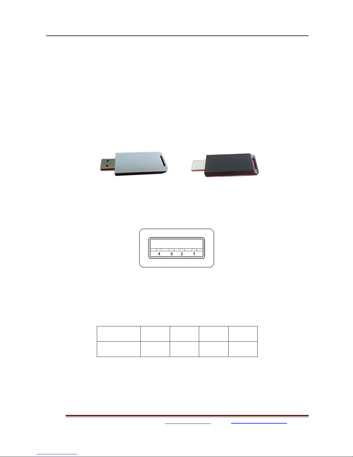
1.2. Hardware Introduction
Figure 1. VW801/ VW802/ VW803/ VW804 View
1.2.1. Pins Definition
Figure 2. VW801 Pins Map
(USB A type, front view)
Table 2 VW801(USB VCOM) Pins Definition
Pin 1 2 3 4
Signal VCC D- D+ GND

VW801, VW802, VW803, VW804 Serial-WiFi Modem User Manual
Vitalwell Electronics (Zhuhai) Pte. Ltd. www.vital-well.com email: Vitalwell@vital-well.com 4
Table 3 VW802(232TTL) Pins Definition
Pin 1 2 3 4
Signal VCC RXD TXD GND
Table 4 VW803(232C) Pins Definition
Pin 1 2 3 4
Signal VCC RXD TXD GND
Table 5 VW804(RS485) Pins Definition
Pin 1 2 3 4
Signal VCC B A GND
VW801, VW802, VW803, VW804 Serial-WiFi Modem User Manual
Vitalwell Electronics (Zhuhai) Pte. Ltd. www.vital-well.com email: Vitalwell@vital-well.com 5
2. FUNCTIONAL DESCRIPTION
Notes for symbols:
AP: that is the wireless Access Point, the founder of a wireless network and the centre of the
network nodes. The wireless router we use at home or in office may be an AP.
STA: short for Station, each terminal connects to a wireless network (such as laptops, PDA and
other networking devices) can be called with a STA device.
2.1. Wireless Networking
VW801 series modem can be configured as both wireless STA and AP base on network type. Logically
there are two interfaces in VW801: STA or AP. When VW801 operates as AP, other STA equipments
are able to connect to VW801 modem directly. Wireless networking with VW801 series modem is very
flexible.
In the following diagram, we’ll use VW801 as example.
2.1.1. Basic Wireless Network Based On AP (Infrastructure)
Infrastructure: it’s also called basic network. It is built on AP and many STAs which join in.
The characters of network of this type are that AP is the centre, and all communication between
STAs is transmitted through the AP. The following figure shows this type of networking.
Figure 3. VW801 Basic Wireless Network Structure
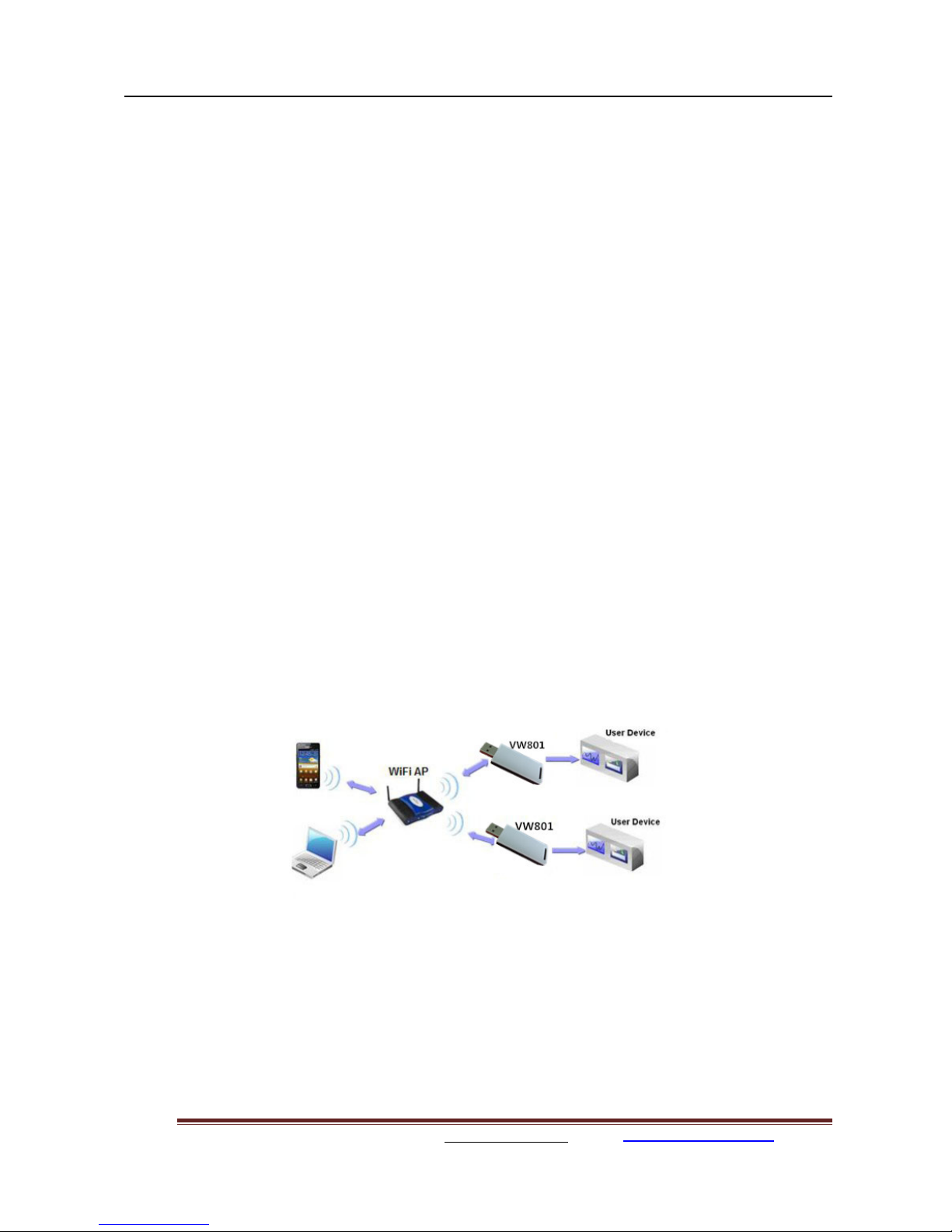
2.1.2. Wireless Network Based On AP+STA
VW801 series modem support AP+STA network mode, means VW801 support one AP interface and
one STA interface at the same time, as following figure,
VW801, VW802, VW803, VW804 Serial-WiFi Modem User Manual
Vitalwell Electronics (Zhuhai) Pte. Ltd. www.vital-well.com email: Vitalwell@vital-well.com 6
Figure 4. VW801 AP+STA Network Structure
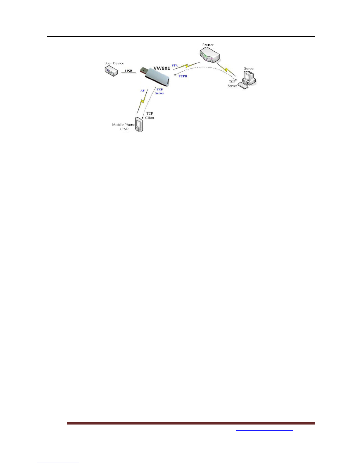
When VW801 modem enables AP+STA function, Modem’s STA interface can connect with router and
then connect to TCP server in the network. At the same time, module’s AP interface is also active and
allow phone/PAD to connect it through TCPB, then phone/PAD can control / communicate with VW801
and other devices within the network.
The advantage of AP+STA mode is:
Users can easily control user device through Phone/PAD, and no need changing the original network
setting.
Users can easily setting modem’s parameters through WiFi when module works as STA mode.
2.2. Operate Mode : Transparent Transmission Mode
VW801 modem support serial interface transparent transmission mode.
In this mode, VW801 functions as a serial<->WIFI bridge, gives user a wireless serial port over WIFI.
Users just only configure the necessary parameters. After power on, the modem will automatically
connect to the default wireless network / server.
When in this mode, the modem's serial port always work in the transparent transmission mode, users
can think it as a virtual wireless serial cable, and can send and receive data as usual like using a simple
wired serial cable. In other words, the original serial cable on devices is directly replaced with the
modem; user devices can then be easily converted to wireless enabled devices without any changes.
The transparent transmission mode will fully compatible with user’s original software platform and
reduce the software development effort for integrate wireless data transmission.
The parameters which need to configure include:
Wireless Network Parameters
Wireless Network Name (SSID)
Security Mode
Encryption Key

VW801, VW802, VW803, VW804 Serial-WiFi Modem User Manual
Vitalwell Electronics (Zhuhai) Pte. Ltd. www.vital-well.com email: Vitalwell@vital-well.com 7
TCP/UDP Linking Parameters
Protocol Type
Link Type (Server or Client)
Target Port ID Number
Target Port IP Address
Serial Port Parameters
Baud Rate
Data Bit
Parity (Check) Bit
Stop Bit
Flow Control
2.3. UART Frame Scheme
2.3.1. UART Free-Frame
VW801 support UART free-frame function. If user select open this function, module will check the
intervals between any two bytes when receiving UART data. If this interval time exceeds defined value
(50ms default), VW801 will think it as the end of one frame and transfer this free-frame to WiFi port,
or VW801 will receive UART data until 1000 bytes, then transfer the 1000 bytes frame to WiFi port.
VW801’s default interval time setting is 50ms. User can also set this interval some faster (10ms) through
AT command. But user have to consider if user MCU / applications can send all UART data continuously
within 10ms interval time requirement ,or the UART data may be divide as fragment chocks.
Through AT command: AT+UARTTE=fast/normal, user can select the interval time: fast (10ms) and
normal (50ms).
2.3.2. UART Auto-Frame
VW801 support UART auto-frame function. If user select open this function and setting auto-frame
trigger length and auto-frame trigger time parameters, then module will auto framing the data which
received from UART port and transmitting to the network as pre-defined data structure.
Auto-frame trigger length: The fixed data length that module used to transmitting to the network.
Auto-frame trigger time: After the trigger time, if UART port received data can’t reach auto-frame
trigger length, then module will transmitting available data to the network and bypass the auto-frame
trigger length condition.
Detailed UART auto-frame function can refer to AT+instruction set “UARTF/UARTFT/UARTFL”
introduction.
VW801, VW802, VW803, VW804 Serial-WiFi Modem User Manual
Vitalwell Electronics (Zhuhai) Pte. Ltd. www.vital-well.com email: Vitalwell@vital-well.com 8
2.4. Encryption
Encryption is a method of scrambling a message that makes it unreadable to unwanted parties, adding
a degree of secure communications. There are different protocols for providing encryption, and the
VW801 modem supports following:
WEP
WPA -PSK/TKIP
WPA -PSK/AES
WPA2 -PSK/TKIP
WPA2 -PSK/AES
2.5. Parameters Configuration
VW801 modem supports AT + instruction set mode parameter configuration. AT+instruction set
configuration means user configure parameters through serial interface command.
Refer to “AT+instruction set” chapter for more detail.
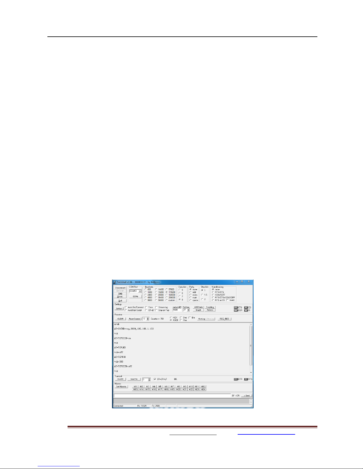
2.6. SOCKET B Function
VW801 support double socket communication, the socket B function is disabled by default.
After the modem is ready, send command “AT+SOCKB” to set the connection parameter, send
command “AT+TCPDISB=on” to try to connect with TCP server. Send command “AT+TCPDISB=off”
to close connection. Send command “AT+TCPLKB” to inquire TCP connection.
Figure 5. Socket B function demo
VW801, VW802, VW803, VW804 Serial-WiFi Modem User Manual
Vitalwell Electronics (Zhuhai) Pte. Ltd. www.vital-well.com email: Vitalwell@vital-well.com 9
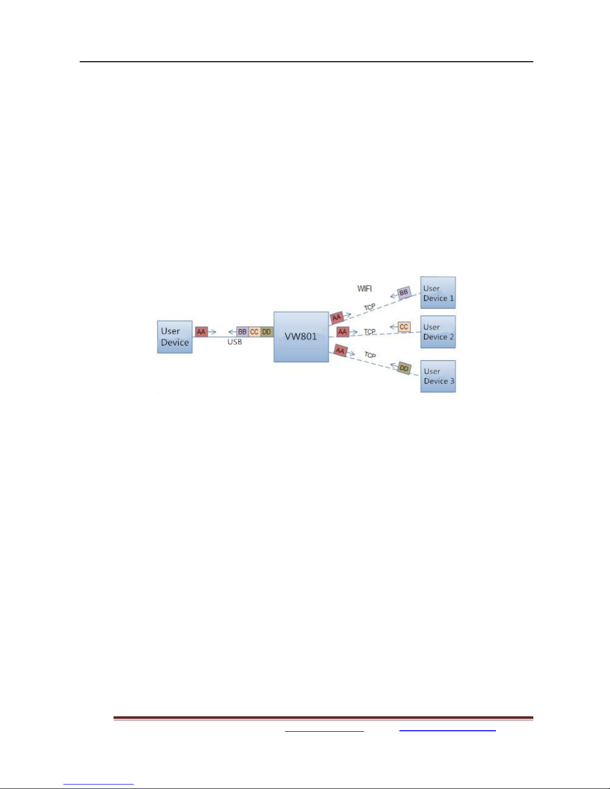
2.7. Multi-TCP Link Connection
When VW801 modem configured as a TCP Server, it supports Multi-TCP link connection, and
maximum 5 TCP clients are allowed. User can realize multi-TCP link connection at each operation
mode.
Multi-TCP link connection will work as following structure:
Upstream: All dates from different TCP connection or client will be transmitted to the serial port as a
sequence.
Downstream: All data from serial port (user) will be duplicate and broadcast to every TCP connection
or client.
Detailed multi-TCP link data transition structure as following figure:
Figure 6. Multi-TCP Link Data Transition Structure

VW801, VW802, VW803, VW804 Serial-WiFi Modem User Manual
Vitalwell Electronics (Zhuhai) Pte. Ltd. www.vital-well.com email: Vitalwell@vital-well.com 10
3. OPERATION GUIDELINE
3.1. VW801/ VW802/ VW803/ VW804 Usage Introduction
3.1.1. Software Tools
VW801 use two common software tools debugging and applying VW801 modem.
(User can also select other tools used to debug serial port).
Serial Debugging Software: Terminal
Ethernet Debugging Software: TCP to serial client software
3.1.2. Network Connection
User can select two methods to connect VW801 modem base on dedicated application.
Use VW801 STA interface. VW801 and debugged PC2 connect to a wireless AP,
Another PC1 (or user device) connect to VW801 modem with serial port:
Figure 7. STA Interface Debug Connection
Use VW801 AP interface. Debug PC2 connect to VW801 through wireless connection, another PC1
(or user device) connect to VW801 modem with serial port.
Figure 8. AP Interface Debug Connection

VW801, VW802, VW803, VW804 Serial-WiFi Modem User Manual
Vitalwell Electronics (Zhuhai) Pte. Ltd. www.vital-well.com email: Vitalwell@vital-well.com 11
3.1.3. Default Parameter Setting
Default SSID: VW801;
Default security mode: open, none;
User UART parameter setting:115200,8,1,None;
Default network parameter setti ng:TCP,Server,8899,10.10.100.254;
Module IP address: dhcp,0.0.0.0,0.0.0.0,0.0.0.0;
3.1.4. Modem Test
VW801 built in with a silabs USB-VCOM bridge chip: CP2102. Prior to use it, a driver is needed to be
installed. We can go to Silabs website www.silabs.com to get the latest driver. Alertly a copy of the driver
is put in the following link:
http://www.vital-well.com/webfile/software/CP210x_VCP_Windows.zip
when the driver is correctly installed, after plugging VW801 modem, a virtual COM port will be created.
To find the COM port number assigned by the system, you can
Right-click the icon "My Computer" ->”Properties”-> “Hardware" -> "Device Manager" -> "Ports (COM
& LPT) ", (in our example it is COM8, the port number will be different depending on the PC)
Open HyperTerminal serial software Terminal, the port number found in the above selected port number
(eg COM8),
set:
Baud rate: 115200 (default is 115200)
Data bits: 8
Parity: None
Stop bits: 1
Flow Control: None
Click "Connet"
 Loading...