

VitalWell VW1100A, VW2500A, VW1203A, VW1205A User Manual

V
i
t
a
l
W
e
l
l
E
l
e
c
t
r
o
n
i
c
s
P
t
e
L
t
d
.
VW1100A
VW2500A
VW1203A
VW1205A
USER MANUAL (Rev. 2.5B)
VitalWell Electronics Pte. Ltd.
V
i
t
a
T
e
l
:
T
e
l
:
vital-well.com
Block D2, #408/409, Southern Software Park, TangJia,, ZZhhuuHHaaii,, CChhiinnaa 551199008800
l
W
e
l
l
E
+
8
6
-
0
7
5
+
8
6
-
0
7
5
l
e
c
t
r
o
n
6
-
3
8
6
7
2
8
6
-
3
8
6
7
2
8
i
c
s
P
t
e
0
0
L
t
d
.

V
i
t
a
l
W
e
l
l
E
l
e
c
t
r
o
n
i
c
s
P
t
e
L
t
d
.
Proprietary Notice:
© Copyright VitalWell Electronics Pte. Ltd., 2005
The information in this document is subject to change without notice.
Company or product names mentioned in this document may be trademarks or
registered trademarks of their respective companies.
All rights reserved. Neither the whole nor any part of the information contained in
this publication may be reproduced in any material form except with the written
permission of VitalWell Electronics Pte Ltd..
This publication is intended only to assist the reader in the use of the product.
VitalWell Electronics Pte Ltd. shall not be liable for any loss or damage arising
from the use of any information in this publication, or any error or omission in
such information, or any incorrect use of the product.
Technical Support:
Documentation is updated periodically. For the latest information about VitalWell
Electronics Pte Ltd. products, including software upgrades and application
information, please contact your local VitalWell Electronics Pte Ltd. Sales entity.
VitalWell Electronics Pte Ltd. provides customer technical support using phone
and/or e-mail means.
For customer technical support, please contact your local VitalWell Electronics
Pte Ltd. sales entity.
V
i
t
a
T
e
l
:
T
e
l
:
vital-well.com
Block D2, #408/409, Southern Software Park, TangJia,, ZZhhuuHHaaii,, CChhiinnaa 551199008800
l
W
e
l
l
E
+
8
6
-
0
7
5
+
8
6
-
0
7
5
l
e
c
t
r
o
n
6
-
3
8
6
7
2
8
6
-
3
8
6
7
2
8
i
c
s
P
t
e
0
0
L
t
d
.

V
i
t
a
l
W
e
l
l
E
l
e
c
t
r
o
n
i
c
s
P
t
e
L
t
d
.
INTRODUCTION
The VW series Radio Modem provides the capability of a short range, reliable
wireless point-to-point, point-to-multipoint and mesh network RF data
communications link.
The VW series modem can be used in a variety of data communications
applications that require a simple to use invisible data link. The radio modem is
designed to interface to a variety of host devices. These devices include
computers, receipt printers, PLC’s, data loggers, SCADA devices and intelligent
control systems.
The serial data transferred over the radio link is not altered; the output serial data
stream is the same as the input serial data stream. The radio modems provide a
two-way data communications links, where each unit can accept serial data and
also output serial data.
The VW series radio modems are fully self-contained units, requiring only an
external +5VDC (or +3.3VDC) power source to operate. The radio modules used
in the radio modems have been selected to meet the requirements of unlicensed
operation in the international ISM bands, and are therefore acceptable for use in
many countries.
Features
§ 4 operation modes: Transparent mode, Transparent secured mode,
Addressed mode and Addressed secured mode
§ Repeater supported
§ Deep sleep mode
§ Server-Client mode
§ Broadcast Multi-drop mode
§ Serial protocol format is 9600bps,8 data/1 stop/no parity.
§ Selectable flow control of software/none.
§ Selectable radio speed, channel and radio power.
§ On-air data encryption, error checking and data acknowledgements.
§ Easy configuration by AT commands.
§ Built in configuration and diagnostic functions.
This manual describes the electrical specifications and different functioning
modes available on the VW series. This description will also help you to
understand the principles behind the configuration registers and to use them
more efficiently.
V
i
t
a
l
W
e
l
l
E
l
e
c
t
r
o
n
i
c
s
P
t
e
L
t
d
.
T
e
l
:
+
8
6
-
0
7
5
6
-
3
8
6
7
2
8
0
8
6
7
2
8
0
vital-well.com
T
e
l
:
+
8
6
-
0
7
5
6
-
3
Block D2, #408/409, Southern Software Park, TangJia,, ZZhhuuHHaaii,, CChhiinnaa 551199008800

V
i
t
a
l
W
e
l
l
E
l
e
c
t
r
o
n
i
c
s
P
t
e
L
t
d
.
CONTENTS
CHAPTER I ELECTRICAL SPECIFICATION ……………………………1
CHAPTER II CONFIGURATION MODE ……………………………………3
II.1 Entering Configuration Mode
II.2 Command Format
II.3 Configuration Commands in Detail
II.4 Registers Description
CHAPTER III TRANSPARENT MODE ……………………………….……9
III.1 Operation
III.2 Examples
CHAPTER IV TRANSPARENT SECURED MODE ……………………… 10
IV.1 Operation
IV.2 Examples
CHAPTER V ADDRESSED MODE …………………………………………11
V.1 Operation
V.2 Examples
CHAPTER VI ADDRESSED SECURED MODE …………… ………… …12
VI.1 Operation
VI.2 Examples
CHAPTER VII ORDERING INFORMATION ………………………………...13
APPENDIX …………………………………………………………………………...14
A. Modems and boards Installation: Principles and cautions
B. Register setting tips and examples
B.1. Configuration list file
B.2. Turn on Software flow control (Xon/Xoff)
B.3. Changing Operation Mode
B.4. A typical point-point configuration using Addressed Mode
B.5. A typical Server-Client configuration using Addressed Mode
B.6. A typical Hyper-terminal setting (Xon/Xoff enable)
V
i
t
a
T
e
l
:
T
e
l
:
vital-well.com
Block D2, #408/409, Southern Software Park, TangJia,, ZZhhuuHHaaii,, CChhiinnaa 551199008800
l
W
e
l
l
E
+
8
6
-
0
7
5
+
8
6
-
0
7
5
l
e
c
t
r
o
n
6
-
3
8
6
7
2
8
6
-
3
8
6
7
2
8
i
c
s
P
t
e
0
0
L
t
d
.

CHAPTER I ELECTRICAL SPECIFICATION
The VW series include 4 different models: RS232T, RS232C, RS485/422,
and USB. The radio performance is the same across all 4 models. They are
named by the different interfaces.
I.1 General Specifications
1)Supply Voltage:+5V (±20%)
2)Supply Current: < 100mA
3)Voltage level at I/O:+3.3V TTL( +5V compatible)
4):Serial Interface Characteristics (RS232)
i. Baud rate: 9600, 8N1. (Default)
5)RF Characteristics:
i. Frequency band:ISM 433/868/915MHz/2.4GHz
ii. Channels: 16 or 255(for 2.4GHz)
iii. RF rate:
1.2kbps, 2.4kbpa, 4.8kbps, 9.6kbps, 19.2kps,
38.4kbps, 76.8kbps,
115.2kbps, 256kbps ( VW1100A/VW2500A)
iv. Max RF transmitter power:
Sub-1G: +10dB; 2.4G : 0dB
v. Sensitivity:-116dB (2.4kbps), -108dB(38.4kbps)
vi. Typical link range (outdoor) :>1000m
I.2 Dimension
1) (L X W X H): 50mm X 25.2mm X 8mm (VW1100A, VW2500A)
60mm X 26mm X 9mm (VW1203A, VW1205A)
2) Interface: 9pin; 2.0mm header
I.3 Interface Specifications
I.3.1: VWxxxxA-232T
The RS232 signal voltage level is 3.3V TTL level at the interface, with
+5V compatible.
1) Signal Definitions:
Pin No. Signal Name Pin No. Signal Name
1 GND 6 I/O1
2 VCC (+5V) 7 I/O2
3 RXD (RS232,TTL) 8 I/O3
4 TXD (RS232, TTL) 9 N.C
5 I/O0 (Sleep /EN)
VitalWell Electronics Pte Ltd www.vital-well.com - 1 -
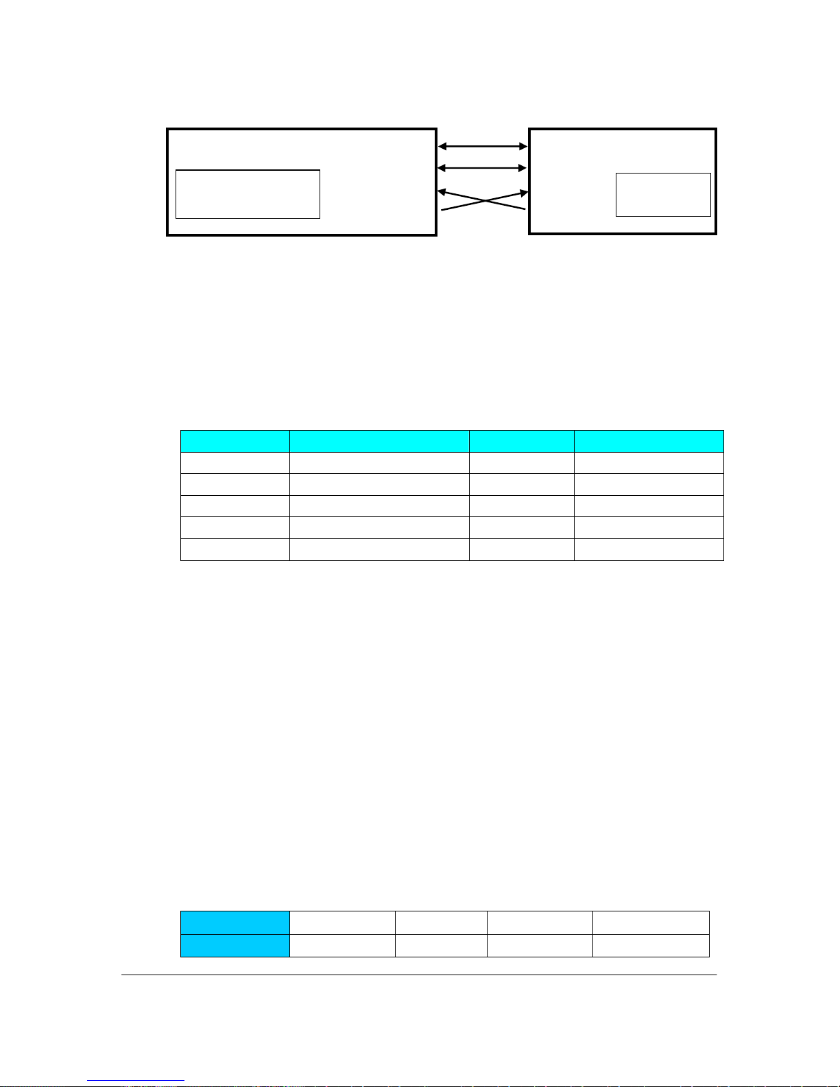
2) Typical Connections (connections at Pin1~4 only)
3(RXD)
RF-VW series
1 (GND)
2 (+5V)
4(TXD)
1(GND)
2 (+5V)
3(RXD)
4(TXD)
Host
I.3.2: VWxxxxA-232C
For the RS232 TXD/RXD signals, the voltage level at the interface
is RS232C level. The other signal assignment is the same as VW-232T.
I.3.3: VWxxxxA-485
Signal Definitions:
Pin No. Signal Name Pin No. Signal Name
1 GND 6 TD2 VCC (+5V) 7 I/O2
3 RD+ 8 I/O3
4 RD- 9 N.C
5 TD+
I.3.4: VWxxxxA-USB
The interface is USB. It will take power from the USB port. So no
external power supply needs. After installing a driver, it will create a
virtual serial port on the PC. All applications, which designed for serial
ports, will be able to work well with this module. E.g., It allows the PC to
use a normal hyper-terminal application to communicate with the module.
Please be noted, depends on the USB ports on the PC, the driver
will automatically create different “virtual” serial port numbers. For
example, the PC has 4 USB ports, say, we just name them at USB1,
USB2, USB3, USB4. When the module plugs into USB1, it may create a
virtual serial port, say COM3; When the module plugs into USB2, it will
create another virtual serial port, say COM4; then, COM5, and COM6, etc.
Signal Definitions:
Pin No. 1 2 3 4
Signal Name
+5V DM DP GND
VitalWell Electronics Pte Ltd www.vital-well.com - 2 -

CHAPTER II CONFIGURATION MODE
This section describes the configuration and test commands supported by the
radio modem. In most cases, once the configuration is set it will not need to be
changed. Configuration is performed using a serial terminal, or appropriate
communication application.
All commands and command values accepted by the radio modem are described
in this section; any entries other than those listed here results in an invalid
command or argument error message.
The first step to configuring the Radio Modem is to put it in Configuration Mode…
II.1 Entering Configuration Mode
A series of three consecutively typed characters, called an escape sequence,
forces the radio modem to exit data transfer mode and enter the modem
configuration mode. While in Configuration Mode, you can communicate directly
with the radio modem using a number of specific commands to configure and test
the radio modem.
The escape sequence is factory set to ‘+++’ (No carriage return key is followed). A
pause length of which is called the escape guard time (about 1s) must be
completed both before and after when escape sequence is entered. These three
'+' characters must not be sent as one continued frame. The delay between any 2
characters must be between 20ms~1s for the (‘+++’) sequence. This prevents
the radio modem from interpreting the escape sequence as data and the vice
versa. The guard time must also be met when the Radio Modem is initially
powered up.
Configuration changes are stored permanently in non-volatile memory within the
Radio Modem. Exiting Configuration Mode and returning back to data transfer
mode is accomplished by typing “ATO” at the command prompt. This will force a
soft reset of the Radio Modem resulting in any configuration changes taking
effect.
II.2 Command Format
VW modem’s parameters are set through the use of AT type commands sent on
the serial link.
'AT' commands complies with Hayes protocol used in PSTN modem standards.
This ‘AT’ protocol is used to configure the modem parameters, based on the
following principles :
VitalWell Electronics Pte Ltd www.vital-well.com - 3 -

A data frame always begins with the two ASCII ’AT’ characters, standing for
‘ATtention’,
_ Commands are coded over one or several characters and may include
additional data
_ A given command always ends up with a < CR> Carriage Return
A T Command Additional data <CR>
Note: The delay between 2 characters of the same command must be less
than 30 seconds
All alphabetical characters typed in configuration command mode are converted
to upper case before being interpreted by the configurator. Thus commands can
be typed using either upper or lower case.
Despite its similarity to standard telecommunication modem, it remains a radio
link modem and is consequently fitted with some particular and specific ‘AT’
commands proper to radio transmission (I.e. communication channel, radio
rate...).
VitalWell Electronics Pte Ltd www.vital-well.com - 4 -
 Loading...