

Page 1
Vitalograph ALPHA User Manual
07368
Issue 2
Vitalograph
alpha
MODEL 6000
User Manual
l
Copyright Vitalograph 2007
Page 2

Vitalograph ALPHA User Manual
07368
Issue 2
Copyright Vitalograph 2007
Vitalograph Ltd., Maids Moreton, Buckingham, MK18 1SW, England
Phone: (01280) 827110 Fax: (01280) 823302
e-mail: [email protected]
Vitalograph GmbH, Jacobsenweg 12, 22525 Hamburg, Germany
Phone: (040) 54 73 91-0
Fax: (040) 547 391 40
e-mail: [email protected]
Vitalograph Inc., 13310 West 99
th
Street, Lenexa, Kansas 66215, U.S.A.
Phone: (913) 888-4221 Fax: (913) 888-4259
e-mail: [email protected]
Vitalograph (Irl.) Ltd., Gort Road Business Park, Ennis, Co. Clare, Ireland
Phone: (065) 6864100 Fax: (065) 6829289
e-mail: [email protected]
Internet: www.vitalograph.com
© Copyright Vitalograph 2007
Current Edition (Issue 2)
Cat. No. 07368
Vitalograph is a registered trademark
Page 3

Table of Contents
DESCRIPTION OF THE VITALOGRAPH ALPHA 1
MAIN COMPONENTS OF THE VITALOGRAPH ALPHA 1
FEATURES OF THE VITALOGRAPH ALPHA 1
GETTING THE VITALOGRAPH ALPHA READY FOR USE 2
POWER MANAGEMENT IN THE VITALOGRAPH ALPHA 2
BATTERY PACK 2
BATTERY LOW DETECT 3
OPERATING THE VITALOGRAPH ALPHA 3
ENTERING SUBJECT INFORMATION 3
PERFORMING A TEST SESSION 4
Checks to Make before Performing a Test Session 4
Performing a VC Test 4
Performing an FVC Test 6
SAVING THE TEST SESSION. 7
PERFORMING A POST TEST SESSION 8
PRINTING THE TEST SESSION 8
CLEAR RESULTS 9
CHECKING ACCURACY 9
When to Check Accuracy 10
VIEWING CURRENT SUBJECT DETAILS 10
DELETING STORED SUBJECTS/TEST RESULTS 11
CONFIGURATION OPTIONS 11
Preferences 11
Date/Time 12
Report Settings 13
Syringe/Calibration 13
Sound Volume 15
FITTING A NEW PAPER ROLL 15
CLEANING INSTRUCTIONS 16
CLEANING AND DISINFECTING THE VITALOGRAPH ALPHA 16
DISASSEMBLING THE FLEISCH FLOWHEAD 19
REASSEMBLING THE FLEISCH FLOWHEAD 20
FAULT FINDING GUIDE 21
i
Page 4

CUSTOMER SERVICE 23
CONSUMABLES AND ACCESSORIES 23
EXPLANATION OF SYMBOLS 24
OTHER LABELS 24
TECHNICAL SPECIFICATIONS 24
CE NOTICE 25
FDA NOTICE 29
DECLARATION OF CONFORMITY 30
GUARANTEE 31
ii
Page 5
Vitalograph ALPHA User Manual
07368
Issue 2
A
D
E
B
C
Figure 1
Copyright Vitalograph 2007
Page 6

DESCRIPTION OF THE VITALOGRAPH ALPHA
The Vitalograph ALPHA is a desktop spirometer designed for use by
trained professionals in the doctor’s office, clinic, hospital department,
etc. for measuring and archiving tests on human subjects.
Demographic data are uploaded or entered via a keypad and stored,
together with spirometry test data. Current test data can be viewed on
the LCD and printed and downloaded to a PC. There are a variety of
backup and other configuration options.
Information about the software can be obtained from the About box.
This information can be used if any queries are made to Vitalograph or
a service agent.
To access the About box:
1. Press 8 (Configuration) from the Main Menu.
2. Press 6 (About the ALPHA)
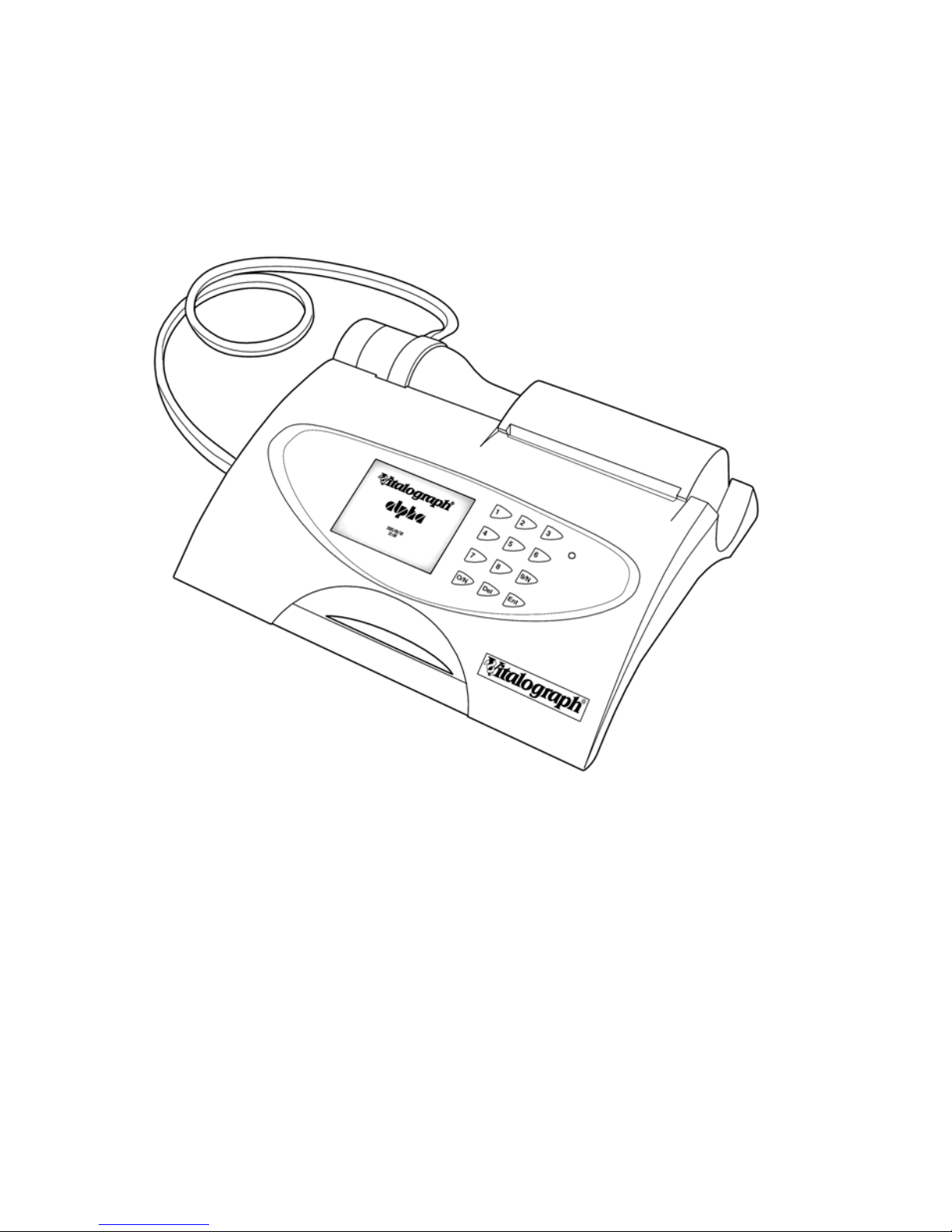
MAIN COMPONENTS OF THE VITALOGRAPH ALPHA
A Vitalograph ALPHA device
B LCD
C Keypad
D Flowhead
E Printer
FEATURES OF THE VITALOGRAPH ALPHA
The Vitalograph ALPHA’s features include:
Very high accuracy, linearity and stability •
•
•
•
•
•
Extremely simple to operate keypad with extra-large buttons
Integral printer for instant results or printing to the Vitalograph
Report Utility
Storage of tests and demographic information
Ability to exchange information with a PC
Robust, proven fleisch-type flowhead. No moving parts or delicate
sensors
• Simple cleaning. The flowhead completely dismantles for washing,
disinfecting or even autoclaving.
1
Page 7

GETTING THE VITALOGRAPH ALPHA READY FOR USE
1. Attach the flowhead to the Vitalograph ALPHA by the dual silicone
tubing (Flowhead Connection Tube). Ensure that the
coloured/ribbed tapping on the flowhead is connected to the ribbed
side of the connection in the housing.
2. Open the printer door and feed the paper through the printer (See
section Fitting a New Paper Roll).
3. Only use the Vitalograph ALPHA with the purpose-built low voltage
power supply unit with which it is supplied. Attempted use with
other power sources may cause irreparable damage and invalidate
the warranty. The output from the power supply is 12 volts DC.
4. Connect the jackplug from the power supply into the socket on the
rear of the Vitalograph ALPHA. Plug the mains plug into a suitable
socket, operate the On/Off switch on the rear of the instrument and
the Vitalograph ALPHA is ready for use.
5. For portability the Vitalograph ALPHA comes fitted with
rechargeable batteries, which allows the device to be used for a
period of time without the mains connected.
POWER MANAGEMENT IN THE VITALOGRAPH ALPHA
The Vitalograph ALPHA can be powered using the purpose-built low
voltage Power Supply unit with which it is supplied or from the internal
Battery Pack. When powered from the low voltage Power Supply the
LED on the front face on the device will be green. The LED will be
orange when the device is powered from the Battery Pack.
Battery Pack
The Vitalograph ALPHA is fitted with a rechargeable Battery Pack. This
allows the device to be used without the 12V Power Supply connected.
The battery pack can be re-charged by plugging in the 12 V Power
Supply. To fully re-charge switch off the Vitalograph ALPHA and leave
it plugged in over-night.
The battery pack can also be re-charged by connecting the device to a
PC via the USB cable. The USB connector is located on the right side
of the device. Switch off the Vitalograph ALPHA when re-charging the
batteries via USB.
Note: Operating the Vitalograph ALPHA device from the USB is not
possible. The USB can be used to re-charge the batteries only.
2
Page 8
Battery Low Detect
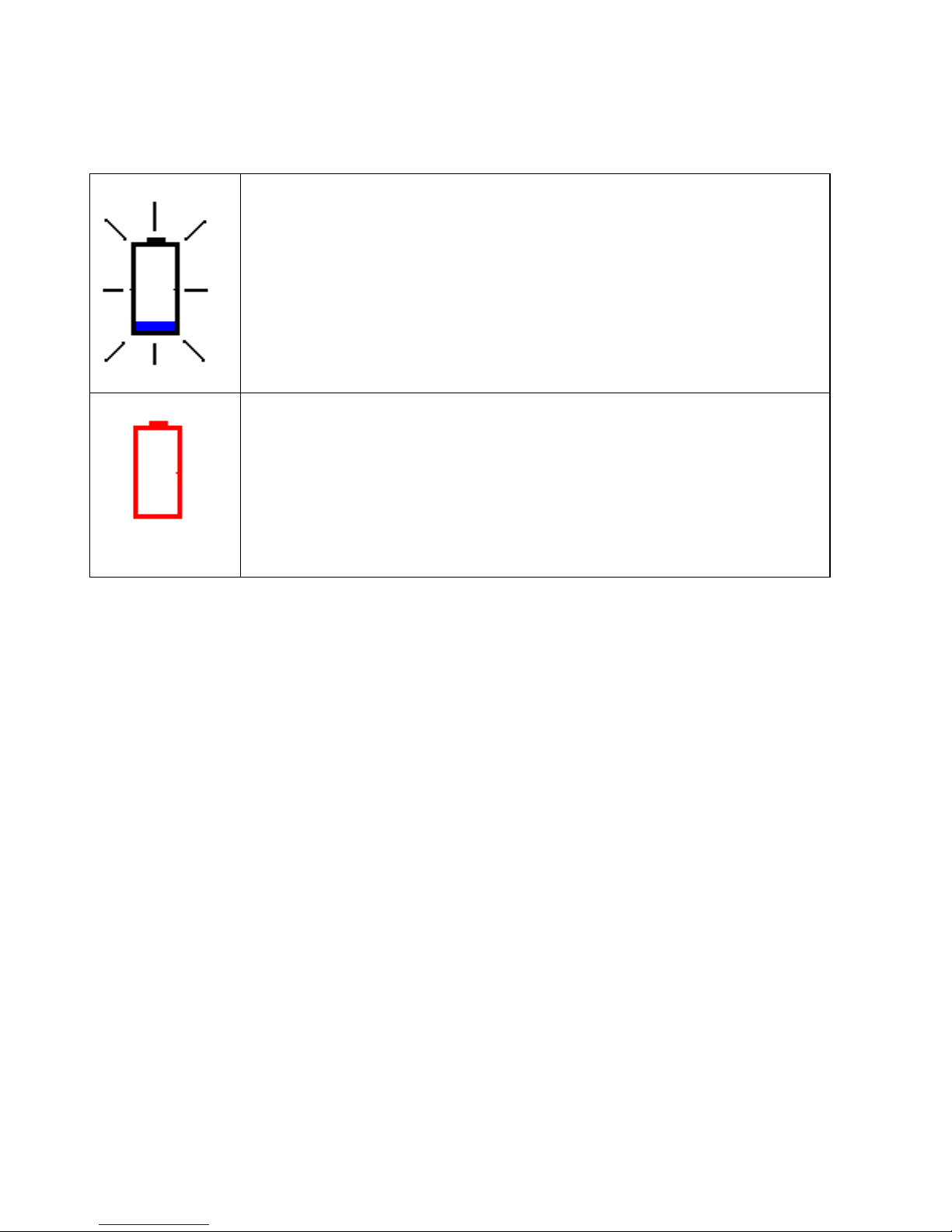
The Vitalograph ALPHA has a number of battery power detect
messages:
When the Battery Pack starts to run low the Battery Low
icon will flash on and off on the Main Menu screen.
You will be allowed to continue to use the device. It is
advised that you plug in the 12V Power Supply to recharge the batteries and continue testing.
When the Battery Pack is approaching fully discharged
the Battery Discharged icon will appear continuously on
the Main Menu screen.
If you press any of the keys a warning message will
appear and you will not be allowed to proceed into any
other screen. Plug in the 12V Power Supply to recharge the batteries and continue testing.
OPERATING THE VITALOGRAPH ALPHA
Entering Subject Information
After turning on the device, you are presented with the New Subject
screen. A series of dialog boxes appear in which you enter information
using the keypad. Instructions appear at the bottom of the screen to
guide you through the information to be entered. Once you are ready to
move onto the next dialog box, press the ‘Enter’ key on the keypad.
These dialog boxes appear one at a time in the following order:
1. Reference Number
2. Age
3. Height
4. Gender
5. Population Group
When entering subject information, you can specify the
population group of the subject. There are a number of population
groups to select from. These population groups have an
associated predicted normal set and correction factor. These
normal sets are usually based on sex, age and height and are
useful when comparing a subject’s test results with predicted
normal values from a suitable reference population.
3
Page 9

6. Weight
7. Smoking History
If you wish to change the data entered press the ‘Delete’ key and enter
the data again. Pressing the ‘Delete’ key repeatedly will step back
through the dialogue boxes. Once you have finished entering the data
press the ‘Enter’ key to bring you to the Main Menu.
The Population Group, Weight and Smoking History fields may not
appear in the New Subject screen. This is dependent on the variant of
the device.
Note: The Subject Information will now be printed to the internal printer
if it is selected.
If you wish to enter different subject details select the ‘New Subject’
option from the Main Menu using the keypad. You will be asked if you
wish to clear results.
• Press Yes to bring you to the New Subject screen, and enter
the New Subject details as outlined above.
• Press No to bring you back to the Main Menu.
Performing a Test Session
Checks to Make before Performing a Test Session
Before starting a test session, there are a number of checks which
should be made:
1. Ensure that the accuracy of the Vitalograph ALPHA unit was
checked recently. (Refer to the section on Checking Accuracy
)
2. Ensure all the required demographic information is entered for the
subject.
Performing a VC Test
Perform the VC test as follows:
1. Select the ‘VC Test’ option from the Main Menu using the keypad.
2. Wait for the ‘Exhale to Begin’ icon to appear.
This indicates that the Vitalograph ALPHA unit is ready to accept a
blow.
4
Page 10

Note: You can view the results as either a Volume/time graph or a
Volume bar graph:
a. Press key 1 for Volume/time (V/t) graph.
b. Press key 2 for Volume bar graph.
3. The VC test can be performed using two methods. Read either of
the following instructions to the subject so that testing is performed
properly:
Method 1:
a. Stand up
b. Keep the flowhead away from your mouth.
c. Inhale as deeply as possible and insert the bacterial viral
filter into your mouth, clamping it between your teeth.
d. Close your lips around the bacterial viral filter.
e. Exhale normally for as long as possible.
Method 2:
Note: Method 2 can only be used when the Volume/Time (V/t) graph
is selected as the display option. This method cannot be used when
the Volume bar graph is selected as the display.
a. Stand up.
b. Insert the bacterial viral filter into your mouth and,
clamping it between your teeth.
c. Close your lips around the bacterial viral filter.
d. Breathe in and out normally. This is tidal breathing.
When you are happy that the subject has achieved steady
tidal breathing, continue with:
e. Exhale as deeply as possible.
f. Inhale as much as possible (speed is not important) and
when fully inhaled.
g. Return to tidal breathing, i.e. breathe in and out normally
again.
The VC values recorded for the blow are tabulated. The best VC
value for the current session and the Lower Limit of Normality
(LLN) are also displayed.
5
Page 11

4. Repeat to perform another VC test if required.
5. After performing the VC tests press the ‘Enter key’ to exit the VC
Test screen. This brings you back to the Main Menu.
Performing an FVC Test
1. Select the ‘FVC Test’ option from the Main Menu using the keypad.
2. Wait for the ‘Exhale to Begin’ icon to appear.
This indicates that the Vitalograph ALPHA unit is ready to accept a
blow.
Note: You can view the results as either a Volume/time (V/t) or a
Flow/Volume (F/V) graph:
a. Press key 1 for Volume/time graph.
b. Press key 2 for Flow/Volume graph.
3. The FVC test can be performed using 2 methods as follows. Read
either of the following instructions to the subject so that testing is
performed properly:
Method 1:
a. Stand up.
b. Keep the flowhead away from your mouth.
c. Inhale as deeply as possible, then inset the bacterial viral
filter into your mouth, clamping it between your teeth.
d. Close your lips around the bacterial viral filter.
e. Exhale as much and as quickly as possible and try to keep
exhaling for at least 6 seconds.
f. If inspiratory indices are selected, then inhale as quickly as
possible.
Method 2:
a. Clip on the nose clip to seal your nose.
b. Put the bacterial viral filter (BVF) into your mouth, biting it
lightly.
c. Seal your lips around the mouthpiece
6
Page 12

d. Breathe in and out normally. This is called tidal breathing.
When you are happy that the subject has achieved steady tidal
breathing, continue with:
e. Inhale as deeply as possible
f. Exhale as much and as quickly as possible, and when fully
exhaled
g. Inhale fully as quickly as possible
h. Return to tidal breathing, i.e. breathe in and out normally
again.
4. The FVC, FEV1, FEV1ratio and PEF values recorded for the blow
are tabulated. The best FVC, FEV1, FEV1ratio and PEF for the
current session are displayed.
The test quality (QA) is shown at the bottom of the test screen.
The number of tests performed and the Test Grade are shown in
the V/t screen. Each test series is graded in relation to its
repeatability between acceptable manoeuvres. The quality Grades
are A, B, C, D and F.
The repeatability (Within) of FVC and FEV1 are shown in the F/V
screen. The repeatability information is displayed if at least two
tests are performed. I Bars on the F/V graph are shown for FEF25,
FEF 50 and FEF75. An I Bar for FVC is also shown on the Volume
axis. The upper mark on the I Bars indicates the predicted value
for the subject. The lower mark on the I Bar indicates the LLN value
for the subject. The I Bars are based on the predicted sets and will
be shown if sufficient subject demographics information is entered.
5. Repeat to perform another FVC Test if required.
6. After performing the FVC tests press the ‘Enter’ key to exit the FVC
Test screen. This brings you back to the Main Menu.
Saving the Test Session.
1. Select ‘Post Mode’ from the Main Menu using the keypad.
2. Select ‘Save Current Subject Pre Test’ from the Post Mode screen
using the keypad. A message will appear informing you of the
memory location where the test session will be saved. There are
7
Page 13

nine memory locations on the Vitalograph ALPHA. The best three
tests will be saved.
Note: If a Compact Flash card is inserted into the Compact Flash
connector at the right side of the device, then all test blows and not just
the best three will be saved to the Compact Flash card. Results are
saved as per the format outlined in the European Respiratory Journal,
2005; 26: Pages 319-338: ATS/ERS Task Force: Standardisation of
Lung Function Testing.
Performing a Post Test Session
A Post test session can be performed on an FVC test session following
the administration of drugs. Post drug delivery performance is
measured versus pre delivery.
To perform a Post test:
1. Select ‘Post Mode’ from the Main Menu using the keypad.
2. If you want to perform a Post Test on the Pre-test Session just
performed select ‘Set Post Mode for Current Subject’. This will
return you to the Main Menu screen. The text Post Mode will
appear on the top right hand corner of the screen.
3. If you wish to perform a Post Test on a different subject or Pre-test:
a. Select ‘Select a Subject from the Pre-Store’.
b. A message ‘Warning! Current Results will be cleared’
will appear. Select Yes and the Select Subject screen
will appear.
c. Select the number of the Pre-test you wish to perform
the Post test on. This will return you to the Post Mode
screen.
d. Press ‘Enter’ to return you to the Main Menu screen.
4. Perform the Post FVC test as outlined in section Performing a Test
Session.
Note: If there is no Pre-Test performed, the message No FVC Tests
Performed will appear.
Printing the Test Session
You can print the current test session for the subject by selecting ‘Print’
from the Main Menu.
8
Page 14

The Vitalograph ALPHA has an internal printer. It can also be
connected through the USB port at the side of the unit to the
Vitalograph Reports Utility, so that the report can be written to a PC.
The information printed on the session report can be configured to suit
individual requirements. Refer to section on Report Settings
.
The test parameters on the report will vary according to regional
requirements. The test parameters and their definitions are available
from the Help files, which can be accessed from the Main Menu.
Note: The internal (thermal) printout will fade over time when exposed
to light or heat. If a permanent record is required, photocopy the
thermal printout or send the report to the Vitalograph Reports Utility.
Refer to the section on Configuration
for information on selecting the
internal or Vitalograph Reports Option.
Clear Results
If you wish to delete the current session you can do this as follows:
1. Select the ‘Clear Results’ option from the Main Menu using the
Keypad.
2. A message will appear ‘Warning! Current Results will be Cleared.
Do you wish to proceed?’ in the Clear Results screen. Select
‘Yes’ to delete the current results and return to the Main Menu.
Select ‘No’ to cancel the delete and return to the Main Menu.
Checking Accuracy
All spirometry standards (e.g. ATS/ERS/BTS/ANZRS) recommend
9
checking the accuracy of lung function measuring devices at least daily
with a 3-L syringe to validate that the instrument is measuring
accurately. The Vitalograph ALPHA should never be outside accuracy
limits unless damaged or in a fault condition. In this event, see the
fault-finding guide
. In normal use, calibration traceability certification is
recommended as a part of the routine annual service.
Page 15

ATS recommendations require that the difference between the volume
measured by the spirometer and the volume pumped into the
spirometer from a syringe is within 3%.
Follow these steps to check the accuracy of the unit.
1. Select Accuracy Check from the Main Menu using the keypad.
2. Pump air through the flowhead to bring it to ambient
temperature.
If the flowhead has very recently been used for testing or has
come from a cold environment, its temperature should be
equilibrated with ambient by pumping air through it from the
syringe several times.
3. Press the ‘Enter’ key to bring you into the Accuracy Check
screen and follow the on-screen instructions.
Note: Note: Press the ‘Del’ key to exit the Accuracy Check
screen and return to the Main Menu. The accuracy check will not
be logged to the Vitalograph ALPHA memory in this case.
4. If an Accuracy Check report is required select the Report option.
Note: If the device is outside calibration you will be given the
option to update the calibration. If you select this option you will
be brought through the accuracy check routine again.
When to Check Accuracy
• In accordance with your own established procedures
• After annual maintenance checks
• After cleaning or disassembling spirometer for any reason
• After adjusting calibration
• If the flowhead has been dropped.
Viewing Current Subject Details
To view the Current Subject details:
1. Select ‘Post Mode’ from the Main Menu using the keypad.
2. Select ‘View Current Subject’ from the Post Mode screen.
3. The Current Subject screen will be displayed.
Note: You will not be able to modify any of the subject details.
10
Page 16

Deleting Stored Subjects/Test Results
To delete individual Stored Subjects/Test results:
1. Select ‘Post Mode’ from the Main Menu using the keypad.
2. Select ‘Delete Stored Tests’ from the Post Mode screen.
You are presented with the list of the Subjects and the associated
test stored on the device. A maximum of nine Subject/Tests can
be stored on the device in locations 1-9 as indicated in the Delete
Subject screen.
3. Select the number of the Subject/Test you wish to delete using
the keypad. This location will then be marked as ‘Empty’.
4. Continue to delete test as required.
5. Press ‘Enter’ to return to the Post Mode screen.
To delete all Stored Subjects/Test results:
1. Select ‘Post Mode’ from the Main Menu using the keypad.
2. Select ‘Clear Pre Store’ from the Post Mode screen.
3. A message ‘Warning! All data in pre store will be cleared. Do you
wish to proceed?’ will appear in the Clear Results screen.
4. Select ‘Yes’ to delete the all data and return to the Post Mode
screen. Select ‘No’ to cancel the delete and return to the Post
Mode screen.
Configuration Options
There are a number of Configuration options available on the
Vitalograph ALPHA device. To access these, press the ‘Configuration’
option on the Main Menu using the keypad. The options available are:
Preferences
This will allow you to configure the device to your own requirements.
Selecting this will give you the following options:
Printer
This allows you to either print the test report to the Internal Printer or
send it to the Vitalograph Reports Utility on a PC. Press key ‘1’ on
the keypad to switch between the two options.
Note: In order to send the report to the Vitalograph Reports Utility it
is necessary to have the Vitalograph Reports Utility installed on your
11
Page 17

PC and the Vitalograph ALPHA connected to your PC via a USB
cable.
Units
This allows you to select the units as Metric or US (Imperial). Press
key ‘2’ on the keypad to switch between the two options.
Graph Type
This allows you to select the graph type to be shown as default in
the FVC test screen, Press key ‘3’ on the keypad to switch between
the Volume/Time (V/T) and Flow/Volume (F/V) graphs.
Test Acceptability
This allows you to manually accept the tests performed, or allow the
device to determine test acceptability (automatic). Press key ‘4’ to
switch between Manual and Automatic.
VC Test Type
This allows you to select the graph type to be shown as default in
the VC test screen, Press key ‘5’ on the keypad to switch between
the Volume/Time (V/T) and Volume Bar graphs.
Date/Time
1. Select ‘Date/Time’ from the Configuration screen using the
keypad.
2. In the Date/Time screen press key ‘1’ to change the year. Enter
the revised year as required using the keypad and press ‘Enter’.
The Month, Day, Hour and minute fields are modified in the same
way.
3. To modify the Date Format press key ‘6’ to switch between the
different date formats:
DD/MM/YYYY
MM/DD/YYYY
YYYY/MM/DD
4. Press ‘Enter’ to save the change.
5. To modify the Time Format press key ‘7’ to switch between 24
hour and 12 hour.
6. Press ‘Enter’ to save the change.
7. Once you have finished modifying the date and time settings
press ‘Enter’ to save the changes and return to the
12
Page 18

Configuration screen. Press ‘Delete’ to cancel the changes
made and return to the Configuration screen.
Report Settings
The information printed on the session reports can be configured to
suit individual requirements. The Vitalograph ALPHA can print to the
internal printer or send the report to the Vitalograph Reports Utility.
1. Select ‘Report Settings’ from the Configuration screen using the
keypad. You are presented with the list of items that can be
configured on the test reports.
2. In the Report Settings screen press key ‘1’ to switch the
Volume/time (V/t) graph on or off.
3. Press key ‘2’ to switch the Flow/Volume (F/V) graph on or off.
4. Press Key ‘3’ to switch the Comments on of off.
5. Press key ‘4’ to switch the Test QA messages on or off.
6. Press key ‘5’ to switch the Interpretation of the test results on or off.
7. Press key ‘6’ to switch between showing SDS (Standard Deviation
Score) or %Predicted in the session table of results. In the session
table of results the % of Predicted value will be printed by default. If
SDS is on, the SDS (Standard Deviation Score) will be printed
instead.
8. Press key ‘7’ to either show the Best Test only on the report or the
Three Tests saved to the database.
9. Press key ‘8’ to switch colour on or off. This option is not available
for the internal printer.
10. When you have finished modifying the Report Settings press
‘Enter’ to save the changes and return to the Configuration
screen. Press ‘Delete’ to cancel the changes made and return to
the Configuration screen.
Syringe/Calibration
The Vitalograph ALPHA should never be outside accuracy limits unless
damaged or in a fault condition. In this event, see the fault-finding
guide. In normal use, calibration traceability certification is
recommended as a part of the routine annual service.
1. Select the Syringe/Calibration menu using the keypad. You are
presented with three options:
a. Set Syringe Volume
b. Linearity Check
c. Calibration
13
Page 19

Set Syringe Volume:
i. Select Precision Syringe from the
Syringe/Calibration screen using the keypad.
ii. Follow on screen instructions to enter the
volume of the calibrated syringe you are using.
iii. Press ‘Enter’ to save the new volume entered
and return to the Syringe/Calibration screen.
Press Delete to cancel the changes made and
return to the Syringe/Calibration screen.
Linearity Check
i. Select Linearity Check from the
Syringe/Calibration screen using the keypad.
ii. Pump air through the flowhead to bring it to
ambient temperature. If the flowhead has very
recently been used for testing or has come from
a cold environment, its temperature should be
equilibrated with ambient by pumping air.
iii. Press the ‘Enter’ key to bring you into the
Linearity Check screen.
iv. Using a 3L Calibrated syringe pump air into the
flowhead at a slow rate of <2L/s. Immediately
withdraw the syringe at a slow rate. This
manoeuvre should show on the graph between
the two red lines. If it is a correct manoeuvre
the table on the screen will show ‘Test 1’, and
the FVC and FIVC values will be updated.
Note: Press the ‘Del’ key to exit the Linearity
Check screen.
v. Repeat for the slow rate three times in total.
vi. Repeat the procedure outlined in iv & v for a
medium rate >2L/s and <6L/s. This manoeuvre
should show on the graph between the red and
green lines. If it is a correct manoeuvre the test
number and the FVC and FIVC values will be
updated in the table.
vii. Repeat for the medium rate three times in total.
viii. Repeat the procedure outlined in iv & v for a
fast rate >6L/s. This manoeuvre should show
14
Page 20

on the graph between outside green lines. If it is
a correct manoeuvre the test number and the
FVC and FIVC values will be updated in the
table.
ix. Repeat for the medium rate three times in total.
x. When all the manoeuvres are complete press
‘Enter’ for the result.
xi. If a Linearity Check report is required select the
Report option.
Calibration
i. Select Calibration from the Syringe/Calibration
screen using the keypad.
ii. Pump air through the flowhead to bring it to
ambient temperature. If the flowhead has very
recently been used for testing or has come from
a cold environment, its temperature should be
equilibrated with ambient by pumping air
through it from the syringe several times.
iii. Press the ‘Enter’ key to bring you into the
Calibration screen and follow the on-screen
instructions.
Note: Press the ‘Del’ key to exit the Calibration
screen.
iv. If a Calibration report is required select the
Report option.
Sound Volume
1. Select the ‘Sound Volume’ option from the Configuration screen
using the keypad.
2. Adjust the sound level up by pressing key ‘2’.
3. Adjust the sound level down by pressing key ‘8’.
4. When you have finished changing the sound level press ‘Enter’ to
save the changes and return to the Configuration screen.
Fitting a New Paper Roll
The Vitalograph ALPHA is supplied with a roll of paper fitted into the
printer. (Note: The outside of the roll will not give a strong print
impression due to loss of sensitivity on exposure to light.).
15
Page 21

To replace the paper:
1. Open the printer door using the finger catch on each side of the
door. This will expose the head of the printer and the paper roller
mechanism.
2. Take out the empty roll by unclipping the roll support rod from the
holder.
3. Put the roll support rod into the new roll of paper and unroll about
15 cm (6 inches) of paper. (Note: To make fitting easier create a
point in the middle of the paper by tearing off the two corners of the
leading edge of the paper.)
4. Lay the paper roll between the back of the Vitalograph ALPHA unit
and the inside of the open door, with the paper coming out from the
bottom of the roll and pointing toward the printer. This will allow you
more access to the printer feed mechanism.
5. In the home screen, lift the green lever on the printer.
6. Feed the leading edge of the paper into the bottom slot of the
printer until the paper appears through the top of the printer. The
paper can now be pulled through. To aid in feeding the paper
through the printer, press the ‘Enter’ key on the Main Menu screen.
This will feed a short length of paper through the printer.
7. Close the green lever.
8. Fit the new paper roll onto the holding clips.
9. Hold the paper over the paper tear bar and close the door.
Note: The Vitalograph logo should appear on the right edge of the
paper and be facing you.
Warning: Paper tear bar contains sharp edges. Users should take
care not to cut/scrap their fingers.
CLEANING INSTRUCTIONS
Cleaning and Disinfecting the Vitalograph ALPHA
A new mouthpiece (either SafeTway or BVF) should be used for each
subject. A delay of at least 5 minutes should be allowed between
subjects to allow settling of previously aerosolized particles in the
measuring device.
16
Page 22

It is recommended that the flowhead be regularly cleaned according to
the guidelines of the user’s facility.
In the event of visible contamination of the flowhead cones or flowhead
element, they should be cleaned or disinfected as described in the
accompanying table. The flowhead conditioning meshes should also
be replaced in the event of damage, or if visibly contaminated.
The frequency of cleaning and disinfecting is dependent on the
Facility’s Risk Assessment, usage, and test environment, but it should
be at least monthly or every 100 subjects (500 blows).
It is recommended that the flowhead—flowhead complete and
flowhead connection tube—be replaced annually.
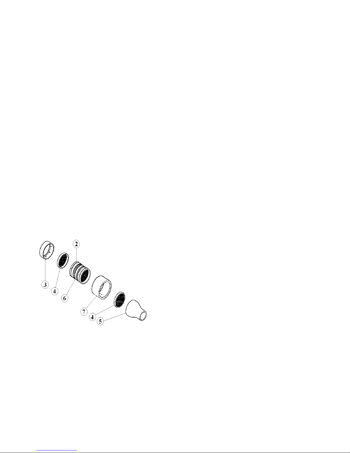
Refer to Figure 2 for identification of parts.
17
Page 23

Table of Materials Used & Cleaning/Disinfection Methods
This listing of materials used is given to provide users with information
to allow the assessment of other cleaning and disinfecting procedures
available in the facility on this device.
Part Material Clean/
Disinfect
Autoclave
Possible?
Recommended
Disinfectants
Case
Exterior
ABS Clean No
White
Flowhead
Tube
Silicone
Rubber
Clean Viable
Wiping with a 70%
isopropyl alcohol
impregnated cloth
provides a suitable form of
cleaning and low-level
disinfection. This may be
preceded by cleaning with
an anti-static foam cleaner
if necessary. Note:
Ensure isopropyl alcohol
does not come in
contact with the screen.
Warning: Paper tear bar
contains sharp edges.
Users should take care not
to cut/scrap their fingers.
Screen Electrode
with AntiNewtonRing
Treatment
Clean No
Lightly wipe the surface
with cotton pad or other
soft material. NOTE: DO
NOT use chemicals such
as acetone, toluene,
ethanol or isopropyl
alcohol. DO NOT wipe in
a circular motion.
Strokes should be either
up/down or over/back.
Fleisch
Element
Aluminium,
Stainless
Steel
Clean Viable
Flowhead
Body
Aluminium
& Acetyl
Clean &
Disinfect
No
Flowhead
Cone
TPX Clean &
Disinfect
Viable
Flowhead
End Cap
TPX Clean &
Disinfect
Viable
Flow
Conditioning
Meshes
Acetyl and
Polyester
Dispose No
Disinfect by immersion in
sodium
dichloroisocyanurate
solution at 1000 ppm
concentration of free
chlorine for 15 minutes
(see following section for
recommended
cleaning/disinfection
method for the Vitalograph
ALPHA Flowhead) The
flowhead may also be
disinfected by autoclaving
at 134°C for 3 minutes or
120°C for 20 minutes.
All external parts of the Vitalograph ALPHA require cleaning, i.e. the
removal of visible particulate contamination. The parts of the
Vitalograph ALPHA that make up the flowhead, which comes into
18
Page 24
contact with subjects being tested, also require disinfecting. A
spirometer is not designed as a ‘sterile’ device.
Definitions of cleaning and disinfection are as defined in “Sterilization,
Disinfection and Cleaning of Medical Equipment: Guidance on
Decontamination from the Microbiology Committee to Department of
Health Medical Devices Directorate, 1996”.
Recommendations for chemical disinfectants are derived from the
PHLS publication “Chemical Disinfection In Hospitals 1993”.
Disassembling the Fleisch Flowhead
1. Remove the cone and the end cap from the flowhead.
2. Remove the flow conditioning meshes from inside the cone and the
end cap, and discard them.
3. To remove the flowhead body from the fleisch element, place the
fleisch element on a hard, flat surface with the largest diameter at
the top. Push down on the flowhead body with thumbs and
forefingers until it reaches the flat surface. A final pulling and
twisting action will separate the parts.
1. Flowhead Complete – 61030
2. 'O' rings - 2120013
3. Flowhead End Cap -62006SPR
4. Flow Conditioning Meshes - 42084
5. Flowhead Cone - 62019SPR
6. Fleisch Element - 62055SPR
7. Flowhead Body – 61020
8. Lubrication: Silicone Grease – 30961SPR
Figure 2: Flowhead Assembly
4. Clean each separate part of the flowhead by washing in a mild
detergent and removing particulate contamination. To clean the
fleisch element, swill vigorously in water with mild detergent or use
an ultrasonic bath. Do not attempt to “rub” or “scrub” at capillaries.
19
Page 25

The flowhead body (7) does not require disinfection, but may be
cleaned/disinfected with the rest of the flowhead for convenience.
5. Rinse all parts in clean water.
6. Disinfect by immersion in sodium dichloroisocyanurate (NaDCC)
solution at 1,000 ppm concentration of free chlorine for 15 minutes.
Prepare disinfectant solution as directed in the manufacturer’s
guidelines.
7. Rinse with very hot water to aid later drying.
8. Leave to dry completely before reassembling. Drying the fleisch
element components may require placing them in a warm place
overnight. A drying cabinet is ideal.
Always follow the safety guidelines given by the manufacturer of
cleaning and disinfectant chemicals.
Reassembling the Fleisch Flowhead
1. Examine the fleisch element to ensure that no liquid or particles
remain in the holes, grooves or pressure tappings.
2. Check the 'O' rings for damage and ensure that they are correctly
positioned within the grooves.
3. Apply a very small amount of silicone grease to ‘O’ Rings and
inside the surfaces of the flowhead body. Wipe off any visible
amounts of grease. Ensure that the tiny annular holes on the
outside of the fleisch element are not blocked.
4. When re-assembling the flowhead, ensure that the blue pressure
tapping is nearest to the largest diameter of the fleisch element.
5. Ensure that the flowhead body is pushed fully home and rotate it
so that the pressure ports are approximately 180° opposite the
end of the fleisch element coil.
6. Fit new flow conditioning meshes to both the flowhead cone and
the flowhead end cap.
7. Push the flowhead end cap onto the larger diameter of the fleisch
element and push the flowhead cone onto the smaller diameter.
20
Page 26

8. When attaching the flowhead connection tube ensure that the
matching coloured/serrated edge pressure tappings on the
flowhead and the Vitalograph ALPHA are connected to each
other.
9. It is recommended that an accuracy check is carried out following
reassembly to verify correct operation and accuracy.
FAULT FINDING GUIDE
Problem Fault
Symptoms:
• Accuracy check variations > +/-3%
• False readings suspected
Possible Causes:
(In probable
order)
• Recheck Calibration with reference to section
Checking Accuracy
• Was the correct syringe volume selected?
• An accuracy check is required after
cleaning/disinfecting the flowhead fleisch
element assembly.
• Flowhead cone fleisch element filter mesh
missing or blocked.
• Flowhead body pressure port holes blocked.
• Flowhead fleisch element assembly sealing ‘O’
rings damaged.
• Flowhead fleisch element assembly not dried
thoroughly.
• Flowhead fleisch element assembly blocked.
• Flowhead body tubing from pressure ports to
main PCB blocked – contact support.
• Main PCB failure – contact support.
Problem Fault
Symptoms:
• Test begins automatically
• Volume accumulates automatically without the
subject blowing.
• Very small VC or FVC test displayed
Possible Causes:
(In probable
order)
• Flowhead and/or tubing not stationary at the
start of test. Hold them steady until the ‘Ready
to Blow’ prompt appears.
• Return to Main Menu and re-enter the test
routine.
21
Page 27

Problem Fault
Symptoms:
• Rocking device.
Possible Causes:
(In probable
order)
• Check for damaged or missing rubber feet.
• If any of the rubber feet are damaged or missing
replace all six rubber feet.
Problem Fault
Symptoms:
• Reversed or no volume measurements.
Possible Causes:
(In probable
order)
• Ensure tubing is connected correctly. Ribbed
side of the tubing should be connected to the
ribbed half of the connector on the Vitalograph
ALPHA device and the blue tapping on the
flowhead connector
• Ensure that the flowhead connecting tube is not
pinched or trapped.
Problem Fault
Symptoms:
• Cannot print to internal printer.
Possible Causes:
(In probable
order)
• Check that internal printer is selected in the
Configuration screen.
• Check the paper is loaded correctly and not
reversed.
• Ensure the green flap on the printer is pressed
down.
• Internal printer failure – contact support.
Problem Fault
Symptoms:
• Cannot print to PC (Vitalograph Reports Utility).
• Corrupt or missing data on printout.
Possible Causes:
(In probable
order)
• Check that external printer is selected in the
Configuration screen.
• Check USB cable is connected between
Vitalograph ALPHA and the PC.
• Check to ensure the Vitalograph Reports Utility
is correctly installed.
• Check to ensure the required software drivers
are installed on the PC.
• Main PCB failure – contact support.
Problem Fault
Symptoms:
• Cannot read screen.
22
Page 28

Possible Causes:
(In probable
order)
• Ensure the switch on the back of the unit is in
the ‘On’ position.
• LCD failure – contact support.
• Main PCB failure – contact support.
CUSTOMER SERVICE
Service and repairs should be carried out only by the manufacturer, the
approved importer or by Service Agents specifically approved by
Vitalograph.
For the names and addresses of approved Vitalograph Service Agents
or to arrange spirometry workshops, please refer to the contact
information at the start of this manual.
CONSUMABLES AND ACCESSORIES
Cat. no
Description
20242 SafeTway Mouthpieces (200)
20303 Nose Clips (200)
28350 BVF (50)
20408 1-L Precision Syringe
36020 3-L Precision Syringe
42084 Flow Conditioning Mesh (10)
66149 Thermal Printer Paper (5)
67252 USB Cable
41195 12V DC PowerSAFE
41196 2 Pin Mains Input Module (EU)
41197 3 Pin Mains Input Module (UK)
41198 2 Pin Mains Input Module (USA)
61030 Flowhead Complete
42029SPR Flowhead ConnectionTube
65354 CD with User Manual
65049 Test Data Storage Card
65030SPR Vitalograph Reports Utility
23
Page 29

EXPLANATION OF SYMBOLS
k
Type BF equipment
j
Class II
VA
Power rating
V
Voltage DC
h
Attention (reference
relevant section in
manual)
OTHER LABELS
Power input connector
USB connector
TECHNICAL SPECIFICATIONS
Product Vitalograph ALPHA
Model 6000
Flow detection principle Fleisch type pneumotachograph
Back pressure Less than 0.1kPa/L/second @
14L/s, complies with ATS/ERS
2005
Volume detection Flow integration sampling @
100Hz
Maximum test duration 90 seconds
Maximum displayed volume 10 L
Volume accuracy
Better than ±3%
Voltage/Frequency 110-250 V; approximately 50/60
Hz
Accuracy when operated in
operating temperature range
conditions
Flow ±10%
Max. flow rate ±16 L/s
Min. flow rate ±0.02 L/s
Operating temperature range ATS/ERS limits: 17–37ºC
Design limits: 10–40ºC
24
Page 30
Performance standards the Vitalograph
ALPHA meets or exceeds
ATS/ERS 2005 & EN13826
Safety standards EN ISO 60601
QA/GMP standards EN ISO 13485:2003 & FDA
21CFR820
Size 300 mm x 250 mm x 75 mm
Weight 2 kg net
Parameters measured Varies by country variant
Printer Thermal
Communications USB and Compact Flash
Note: All values displayed by the Vitalograph ALPHA are expressed as
BTPS values.
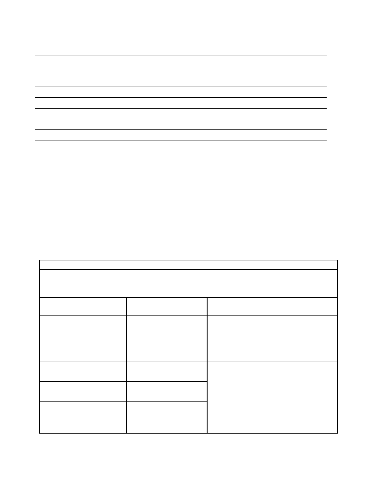
CE NOTICE
Marking by the symbol l indicates compliance of the Vitalograph
ALPHA to the Medical Devices Directive of the European Community.
Such marking is indicative that the Vitalograph ALPHA meets or
exceeds the following technical standards:
Guidance and manufacturer’s declaration – electromagnetic emissions
The ALPHA is intended for use in the electromagnetic environment specified below.
The customer or the user of ALPHA should assure that it is used in such an
environment.
Emissions test Compliance Electromagnetic environment –
guidance
RF emissions
CISPR 11
Group 1 The ALPHA uses RF energy only for
its internal function. Therefore, its RF
emissions are very low and are not
likely to cause any interference in
nearby electronic equipment.
RF emissions
CISPR 11
Class B
Harmonic emissions
IEC 61000-3-2
Class A
Voltage fluctuations/
flicker emissions
IEC 61000-3-3
Class A
The ALPHA is suitable for use in all
establishments, including domestic
establishments and those directly
connected to the public low-voltage
power supply network that supplies
buildings used for domestic
purposes.
25
Page 31

Guidance and manufacturer’s declaration – electromagnetic immunity
The ALPHA is intended for use in the electromagnetic environment specified
below. The customer or the user of the ALPHA should assure that it is used in
such an environment.
Immunity test IEC 60601
Test level
Compliance
level
Electromagnetic
environmentguidance
Electrostatic
discharge (ESD)
IEC 61000-4-2
±6 kV contact
±8 kV air
±6 kV contact
±8 kV air
Floors should be wood,
concrete or ceramic
tile. If floors are
covered with synthetic
material, the relative
humidity should be at
least 30%
Electrical fast
transient/burst
IEC 61000-4-4
±2 kV for power
supply lines
±1 kV for input/
output lines
±2 kV for
power supply
lines
Mains power quality
should be that of a
typical commercial or
hospital environment.
Surge
IEC 61000-4-5
±1kV differential
mode ±2kV
common mode
±1 kV
differential
mode
Mains power quality
should be that of a
typical commercial or
hospital environment.
Voltage dips,
short interruptions
and voltage
variations on
power supply
input lines
IEC 61000-4-11
<5 % 100V
(>95% dip in
100V) for 0,5
cycle
40 % 100V
(60% dip in
100V) for 5
cycles
70 % 100V
(30% dip in
100V) for25
cycles
<5% 100V
(>95% dip in
100V) for 5 sec
Performance
A
Performance
A
Performance
A
Performance
A
Mains power quality
should be that of a
typical commercial or
hospital environment.
If the user of the
ALPHA requires
continued operation
during power mains
interruptions, it is
recommended that the
ALPHA be powered
from an uninterruptible
power supply or a
battery.
Power frequency
(50/60 Hz)
magnetic field
IEC 61000-4-8
3 A/m Not
Applicable
Power frequency
magnetic fields should
be at levels
characteristic of a
typical location in a
typical commercial or
hospital environment.
26
Page 32
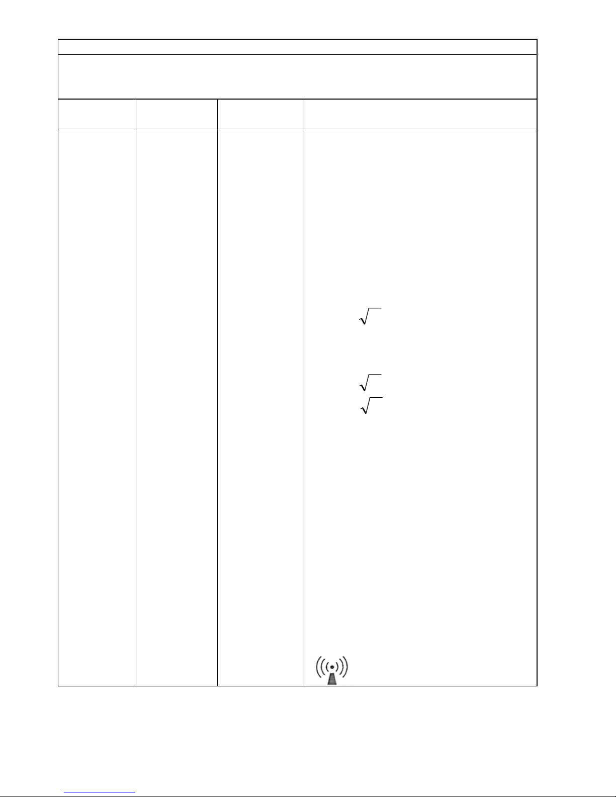
Guidance and manufacturer’s declaration – electromagnetic immunity
The ALPHA is intended for use in the electromagnetic environment specified
below. The customer or the user of the ALPHA should assure that it is used in
such an environment.
Immunity
test
IEC 60601
Test level
Compliance
level
Electromagnetic environment -
guidance
Conducted
RF IEC
61000-4-6
Radiated
RF IEC
61000-4-3
3 Vrms
150kHz to
80 MHz in
ISM bands
3 V/m
80 MHz to
2,5 GHz
3 Vrms
3V/m from
80MHz to
2.5 GHz
Portable and mobile RF
communications equipment should be
used no closer to any part of the
ALPHA including cables, than the
recommended separation distance
calculated form the equation
applicable to the frequency of the
transmitter.
Recommended separation distance
Pd 2.1=
Pd 2.1= 80MHz to 800MHz
Pd 3.2= 800MHz to 2.5GHz
Where P is the maximum output
power rating of the transmitter in watts
(W) according to the transmitter
manufacturer and d is the
recommended separation distance in
metres (m).
Field strengths from fixed RF
transmitters, as determined by an
electromagnetic site survey, should be
less than the compliance level in each
frequency range.
Interference may occur in the vicinity
of equipment marked with the
following symbol:
27
Page 33

Recommended separation distances between portable and mobile RF
communication equipment and the ALPHA
The ALPHA is intended for use in an electromagnetic environment in which
radiated RF disturbances are controlled. The customer or the user of the ALPHA
can help prevent electromagnetic interference by maintaining a minimum distance
between portable and mobile RF communications equipment (transmitters) and
the ALPHA as recommended below, according to the maximum output power of
the communications equipment.
Separation distance according to frequency of
transmitter
m
Rated maximum
output power of
transmitter
W
150 kHz to 80
MHz
d = 1.2√P
80 MHz to 800
MHz
d = 1.2√P
800 MHz to
2.5GHz
d = 2.3√P
0.01 0.1m 0.1m 0.2m
0.1 0.4m 0.4m 0.7m
1 1.2m 1.2m 2.3m
10 3.7m 3.7m 7.4m
100 11.7m 11.7m 23.3m
For transmitters rated at a maximum output power not listed above, the
recommended separation distance d in metres (m) can be estimated using the
equation applicable to the frequency of the transmitter, where P is the maximum
output power rating of the transmitter in watts (w) according to the transmitter
manufacturer.
NOTE 1 At 80 MHz and 800 MHz, the separation distance for the higher frequency
range applies.
NOTE 2 These guidelines may not apply in all situations. Electromagnetic
propagation is affected by absorption and reflection from structures, objects and
people.
Medical Devices may be affected by cellular telephones and other
personal or household devices not intended for medical facilities. It is
recommended that all equipment used near the Vitalograph product
comply with the medical electromagnetic compatibility standard and to
check before use that no interference is evident or possible. If
interference is suspected or possible, switching off the offending device
is the normal solution, as is required in aircraft and medical facilities.
Medical electrical equipment needs special precautions regarding EMC
and needs to be installed and put into service according to the EMC
information provided,
28
Page 34

Portable and mobile RF communications equipment can affect medical
electrical equipment.
FDA NOTICE
Caution: Federal Law restricts this device to sale by, or on the order of
a physician.
29
Page 35

DECLARATION OF CONFORMITY
Product:
Vitalograph alpha
Vitalograph hereby ensures and declares that the above product
associated with this user manual, is designed and manufactured in
accordance with the following QMS regulations and standards:
• European Medical Devices Directive {MDD}
93/42/EEC.
This device, classified as 2a as per Annex IX of MDD
93/42/EEC, meets the following provisions of Annex II
of the Medical Devices Directive as per Article 11,
section 3a, excluding point 4 of Annex II.
• Canadian Medical Device Regulation {CMDR}
• FDA Quality System Regulation {QSR} 21 CFR 820.
• EN ISO 13485: 2003. Medical devices. Quality management
systems. Requirements for regulatory purposes.
Certifying Body {for 93/42/EEC and CMDR}: British Standards Institute
{BSI}
Certificate Nos. CE 00772, MD 82182, FM 83550
Signed on behalf of Vitalograph (Ireland) Ltd.
B. R. Garbe.
Group Managing Director
30
Page 36

GUARANTEE
Subject to the conditions listed below, Vitalograph Ltd. and its
associated companies, (hereinafter called the Company) guarantee to
repair or at its opinion replace any component thereof, which, in the
opinion of the Company is faulty or below standard as a result of
inferior workmanship or materials.
The conditions of this Guarantee are:
1. This Guarantee shall only apply to hardware defects which are
notified to the Company or to its accredited distributor within 1 year
of the date of purchase of the equipment, unless otherwise agreed
in writing by the Company
2. Software (meaning computer software, or user installable modules)
is guaranteed for 90 days from the date of purchase.
3. The Company warrants that the software when correctly used in
conjunction with the hardware will perform in the manner described
in the Company's literature and user manuals. The Company
undertakes to rectify at no expense to the customer any software
failure notified within the period stated above, provided that the
failure can be recreated and the software has been installed and
used in accordance with the user manual. Notwithstanding this
clause, the software is not warranted to be free of errors.
4. This Guarantee does not cover any faults caused by accident,
misuse, neglect, tampering with the equipment, use of consumable
items or parts not approved by the Company, or any attempt at
adjustment or repair other than by personnel accredited by the
Company, nor does it cover reinstatement of any configuration
changes caused by the installation of any software.
5. If a defect occurs, please contact the supplier from whom it was
purchased for advice. The Company does not authorise any
person to create for it any other obligation or liability in connection
with Vitalograph equipment
6. This Guarantee is not transferable and no person, firm or company
has any authority to vary the terms or conditions of this Guarantee.
7. To the maximum extent permitted by law, the Company does not
accept liability for any consequential damages arising out of the
use of, or inability to use any Vitalograph equipment.
8. This Guarantee is offered as an additional benefit to the
Consumer’s statutory rights and does not affect these rights in any
way.
31
 Loading...