

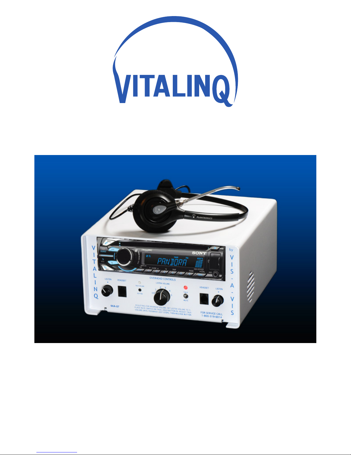
Vitalinq 94A-07 Operation And Installation Manual
TM
by VIS-A-VIS, INC.
7936 Camino Circle
Miami, FL 33143
support@vitalinq.com
(80 0) 319 -6014
Operations and Installation Manual
Vitalinq™ Communication System
Model 94A-07
CDX-GT575UP


Symbols and Conventions
This icon identifies cautions: information that should be
read before use to prevent damage to the Vitalinq™ system.
Trademark and Other Information
SiriusXM subscriptions and Satellite Radio Tuner are sold separately.
www.siriusxm.com.
Sirius, XM and all related marks and logos are trademarks of Sirius XM Radio Inc. and
its subsidiaries. All other marks and logos are the property of their respective owners. All
rights reserved.
ZAPPIN and Quick-BrowZer are trademarks of Sony Corporation.
Windows Media is either a registered trademark or trademark of Microsoft Corporation in the
United States and/or other countries.
This product contains technology subject to certain intellectual property rights of Microsoft.
Use or distribution of this technology outside of this product is prohibited without the
appropriate license(s) from Microsoft.
iPhone, iPod, iPod classic, iPod nano, and iPod touch are trademarks of Apple Inc., registered
in the U.S. and other countries.
VitalinqTM System Specifications
Input Ratings: 100-220V~
50-60Hz
1.6A MAX
Operating Temperature: 25˚C(77˚F)
Stereo Power Amplier Specications
Output: Speaker outputs
Speaker impedance: Only use with provided 8 ohm speakers
Maximum power output: 8W × 4 (with Vis-A-Vis provided 8 ohm speakers)
For Your Safety
1. Read these instructions.
2. Keep these instructions.
3. Heed all warnings.
4. Follow all instructions.
5. Do not use this apparatus near water.
6. Clean only with dry cloth.
7. Do not block any ventilation openings. Install in accordance with the
manufacturer’s instructions.
8. Do not install near any heat sources such as radiators, heat registers, stoves, or other
apparatus(includingampliers)thatproduceheat.
9. Do not defeat the safety purpose of the polarized or grounding-type plug. A polarized
plug has two blades with one wider than the other. A grounding type plug has two
blades and a third grounding prong. The wide blade or the third prong are provided for
yoursafety.Iftheprovidedplugdoesnottintoyouroutlet,consultanelectricianfor
replacement of the obsolete outlet.
10. Protect the power cord from being walked on or pinched particularly at plugs,
convenience receptacles, and the point where they exit from the apparatus.
11. Onlyuseattachments/accessoriesspeciedbythemanufacturer.
12. Useonlywiththecart,stand,tripod,bracket,ortablespeciedbythemanufacturer,or
sold with the apparatus. When a cart is used, use caution when moving the cart/
apparatus combination to avoid injury from tip-over.
13. Unplug this apparatus during lightning storms or when unused for long periods of time.
14. Referallservicingtoqualiedservicepersonnel.Servicingisrequiredwhenthe
apparatus has been damaged in any way, such as power-supply cord or plug is damaged,
liquid has been spilled or objects have fallen into the apparatus, the apparatus has been
exposed to rain or moisture, does not operate normally, or has been dropped.
15. Toreducetheriskofreorelectricshock,donotexposethisapparatustorain
or moisture.
16. A warning that excessive sound pressure from earphones and headphones can cause
hearing loss.

Table of Contents
1 VITALINQ™ INTRODUCTION 1
1.1 System layout 2
2 SETTING UP THE VITALINQ™ SYSTEM 3
2.1 Description of the VITALINQ™ system 3
2.2 Initial settings 3
2.3 Adjusting the headset 4
2.4 Adjusting the overhead controls 4
3 VITALINQ™ OPERATING INSTRUCTIONS 4
3.1 Initial operation of the headset 4
3.2 Operation of overhead speaker and desk
microphone 5
4 MUSIC SYSTEM OPERATION 6
4.1 Getting started 6
4.1.1 Music system power 6
4.2 Adjusting setup items 6
4.2.1 Canceling the DEMO mode 6
4.2.2 Setting the clock 6
4.2.3 Additional setup items 6
4.3 Location of controls and basic operations 9
4.4 Radio 11
4.4.1 Storing and receiving stations 11
4.4.2 RDS 11
4.5 CD 12
4.5.1 Playing a disc 12
4.6 USB devices 13
4.6.1 Playing back a USB device 13
4.7 iPod 13
4.7.1 Playing back iPod 14
4.7.2 Operating an iPod directly — Passenger control 15
4.8 Pandora® via USB (iPhone) 15
4.8.1 Streaming Pandora® 15
4.9 Searching and playing tracks 16
4.9.1 Playing tracks in various modes 16
4.9.2 Searching a track by name — Quick-BrowZer™ 17
4.9.3 Searching listening to track passages - ZAPPIN™ 18
4.10 Changing the illumination 19
4.10.1 Changing display and buttons
Dynamic Color Illuminator 19
4.10.2 Advanced color setting 20
4.11 Sound Settings and Setup Menu 20
4.11.1 Changing the sound settings 20
4.11.2 Customizing the equalizer curve — EQ7 Setting 22
4.12 Auxiliary audio equipment 23
4.12.1 Connecting the portable audio device 23
4.12.2 SiriusXM tuner 24
4.13 Additional Information 25
4.13.1 Notes on discs 25
4.13.2 PlaybackorderofMP3/WMA/AACles 26
4.13.3 About iPod 26
4.13.4 Safety precautions 27
5 TROUBLESHOOTING GUIDE 28
5.1 Most likely problems 28
5.2 Music troubleshooting guide 29
6 INSTALLATION 33
6.1 Planing the Vitalinq™ installation 33
6.1.1 Procedure room (LAB) 33
6.1.2 Control room (TEK) 33
6.1.3 Control room console 33
6.2 Installing Vitalinq™ speakers 35
6.2.1 Installing speakers in ceiling 35
6.3 Monitor Microphone Installation 37
6.3.1 Monitor microphone description 37
6.3.2 Monitor microphone placement 37
6.3.3 Monitor microphone cable connection 38
6.4 Installing the Vitalinq™ console 40
6.4.1 Front of Console 40
6.4.2 Rear of console 41
We would like to hear from you. Our phone number is 1-800-319-6014, or email us at support@vitalinq.
com. Please visit us on the web at http://www.vitalinq.com.
We are very interested in helping you to solve any problems or answer any questions you may have with the
operation or installation.
Please call and give us the name and address of the hospital, cath lab phone number and name of the cath
lab director or manager so that we can better serve them. This information can also be submitted via our
web site at www.vitalinq.com. Additionally, an electronic version of this manual can be obtained at our
web site.
Thank you for your help.
© Vis-A-Vis 2004-2014 Rev 08/27/2014


1 VITALINQ™ INTRODUCTION
Vitalinq™ is a communication system designed to
meetthespecicneedsthatariseduringdiagnostic
and interventional procedures. Vitalinq™ enables
physicians to have continuous two-way conversation
with control room operators throughout diagnostic
and catheterization procedures. Capable of picking
up conversation in a normal tone of voice, Vitalinq™
allows control room operators to respond immediately
to physicians requests. As vital signs are monitored by the control room operator, the physician
can receive up-to-the-moment communication on the patient’s condition.
The Vitalinq™ communication system provides speakers and microphones for the procedure
room (LAB) and control room (TEK). The speakers are mounted in the ceiling. Control room
operators have the option of using the overhead speaker and desk microphone, or a headset.
The procedure room microphone is attached to the video monitor (or monitor cluster) opposite
the physician, or optionally, integrated into the ceiling by replacing a standard ceiling tile.
The unique construction of our procedure room microphones contribute to Vitalinq’s high
intelligibility, even within the acoustically active space of a full-functioning lab. Designed to
minimize the loss of articulation by reducing the potential echo path, Vitalinq™ gathers and
transmitsspeechinahighlyefcientmanner.
by VIS-A-VIS, INC.
TM
Complete and comprehensive, the Vitalinq™ removes the need for talk-listen switching,
eliminating the risks posed by breaks in conversation. Physicians and control room operators
may converse without interruption.
Integrated into the console but operationally separate from the communication system is a
stereo system capable of playing music from a variety of sources. Sources include AM/FM
radio (subject to the limitations imposed by building shielding effects), compact discs and
musicfromexternaldevicessuchasasmartphone,satelliteradio,ashdriveoranydevice
capable of output to a mini-stereo or USB jack.
Westrivetoprovidethemostexiblesystemavailable.TolearnmoreaboutVitalinq’s
advanced capabilities, please contact us at 1-800-319-6014 or by email at info@vitalinq.com.
Advanced capabilities and options include:
• Wireless headset to replace corded headset
• Auxiliary wireless headsets are available for scrub or circulator nurses to provide discreet
communication with the control room operator.
• Remote connections for headsets & foot switches.
• Support for multiple headsets / desk microphones.
• Telephone interconnectability.
Contact us for details.
1
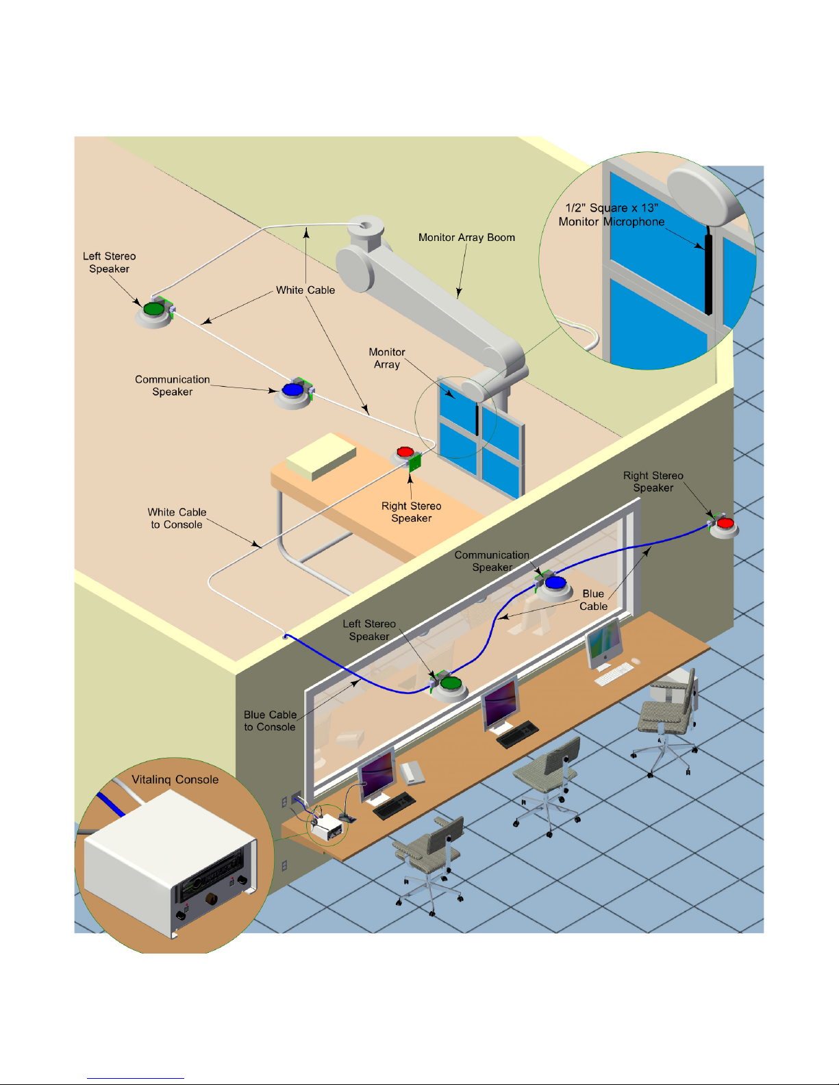
1.1 System layout
2

2 SETTING UP THE VITALINQ™ SYSTEM
2.1 Description of the VITALINQ™ system
Refer to Section 6 “INSTALLATION” for installation instructions.
The Vitalinq™ is very easy to use and versatile. The standard system is composed of a pair of
music speakers and a communication speaker in both the procedure and control rooms. The
speakers are mounted overhead in the ceiling. The procedure room also has a microphone
mountedtothemonitorarrayoppositethephysician.(Ifspecicallyrequestedwhenthe
system was purchased, you may have an overhead microphone in the ceiling instead of the
monitor microphone). The control room is where the console is located to which all devices
are ultimately connected. Also in the control room and plugged into the console, are a desk
microphone and a headset with foot switch. One desk microphone, headset and foot switch are
included with each system.
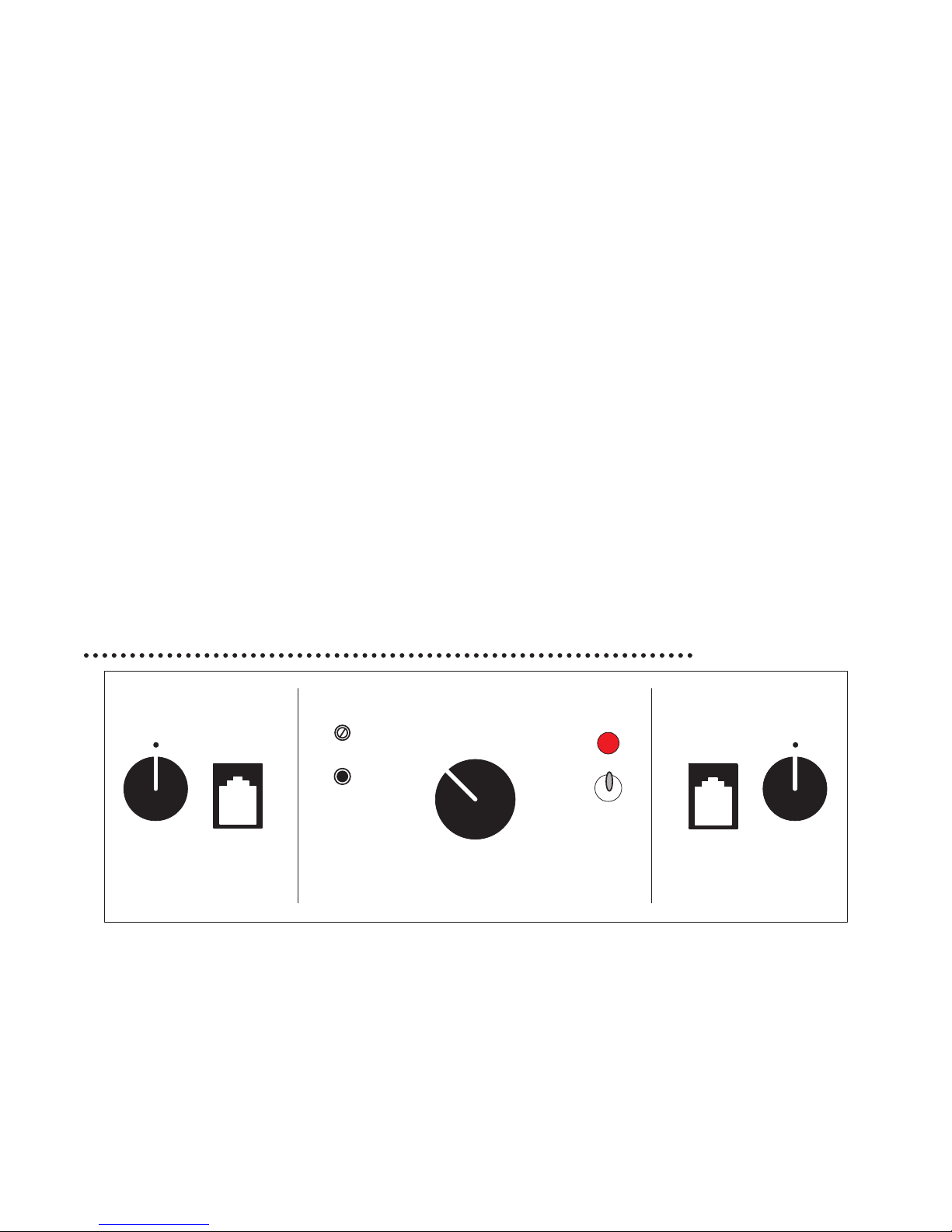
On the front of the console, divided between the top and bottom, are controls for the music
system and controls for talking and listening to the procedure room, respectively. At the rear of
the console are 1/4” jacks for foot switches and a thumbnail adjustable control for the headset
talk volume. Words in BLUE throughout this document refer to labels on the console.
The LISTEN control, FOOT SWITCH jack and HEADSET jack on each side of the console
work together. If a headset is plugged into the HEADSET jack on the left side of the console,
the foot switch for this headset needs to be plugged into the LEFT FOOT SWITCH jack on the
rear of the console. Conversely, if a headset is plugged into the HEADSET jack on the right
side of the console, the foot switch for this headset needs to be plugged into the RIGHT FOOT
SWITCH jack on the rear of the console. When depressed, the foot switch allows the headset
to transmit speech to the procedure room. Without a foot switch connected, the headset
constantly transmits sound to the procedure room.
The volume of the headset earpiece is adjusted using the LISTEN volume control located
adjacent to the HEADSET jack. The volume for the procedure room communication speaker
(used to transmit speech from the control room) is controlled by the HEADSET TALK
VOLUME switch located on the rear of the console.
The OVER HEAD CONT ROLS, at the bottom center of the console, are for the desk
microphone and speaker in the control room. In the OVER HEAD CONTROLS section are
a TALK switch and an overhead LISTEN VOLUME control. The BUTTON and TALK
VOLUME are only used for setup.
The TALK /MUTE switch on the console should always be in the TALK position when using
a desk mic, and the LED will be RED. The TALK /MUTE switch and its associated LED are
used primarily with a Control room pyramid microphone (optional equipment), which has no
other switch. In this situation, when the LED is RED the people in the procedure room can
hear you. With the TALK/M UTE in MUTE, the LED will be GREEN and the Control room
mic is off.
3
2.2 Initial settings
Tur n LISTEN controls to the 12:00 position. LISTEN VOLUME control OFF. Plug power
cord into 120 volt AC outlet. Set the TALK / MUTE switch to TALK. The LED above talk switch
should be RED.
2.3 Adjusting the headset
Put on headset and listen to person in procedure room. LISTEN controls what you hear.
HEA DSET TALK, on rear of console controls volume that procedure room hears. The headset
microphone tube telescopes. Move microphone tube tip close to the corner of your mouth.
Pressing foot switch allows you to talk and listen simultaneously to procedure room.
2.4 Adjusting the overhead controls
Unplug the headset. The OVERH EA D controls are at the lower front of the console between
the HEADSET jacks. Turn the LISTEN VOLUME switch to 3 and listen to the Lab. You
should be able to hear background noise. Lock the desk mic in the talk position by depressing
the LOCK button on the microphone base. The blue lamp behind the LOCK button will
illuminate. Turn the TALK VOLU ME control clockwise while pressing the BUTTON until
you just barely hear feedback squeal. Release the BUTTON. The TALK volume level is now
set. As you switch the LISTEN VOLUME louder or softer, the sound in the Lab varies by
aninverseamounttopreventfeedback.Whennished,besuretounlockthemicrophoneby
pressing the LOCK button again. The blue lamp will go out.
3 VITALINQ™ OPERATING INSTRUCTIONS
OVERHEAD CONTROLS
LISTEN VOLUME
TALK VOLUME
OFF
94A-07
BUTTON
ADJUSTING FOR MAXIMUM VOLUME SET LISTEN VOLUME TO 3,
PLACE MUTE SWITCH ON TALK, HOLD BUTTON IN, ADJUST TALK
VOLUME UNTIL FEEDBACK JUST STOPS, THEN RELEASE BUTTON.
3.1 Initial operation of the headset
BLUE words are labels on console. Place the TALK switch on MUTE and the LISTEN
VOLUME control at OFF. Turn the headset LISTEN control to the middle of its rotation. The
headset is easy to adjust. The headband slides in and out of the ear-cup. Put the headset on. The
headset microphone tube telescopes. Move it so that the microphone tube tip is near the corner of
your mouth. Listen to someone in the procedure room.
2
3
1
4
5
TALK
MUTE
LISTENHEADSET
LISTENHEADSETLISTEN HEADSET
FOR SERVICE CALL
1-800-319-6014
4
Pressing the foot switch allows you to talk via the headset, to people in the procedure room.
You will hear the people in the procedure room whether the foot switch is pressed or not. Not
pressing the footswitch will mute your voice. Unplugging the foot switch un-mutes the headset
microphone. Adjust the headset LISTEN volume for a comfortable level by means of the volume
control labeled LISTEN. The left headset LISTEN volume control is for a headset plugged into
the left jack and the right one controls the right jack. The foot switches control the same side
jack. The white slotted shaft on the rear by the left footswitch jack labelled HEADSET TALK
controls both of the headsets talk volume.
3.2 Operation of overhead speaker and desk microphone
Adjust the LISTEN VOLUME control to a comfortable level for people in the control room.
To talk to the procedure room without using the headset, place the TALK switch in the TALK
position. The GREEN light will turn RED. The desk mic has a push to talk switch on its base.
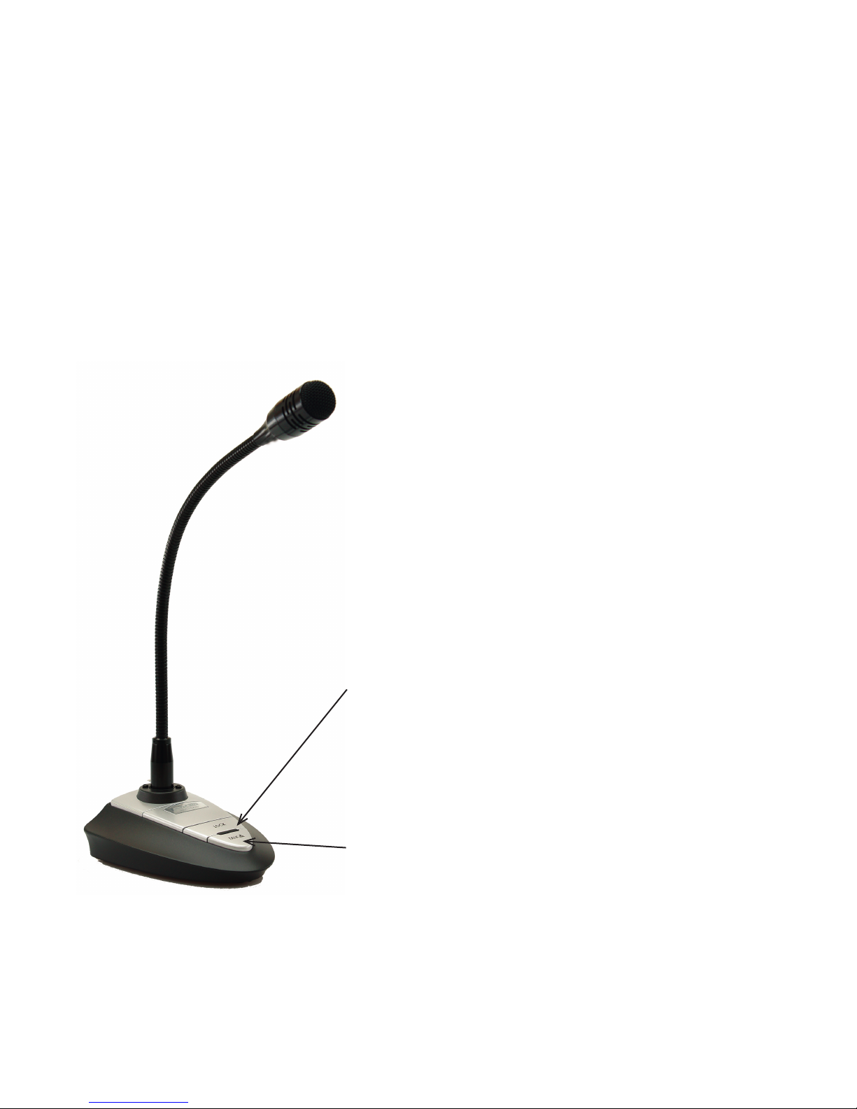
If desired, the microphone may be locked in the always on mode
by pressing the LOCK button on the microphone base. There
is a blue light behind the button that lights up to show that it
is locked on. To release the always on mode, press the LOCK
button again. There is a blue light behind the button that lights
up to show that it is locked on.
If the TALK VOLUM E control is turned too far clockwise, you
will hear a hum or squeal; turn it down using your thumbnail
or small screwdriver, as described in Section 2.5. It is normal
to have to speak louder when using the overhead TALK
position. When not in use leave the TALK switch in MUTE.
The talk volume may be adjusted by following the directions on
the console.
To lock the microphone in the “always
on” position, press the “Lock” button.
To unlock, press the “Lock” button
again. A blue light behind the button
is illuminated when the microphone is
locked on.
The “Talk” button is used for normal Push-To-Talk operation.
5

4 MUSIC SYSTEM OPERATION
4.1 Getting started
4.1.1 Music system power
button
1 Press to turn on the power/change the source (Radio/CD/USB/AUX).
2 Press for 1 second to turn off the power.
3 Press for more than 2 seconds to turn off the power and display.
4.2 Adjusting setup items
4.2.1 Canceling the DEMO mode
You can cancel the demonstration display which appears while this unit is turned off.
1 Press , rotate the control dial until “DISPLAY” appears, then press it.
2 Rotate the control dial until “DEMO” appears, then press it.
3 Rotate the control dial to select “DEMO-OFF,” then press it.
The setting is complete.
4 Press O(BACK) twice.
The display returns to normal reception/ play mode.
4.2.2 Setting the clock
The clock uses a 12-hour digital indication.
1 Press , rotate the control dial until “GENERAL” appears, then press it.
2 Rotate the control dial until “CLOCKADJ” appears, then press it.
Thehourindicationashes.
3 Rotate the control dial to set the hour and minute.
To move the digital indication, press +/–.
4 After setting the minute, press .
The setup is complete and the clock starts.
To display the clock, press .
4.2.3 Additional setup items
1 Press , rotate the control dial until the desired category appears, then
press it.
2 Rotate the control dial until the desired item appears, then press it.
3 Rotate the control dial to select the setting, then press it.*
The setting is complete.
4 Press O (BACK) to return to the previous display.
6
* For CLOCK-ADJ and BTM settings, step 4 is not necessary.

The following items can be set depending on the source and setting:
GENERAL:
SOUND:
CLOCK-ADJ (Clock Adjust)
CAUT ALM*1 - NOT USED
BEEP
Activates the beep sound: “ON,” “OFF.”
AUTO OFF
Shuts off automatically after a desired time when
the unit is turned off: “NO,” “30S (Seconds),” “30M
(Minutes),” “60M (Mi nutes).”
AUX-A*1 (AUX Audio)
Activates the AUX source display: “ON,” “OFF”.
REAR/SUB- NOT USED
CT (Clock Time)
Activates the CT function: “ON,” “OFF”
BTM
ZAPPIN
*3
ZAP TIME (Zappin Time)
Selects the playback time for the ZAPPIN function.
• “Z.TIME-1 (about 6 seconds),”
• “Z.TIME-2 (about 15 seconds),”
• “Z.TIME-3 (about 30 seconds).”
ZAP BEEP (Zappin Beep)
Applies a beep sound between track passages:
“ON,” “OFF.”
PARENTAL
*4
Sets the parental lock to “ON” or “OFF,” and
edits the passcode.
EQ7 PRESET
EQ7 SETTING
POSITION- NOT USED
BALANCE
Adjusts the sound balance: “RIGHT-15”–
“CENTER” – “LEFT-15.”
FADER
Adjusts the relative level between rooms:
“FRONT-15” – “CENTER” – “REAR-15.”
*3
DM+
LOUDNESS (Dynamic Loudness)
Reinforces bass and treble for clear sound at low
volume levels: “ON,” “OFF.”
ALO (Automatic Level Optimizer)
Adjust the playback volume level of all playback
sources to the optimum level: “ON,” “OFF.”
RB ENH
*4
- NOT USED
SW DIREC*5- NOT USED
S.WOOFER
*2
(Subwoofer) - NOT USED
HPF (High Pass Filter) - NOT USED
AUX VOL
*6
(AUX Volume Level)
Adjusts the volume level for each connected
auxiliary equipment: “+18dB” – “0 dB” – “-8 dB.”
This setting negates the need to adjust the volume
level between sources.
*1 When the unit is turned off.
*2 When the tuner is selected.
*3 When the CD or USB is selected.
*4 When the SiriusXM Connect tuner is connected.
*1 Does not appear when “SET F/R POS” is set to “OFF”.
*2 When the audio output is set to “SUB-OUT”.
*3 Does not appear when the tuner is selected.
*4 When the audio output is set to “REAR-OUT” and
“SW DIREC” is set to “OFF”.
*5 When the audio output is set to “REAR-OUT” and
“RBE MODE” is seet to “OFF”.
*6 When the AUX is selected.
7

DISPL AY:
DEMO (Demonstration)
Activates the demonstration: “ON,” “OFF.”
DIMMER
Changes the display brightness.
• “AT” - NOT USED
• “ON”: to dim the display.
• “OFF”: deactivate the dimmer.
COLOR (Preset Color)
Selects the preset color of the display and buttons
on the main unit.
CUSTOM-C (Custom Color)
Selects a preset color as a basis for further
customizing.
SND SYNC
Selects the color with sound synchronization:
“ON,” “OFF.”
WHT MENU
Sets the effect when the source is switched: “ON,”
“OF F.”
START-W H T
Sets the start up color: “ON,” “OFF.”
AUTO SCR* (Auto Scroll)
Scrolls long items automatically: “ON,” “OFF.”
M.DISPLAY (Motion Display)
“SA”: to show moving patterns and spectrum
analyzer.
“OFF”: to deactivate the Motion Display.
LPF FREQ*2 - NOT USED
LPF SLOP*2 - NOT USED
SW PHASE*3 - NOT USED
HPF FREQ (High Pass Filter Frequency)
Selects the front/rear speaker cut-off frequency:
“OFF,” “50Hz,”“60Hz,” “80Hz,” “100Hz,” “120Hz.”
HPF SLOP (High Pass Filter Slope)
Selects the HPF slope (effective only when HPF
FREQ is set to other than “OFF”): “1,” “2,” “3.”
*When the CD or USB is selected.
8
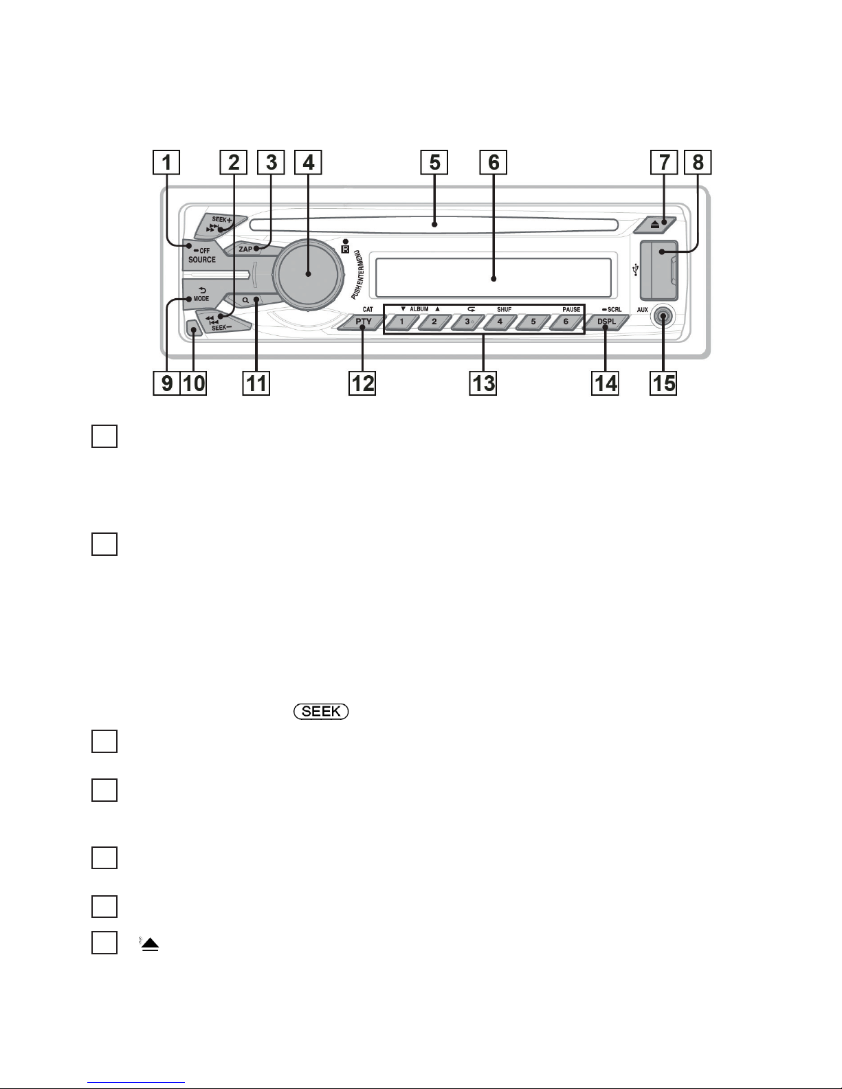
4.3 Location of controls and basic operations
This section contains instructions on the location of controls and basic operations.
1
SOURCE/OFF button
*1
Press to turn on the power; select the source (Radio/CD/USB/Pandora® USB /AUX ).
Press repeatedly to change to another source.
Press and hold for 1 second to turn off the power.
Press and hold for more than 2 seconds to turn off the power and the display disappears.
2
SEEK +/– buttons
Radio:
Totuneinstationsautomatically(press);ndastationmanually(pressandhold).
CD/USB:
To skip tracks (press); skip tracks continuously (press, then press again within about 2 seconds
and hold); reverse/fast-forward a track (press and hold).
Pandora® via USB:
To skip a track (press+) .
3
ZAP button
To enter ZAPPIN™ mode.
4
Control dial/ENTER/MENU button
Rotate to adjust volume.
Press to enter setup mode.
5
Disc slot
Insert the disc (label side up), playback starts.
6
Display window
7
(eject) button
To eject the disc.
9
 Loading...