

Vital Home Systems VHS-1060 User Manual

Wireless Control Panel Manual
Vital Home Systems
TM
Wireless Control Panel
Model: VHS-1060
Manual V 6.0 Dated 10/09/2016
© Copyright 2016 Vital Home Systems

Table of Contents
Wireless Control Panel Control Panel Overview ........................................................................2
I. Identifying Parts on the Wireless Control Panel ............................................................... 2
II. The Power Supply .............................................................................................................. 3
III. How to Install the Wireless Control Panel ....................................................................... 3
V. Getting Started ................................................................ .................................................. 3
Programming the Wireless Control Panel ...................................................................................3
P a g e | 1
Wireless Control Panel Local Programming Quick Reference Chart ......................................3
How to Use Programming Mode .................................................................................................3
To Enter Programming Mode ......................................................................................................4
Storing Phone Numbers ........................................................................................................ 4
Changing Phone Numbers .................................................................................................... 4
Clear Phone Numbers ........................................................................................................... 4
Range Testing ........................................................................................................................ 4
Exit Programming Mode ........................................................................................................ 5
Reset Wireless Control Panel to Default Settings ............................................................... 5
Operation ............................................................................................................................... 5
Fault Situations ...................................................................................................................... 5
FCC Compliance Statement..........................................................................................................6
LED CONDITION – QUICK REFERENCE..............................................................................7
Sensor and Valve Zones.................................................................................................................8
Vital Home Systems Limited Warranty ......................................................................................9
© 2015 - 2016 Vital Home Systems, LLC
P a g e | 2
© 2015 - 2016 Vital Home Systems, LLC
1
3
Wireless Control Panel
Overview Model: VHS-1060
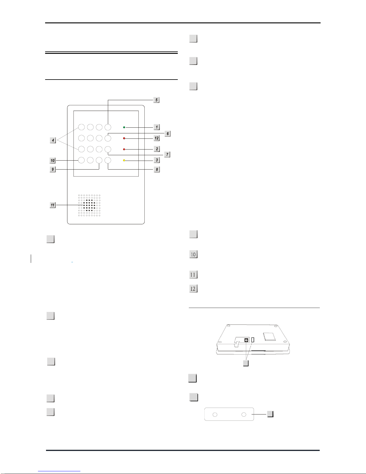
I. Identifying Parts on the Wireless
Control Panel
FRONT VIEW
Green/Red LED – Power Indicator
Green indicates the Power Status.
Green LED ON indicates Power ON.
Green LED flash indicates AC failure.
RED indicates Program / Learn / Range Test
Mode.
Red LED ON indicates Program / Learn Mode.
Red LED flash indicates Range Test Mode.
Green – Cellular Signal Indicator
LED OFF indicates not connected to Cellular
network.
Green LED ON indicates Wireless Control Panel
connected to cellular network
Yellow LED – Fault Indicator
The Yellow LED will light up when any fault
situation is detected, then turn off when all
fault conditions are restored.
NUMERIC KEY
SET KEY
Press this key for setting the telephone
numbers.
CLR KEY
Press this key to exit Program Mode and return
to Normal Mode.
7
TEST KEY
While in Program Mode, press this key to enter
TEST Mode.
8
ACK KEY
Press this key to stop the voice Alarm after
alarm is sounded and it will stop the SMS from
going out if pressed prior to voice alarm. This
key may also be used for deleting a digit,
canceling the selection, aborting the current
application and returning to the Normal Mode,
etc.
It may also be used to stop playing the local
voice message.
When there is Fault situation indicated by
Yellow LED ON, pressing “ACK” will play the
corresponding voice message for 30
seconds or till CLR is pressed.
When there is no Fault, pressing “ACK” will
give no response.
# KEY
Press this key to dial #
KEY
Press this key to delay dial for three (3) seconds
Speaker
SMS LED – Flashes Red when sending SMS from
Wireless Control Panel
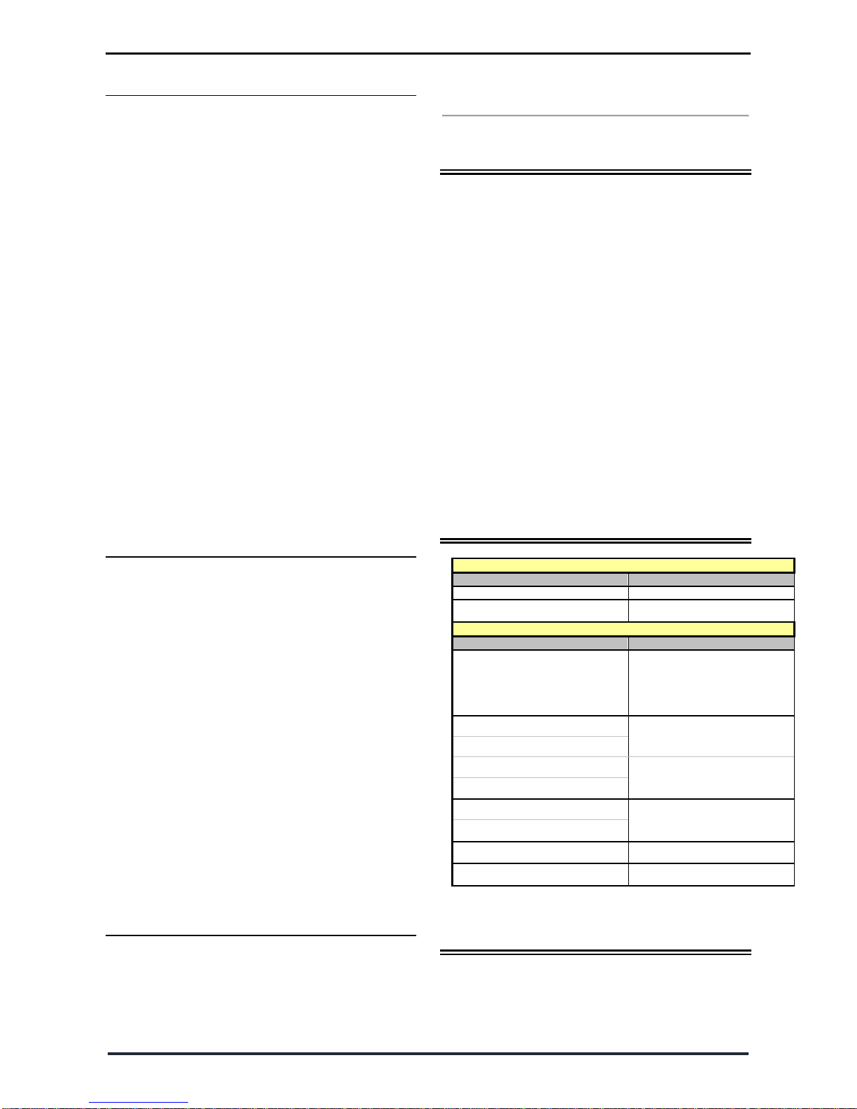
Side and Rear Views
Power – 5V Micro USB Jack and Battery Switch
DC 5V Micro USB and Battery Switch cover.
Wall Mounting Bracket
4
5
6
8
9
2
1
2
3
4
5
6
7
8
9
0
*
#
SET
CLR
TEST
ACK
13
13
14
14
P a g e | 3
© 2015 - 2016 Vital Home Systems, LLC
II. The Power Supply
An AC power adapter is required to connect to a
wall outlet. Only use the supplied DC 5V output and
micro USB adapter with the Wireless Control Panel
control panel.
Activating Rechargeable Backup Battery
In addition to the adapter, an internal
rechargeable battery in the Control Panel will
serve as a backup in case of a power failure.
During normal operation, the AC power
adapter supplies power to the Control Panel
and recharges the battery with the battery
switch in the ON postion
To charge the battery and have the battery
supply backup power in the event of a power
loss, remove the rubber battery switch cover
and slide the battery switch to “ON” with a
When the battery is fully charged, it can
provide back-up power for a period of at least
7 hours of standby time: It takes
approximately 48 hours to fully charge the
battery.
III. How to Install the Wireless Control
Panel
The easiest way to get to know the system and get
it up and running quickly is to place all the devices
and accessories programmed on a tabletop before
locating and mounting them.
The Wireless Control Panel can be mounted on the
wall or wherever desired. Make sure that the
Wireless Control Panel is positioned at
approximately chest height, so that the display may
be easily seen and the keypad will be convenient to
operate.
Using the Wall Mounting Bracket as a
template, mark the positions of the two (2)
holes.
Drill the holes, then install the screws and
dowels provided.
Place the Wireless Control Panel unit onto the
Wall Mounting Bracket, with the front facing
towards you.
V. Getting Started
Power supplied by an external 5V DC power
adaptor: Two (2) beeps are emitted and the Power
LED Green flashes ON indicating that it has entered
Normal Mode.
Continue to program the unit as instructed in next
section.
Programming the Wireless
Control Panel
All programming and pairing of devices with the
Wireless Control Panel control panel sensors and
VC100 valve controller may be done the Vital Home
Systems PC software. The software may be
downloaded from Vital Home Systems Website at:
http://www.vitalhomesystems.com/#!resources/c9ds
You must register your Wireless Control Panel on the
Vital Home Systems Website to download the
software.
The Software is written only for Windows version 7
through Vista. Download and install the software to
your Windows Desktop prior to plugging the
Wireless Control Panel USB cable into the computer
and the Wireless Control Panel Control Panel. Please
see the software manual for programming
Wireless Control Panel
Local Programming Quick
Reference Chart
Wireless Control Panel in Normal mode Commands
Function
Keypad operation
Enter program mode
SET + # + (pin code) + SET
Clearing alarms
ACK Key
Commands while in Wireless Control Panel Program mode
Function
Keypad operation
Set phone number
SET + (1~10) + # + (phone
number) + SET
Clear phone number
SET + (1~10) + SET
Test phone number
TEST + (1~10) + SET
Cold Water Valve ID(01~64) close
SET + 20 + # + (1~64) + SET
Hot Water Valve ID(01~64) close
SET + 20 + # + (1~64) + * + SET
Cold Water Valve ID(01~64) open
SET + 21 + # + (1~64) + SET
Hot Water Valve ID(01~64) open
SET + 21 + # + (1~64) + * + SET
Disable Auto Water Shutoff feature
SET + 30 + SET
Enable Auto Water Shutoff feature
SET + 31 + SET
Water sensor & Valve Range Test
TEST + 80 + SET
Pin code (passcode) change
SET + 90 + # + (pin code) + SET
How to Use
Programming Mode
The Wireless Control Panel may also be programmed
for certain functions locally on the control panel
face. See the next section how to program the
Wireless Control Panel locally.
 Loading...