


Vitalab Flexor E Service manual

Vitalab Flexor E Service Manual
Vitalab Flexor E Service Manual 6002 - 190 - 450
date of release: 1 February 2000
version: 1
______________________________________________________________________________________________
VITAL SCIENTIFIC N.V. Service Manual

Vitalab Flexor E Service Manual
Preface
The contents of this manual with all figures, tables and graphic representations are intellectual property of
Vital Scientific N.V. Unauthorised commercial or non-commercial excerption or copying of contents and
use of this manual (ion total or in parts) are strictly forbidden unless the editor gives written permission for
it.
This manual was written and reproduced with the utmost care. However, errors cannot be fully excluded.
Vital Scientific N.V. does not take any responsibilities and accepts no liabilities for incidents of any kind
that may occur because of errors in the manual.
All products names that are mentioned in this manual are registered trademarks.
The manual describes the analyser system Vitalab Flexor E.
The Vitalab Flexor E was conceptualised, manufactured and tested in accordance with the declaration of
conformity. The declaration of conformity is supplied with each device in a separate file.
Vital Scientific N.V.
P.O. Box 100, 6950 AC Dieren
Van Rensselaerweg 4, 6956 AV Spankeren
The Netherlands
++31 313 430 500
This manual was conceptualized, written and layouted by Vital Scientific N.V.
______________________________________________________________________________________________
Service Manual VITAL SCIENTIFIC N.V.

SERVICE MANUAL 1. GENERAL
1 GENERAL
1.1 INTRODUCTION
The instrument has been designed as a fully selective Patient Orientated Analyser
system. The chemistries include kinetic, two-point and endpoint determinations with
both linear and non-linear calculation modes.
The instrument has two modes: mono mode for running mono reagents and dual
mode for dual reagents. The mono-reagent mode has a maximum throughput of 180
tests/hour. The dual-reagent mode has a maximum throughput of 133 tests/hour.
1.2 SCOPE AND ORGANIZATION
This Service Manual is part of a two-volume set.
The Instruction Manual is the first part of this set.
The Instruction manual provides detailed operating instructions, technical
specifications and some brief trouble shooting in structions.
The Service manual has been prepared for service technicians and other technical
personnel directly involved in maintaining and repairing the instrument.
The reference information is provided in 10 separate sections.
Section 1: General
This section provides general information about the service and repair policy,
warranty, spare parts, technical assistance and service trainings.
Section 2: Functional design
This section provides information about the functional design of the analyser.
This includes a short description of the functional units like sample rotor, washing
unit, monitor etc., a description of the mechanical and optical design, and the fluid
system.
Section 3: System organisation
This section describes the system organisation of the instrument that includes the
theory of operation and the design of the different electron ic circuits.
Section 4: Installation & Main ten ance
This section provides instructions for installation and maintenance of the instrument,
and test diagnostics.
VIT AL SC IE NT IFIC 1.1

1. GENERAL SERVICE MANUAL
Section 5: Mechan ical adju stm ents
This section describes the procedures for mechanical adjustments.
The assembly/disassembly instructions are included as well.
Section 6: Electr ical adju stments
This section describes the electrical adjustment procedures.
Section 7: Error handling
This section contains the error handling and a comprehensive procedure for trouble
shooting. A consolidated list of necessary support equipment can also be found in
this chapter.
Section 8: Electr ical diagrams
This section provides all the relevant electrical diagrams, PCB assemblies, electrical
component part lists and wiring diagrams.
Section 9: Mechan ical drawin gs
This section provides the mechanical d rawing s, part lis ts , and facilitates the
identification and ordering of service parts.
Section 10:
This section is initially left blank but is meant for service information regarding the
analyser.
1.3 REPAIR POLICY
Refer to the section “General conditions of sale” in the Price List for the general
repair policy.
1.4 WARRANTY
Refer to the section “General Conditions of Sale” in the Price List for the general
warranty policy.
1.5 SPARE PARTS
Refer t o the section “General Conditions o f Sale” in the Pri ce List for the general
spare parts policy.
1.2 VITAL S CIEN TIFIC

SERVICE MANUAL 1. GENERAL
1.6 TECHNICAL ASSISTANCE
Should you encounter a problem that requires technical assistance, you may call, fax
or email the Service Department of Vital Scientific.
Please be prepared to give a clear and complete description of the problem.
Also be prepared to give an answer to the following questions:
• type of instrument
• serial number
• software version (when applicable)
• revision level (in case of a PCB)
1.7 SERVICE TRAINING
Service training courses are organised on a regular base. Information is available
from the Sales department of Vital Scientific. In principal courses will be held at Vital
Scientific, but in consultation it is possible to organise a course at the customers site.
Participants are expected to have knowledge of:
• analog / digital electronics
• microprocessor techniques
• basic photometric techniques
• the English language
Please contact the Service Department of Vital Scientific for information about
service trainings.
1.8 FIELD SERVICE INFORMATION
The purpose of the Fi el d Service Information system is to provide detailed
information on the frequency and nature of failures that occur during field use.
This information enables us to take corrective actions and to improve on the design
and manufacturing methods.
For this purpose we have designed two different forms:
• Installation report
• Malfunctioning report
The Installation report should be filled-out when the instrument is installed at the
customers’ site.
The malfunctioning report should be filled-out each time when a service action is
performed on the instrument.
We request you to return the filled-out forms to us on a regular base (for example
once a month) by mail or fax, whatever is convenient.
VIT AL SC IE NT IFIC 1.3

The contents of this manual with all figures, tables and graphics are intellectual property of Vital
Scientific.
Unauthorized commercial or non-commercial excerption or copying of contents and use of this manual
(in total or in parts) are strictly forbidden unless the editor gives written permission for it.
This manual was written and produced with the utmost care. However, errors cannot be fully excluded.
Vital Scientific does not take any responsibility and accepts no liabilities for incidents of any kind that
may occur because of errors in the manual.
All product names that are mentioned in this manual are registered trademarks. The manual describes
the analyser system Fibron Ι and its software version 1.0 (November 2002).
The Fibron Ι is conceptualised, manufactured and tested in accordance with the declaration of
conformity. The declaration is supplied with each device in a separate file.
Please call your local distributor if you need advice or you have any questions.
Article No: 6002-500-450
Van Rensselaerweg 4
6956 AV Spankeren, The Netherlands
Phone: +31-3134-30500
Fax: +31-3134-27807
email: service@vital.nl


TABLE OF CONTENTS
SAFETY PRECAUTIONS AND POTENTIAL HAZARDS _______________________________ 2
GENERAL_________________________________________________________________ 2
PERATOR QUALIFICATIONS___________________________________________________ 2
O
S
ERVICE TECHNICIAN QUALIFICATIONS ___________________________________________ 2
ESCRIPTION OF SYMBOLS____________________________________________________ 2
D
E
LECTRICAL_______________________________________________________________ 3
ECHANICAL ______________________________________________________________ 3
M
C
HEMICAL ________________________________________________________________ 3
B
IOHAZARDOUS MATERIALS ___________________________________________________ 3
S
AMPLES_________________________________________________________________ 3
W
ASTE SOLUTION AND SOLID WASTES ___________________________________________ 4
B
IOHAZARDOUS PARTS_______________________________________________________ 4
DDITIONAL PRECAUTIONS ____________________________________________________ 4
A
F
LAMMABLES ______________________________________________________________ 4
A
CCURACY/PRECISION OF MEASURED RESULTS ____________________________________ 4
A
PPLICATION ______________________________________________________________ 4
NSTALLATION REQUIREMENTS _________________________________________________ 5
I
NSTRUMENT UNUSED FOR A LONG PERIOD OF TIME _________________________________ 5
I
ERROR HANDLING____________________________________________________________ 6
PARTS-OVERVIEW____________________________________________________________ 8
PARTS LIST_________________________________________________________________ 10
Fibron-1 Manual/Vital Scientific NV / Service manual Rev 1.0 Page 1

Safety precautions and Potential hazards
General
Before you start installing and working with the analyser, you should read the safety
precautions and regulations detailed in this chapter. Safety comes first!
Operator Qualifications
− Operation should be conducted under the management of a
technician/operator who has undergone training at the facility specified by
the sales agent.
− For clinical tests, the instrument should be used under the management of
a doctor or clinical inspector.
Service Technician Qualifications
To install, maintain and repair the instrument, a service technician has to be trained
in the use of the instrument b y the manufacturer or their representative. A service
technician is also expected to be familiar with the normal and special operations of
the instrument as described in this User’s Manual.
Description of Symbols
This means that the labelled item could lead to personal injury and/or damage to the
analyser.
Note:
Notes contain additional information corresponding to the text.
Fibron-1 Manual/Vital Scientific NV / Service manual Rev 1.0 Page 2

Electrical
Please pay attention to the following items:
• To prevent the risk of electrical shock and/or damage to the instrument
Operators should not open the top cover of the instrument. Only authorised
personnel, for example, service technicians, may open the instrument to
perform maintenance or repair.
• Don't touch the main board when the power is on as this may cause severe injury
or death.
Mechanical
There is no risk presented by the mechanical parts of the instrument when the covers
are closed. If the covers of the instrument are removed, mechanical parts could
cause personal injury if touched or become damaged. Therefore, the following advice
must be followed: DO NOT wear loose garments or jewelry that could catch in
mechanisms. DO NOT put your fingers/ hands into the path of any part while the
analyzer is in operation. DO NOT attempt to make mechanical repairs unless the
instrument is not in operation or turned OFF.
Chemical
The operator is responsible for taking all necessary precautions against hazards
associated with the use of clinical laboratory chemicals. Specific recommendations
for each reagent used with the analyser are normally found on the manufacturer's
package inserts or on product information sheets for each chemical. W ipe away any
reagent spillage on the instrument immediately.
Biohazardous Materials
As with all in vitro diagnostic equipment, patient samples and serum-based quality
control (QC) products that are assayed on this system, as well as all waste from the
waste container, should be treated as potentially biohazardous. All materials and
mechanical components associated with the sampling and waste system should be
handled according to your facility's biohazard procedure. Use the personal protective
equipment recommended by your facility when handling any of these components.
Detailed recommendations:
Samples
Treat all samples as potentially biohazardous and infectious. If any sample is spilt on
the instrument, utilise the correct personal protective equipment (PPE-gloves, lab
coat, etc.), wipe it away immediately and clean the contaminated surface with a
disinfectant.
Fibron-1 Manual/Vital Scientific NV / Service manual Rev 1.0 Page 3

Waste Solution and Solid Wastes
• Avoid direct contact with waste solution and/or solid waste. Both should be
handled as potentially biohazardous.
• Dispose of waste solution and/or solid waste according to the relevant
governmental regulations.
• Consult the reagent manufacturer for information on the concentrations of heavy
metals and other toxic constituents in each reagent.
Biohazardous Parts
• Avoid direct contact with all parts of the sample-area. Treat these
areas as potentially biohazardous and/or infectious.
• Avoid direct body-contact with reagents. Direct body-contact may result in
irritation or damage to your skin. Refer to the manufacturer's reagent kit box and
package inserts, or product information sheets for specific instructions.
• Avoid direct body-contact with cleaning solutions. Direct body-contact may result
in skin irritation or damage. Refer to the manufacturers kit box and package
inserts, or product information sheets for specific instructions.
Additional precautions
Flammables
Avoid using dangerous flammable material around the instrument. Fire or explosion
may be caused by ignition.
Accuracy/Precision of Measured Results
• For proper use of the instrument, measure control samples and monitor the
instrument during operation.
• An incorrectly measured result may lead to an error in diagnosis, thereby posing a
danger to the patient.
• Treat all reagents according the manufacturer's recommendations. Refer to the
reagent kit box and package inserts, or product information sheets for specific
instructions.
Application
• The Fibron-1 is a single channel coagulometer that works on the principle of
photometric clot detection. The detection of the coagulation end point is achieved
by measuring the change in optical density of a plasma/reagent sample.
• Please note that other types of analyses may not be applicable to this instrument.
Fibron-1 Manual/Vital Scientific NV / Service manual Rev 1.0 Page 4

• Operation and Maintenance of the analyser should be performed in accordance
with the instructions in this manual.
• During operation and maintenance of the instrument, proceed according to the
instructions and do not touch any parts of the instrument other than those
specified.
• Always clean the instrument after a batch of measurements
• Ensure that both the covers are closed when the instrument is in operation.
• Avoid touching the instrument inside while the instrument is operating. This may
cause operation to stopped or damage the instrument.
Installation Requirements
Installation should only be performed by a representative of the instrument's
manufacturer. The customer is responsible for providing the necessary facilities as
detailed in chapter "Technical Data" in this User’s Manual
Instrument Unused for a Long Period of Time
If the instrument is not due to be used for a long period of time, ensure that it is
thoroughly cleaned . Place the dustcover over the analyzer to prevent dust from
entering the analyzer.
Fibron-1 Manual/Vital Scientific NV / Service manual Rev 1.0 Page 5

Maintenance:
There is no periodic maintenance
The customer should run their internal quality control on a regular basis.
Error handling
Error “Inadequate light”. Only when this error appears with every sample, the
following steps should be followed
Check the red LED.
If the LED is off and the heating and display are working, replace the
LED board (pn: 6002-513)
If the LED is on, check the light level by using the hidden menu and
check if the parameters are ok. The light level should be close to 41000
when there is no cuvette in the lightpath. The gain setting can be
adjusted by using the [<] and [>] key’s.
To get into the hidden menu:
Switch on the instrument. When the first screen appears (Vital
Scientific) press first [<] and immediately [>]
Always go to the next screen by using the [ENTER] key until the
instrument tells you to restart the Fibron (By switching off and on
again)
The following numbers should be in there:
Light level: ± 41000 Gain xx
PT threshold: 37
APTT threshold: 25
Open threshold: 37
Auto start threshold: 512
Number Count: 4
If the lightlevel can not be adjusted, replace the detector board
(pn: 6002-514)
Error “excessive light”. Only when this error appears with every sample, the following
steps should be followed
Check the light level in the hidden menu. See above for the numbers
If the lightlevel can not be adjusted, replace the detector board
(pn: 6002-514)
If this does not solve the problem, replace the main board
(pn: 6002-511)
Fibron-1 Manual/Vital Scientific NV / Service manual Rev 1.0 Page 6

If the instrument does not stat-up
When the instrument does not start-up, check the fuses at the line entry,
if this is ok, check the voltage on the orange connector on the main
board. This should be 4.85 to 5.15 V. If this is not ok, remove the cover
over the power-supply and check the fuse and if necessary adjust the
voltage using the potentiometer (SVR1) in the left f ront corner. If this
fuse is ok, but the power is not adjustable, replace the power-supply
(pn:3359-045). If this does not solve the problem replace the main
board(pn:6002-511)
In all case of replacing one of the boards, always check the settings in the hidden
menu and set them as follow:
Light level: ± 41000 Gain xx
PT threshold: 37
APTT threshold: 25
Open threshold: 37
Auto start threshold: 512
Number Count: 4
When setting these numbers, always move to the next screen by pressing [ENTER]
until you get to the screen “Reset Fibron” Then switch off and on the instrument by
using the main switch.
(Only when entering all system settings these will be stored)
Fibron-1 Manual/Vital Scientific NV / Service manual Rev 1.0 Page 7
Parts-overview
6
3
3
3
3374-100
6002-505
002-503
374-124
3381-033
374-123
3359-045
315-276
6002-511
Fibron-1 Manual/Vital Scientific NV / Service manual Rev 1.0 Page 8
3390-044
6002-512
6002-5136002-514
Fibron-1 Manual/Vital Scientific NV / Service manual Rev 1.0 Page 9

Parts List
3315-276 Line filter 250/110
3342-857 Key pad
3359-045 Power supply
3374-100 Printer cable
3374-123 LCD flat cable
3374-124 Detector cable
3381-033 LCD module
3390-044 Power resistor 1.5 (heater)
6002-503 Incubator unit
6002-505 Printer unit
6002-511 Main board
6002-512 Temperature board
6002-513 LED board
6002-514 Detector board
Fibron-1 Manual/Vital Scientific NV / Service manual Rev 1.0 Page 10

Fibron-1 Manual/Vital Scientific NV / Service manual Rev 1.0 Page 11
SERVICE MANUAL 2. FUNCTIONAL DESIGN
2.1 FUNCTIONAL UNITS
2.1.1 INTRODUCTION
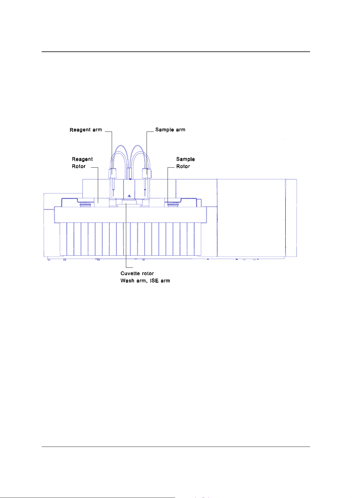
In the figure below you find an overview of the main functional units of the analyser.
Figure 2.1 – Overview of the analyser
2.1.2 SAMPLE ROTOR
The various instruments can have different sample rotors.
Refer to the special pages for the various machines for the right rotor.
A stepper motor drives the rotor.
2.1.3 REAGENT ROTOR
There are 24 positions for 25 ml bottles and 8 positions for 7 ml bottles in the reagent
rotor. Some openings for 25 ml bottles can be combined to fit 50 ml bottles.
Adapters for a placing a 7ml bottle on a 25 ml position are also available.
All positions can be assigned as Reagent 1 or 2 (start reagent)
The reagent disk compartment can be cooled by an external cooling unit.
A stepper motor drives the reagent rotor.
Some instruments have an optional special reagent rotor.
VIT AL SC IE NT IFIC 2.1

2. FUNCTIONAL DESIGN SERVICE MANUAL
2.1.4 SAMPLE ARM
The sample needle aspirates a programmed volume and will dispense it into a
cuvette of the cuvette rotor. After pipetting, the sample needle mixes the reaction
mixture. After sampling and mixing the needle will be washed inside and outside.
Because the sample arm has to move in two directions, two stepper motors;
horizontal and vertical drive the sample arm. The sample arm is equipped with a
leve l de te c t or that w i l l det e c t th e l iq uid lev e l o f the s a mple cu p and will generate an
error message when not enough sample is present in the cup.
2.1.5 REAGENT ARM
The reagent needle w ill aspirate a programmed reagent volume and will dispense it
into a cuvette of the cuvette rotor. After pipetting (reagent 2) the reagent needle will
mix the mixture in the cuvette. Then the needle will be washed inside and outside.
The reagent arm must be able to move in two directions and is therefore driven by
two stepper motors. The reagent arm is equipped with a level detector to check if
sufficient reagent is present. It is also equipped with a controlled heating element to
preheat the cooled reagent.
2.1.6 ISE ARM
Optionally the instrument is equipped with an ISE-arm to connect the instrument to
an option al external ISE (Ion Selectiv e Electrode) measuring unit.
This external ISE unit is controlled by the instrument and the ISE arm aspirates
sample from the cuvette rotor. The ISE arm is integrated in the mixer unit.
2.1.7 PIPETTORS
The two Hamilton syringes, a 1000 µl and a 100 µl type, are used in combination
with two valves for reagent and sample pipetting.
The pipetting system is water filled with air bubble separation.
A stepper motor drives each syringe, and the detection of the syringe up and down
positions is done by opto-switches.
2.2 VITAL S CIEN TIFIC

SERVICE MANUAL 2. FUNCTIONAL DESIGN
2.1.8 CUVETTE ROTOR
The cuvette rotor contains 48 cuvettes, which are thermostatted at 37 °C.
The path length of a cuvette is about 7mm, but absorbance values are re-calculated
to 10 mm path length. A stepper motor drives the cuvette rotor.
The heating of the cuvette rotor is done by means of two controlled Peltier elements.
The cover of the cuvette rotor is equipped with a heating element to avoid
condensation at the inside o f this cover.
2.1.9 WASHING UNIT
The washing unit washes the cuvettes after usage. At the first 4 positions of the
washing unit a long needle aspirates the cuvette contents and a short needle fills the
cuvette with water. At the fifth position the water is aspirated, at the sixth position a
drying block dries the cuvette.
With the option concentrated waste installed the liquid aspirated at the first cleaning
action (i.e. the reaction mixture) is lead to the concentrated waste deposit.
The washing unit is equipped with liquid sensors to detect flooding of the cuvette.
2.1.10 COOLING UNIT
Cooling of the reagents is done by means of an external cooling unit.
This unit keeps the cooling liquid in the container at a fixed temperature, which must
be set at the cooling unit.
On its turn the cooling liquid is pumped through a heat exchanger in the analyser
where cool air is fed through a closed reagent compartment.
VIT AL SC IE NT IFIC 2.3
2. FUNCTIONAL DESIGN SERVICE MANUAL
2.2 TIMING PRINCIPLE
The ins trumen t always w o rk s wit h a fixed cycl e ti me. In this fixed cycle all the
necessary dispensing, mixing, washing and diluting take place and also a fixed
number of measurements are made, regardless if they are necessary or not.
This fixed cycle assures that all the necessary measurements for a test always take
place at the right moment. Even if no measurements have to be taken (for example
during washing of the first cuvettes) the cycle takes place. In that case the reading of
the photometer is ignored.
There are two operating modes, the Mono Mode, for single reagent use, and the
Dual Mode, where a second reagent can be used. The user can switch over from the
Mono Mode to the Dual Mode, but not during testing. After switching from one mode
to the other the instrument will reset.
2.2.1 MONO MODE CYCLE
The Mono Mode has a cycle time of 20 seconds, so the theoretical throughput of the
instrument is 180 tests/hour (3x60). In practice the throughput is a little less, due to
possible sample blanks and the start-up time which is 13 minutes.
In the figure below you find a graphic representation of the 20-second cycle.
The line represents the cuvette that starts at the sa mple dispensing position.
Figure 2.2 Graphic representation Mono cycle
Note that afte r every cycle th e cuvette rotor shifts one position.
2.4 VITAL S CIEN TIFIC

SERVICE MANUAL 2. FUNCTIONAL DESIGN
As a result of this cycle after 48 cycles all cuvettes have been washed, pipetted and
measured. In the table you will find the order of actions for the individual cuvettes:
Action Time (sec) min : sec
Washing of t he c uvette -120 to –70
Reagent dispensing -50
Reagent blank -10
Sample addition and mixing 0 00:00
K 1 (measuring kinetic point 1) 12 00:12
K 2 32 00:32
Sample aspiration for ISE
K 3 51 00:51
K 4 70 01:10
K 5 90 01:30
K 6 110 01:50
K 7 129 02:09
K 8 148 02:28
K 9 168 02:48
K 10 188 03:08
K 11 207 03:07
K 12 226 03:46
K 13 246 04:06
K 14 266 04:26
K 15 285 04:45
K 16 304 05:04
K 17 324 05:24
K 18 344 05:44
K 19 363 06:03
K 20 382 06:22
K 21 402 06:42
K 22 422 07:02
Endpoint measurement (Bichromatic) 690 11:30
VIT AL SC IE NT IFIC 2.5
2. FUNCTIONAL DESIGN SERVICE MANUAL
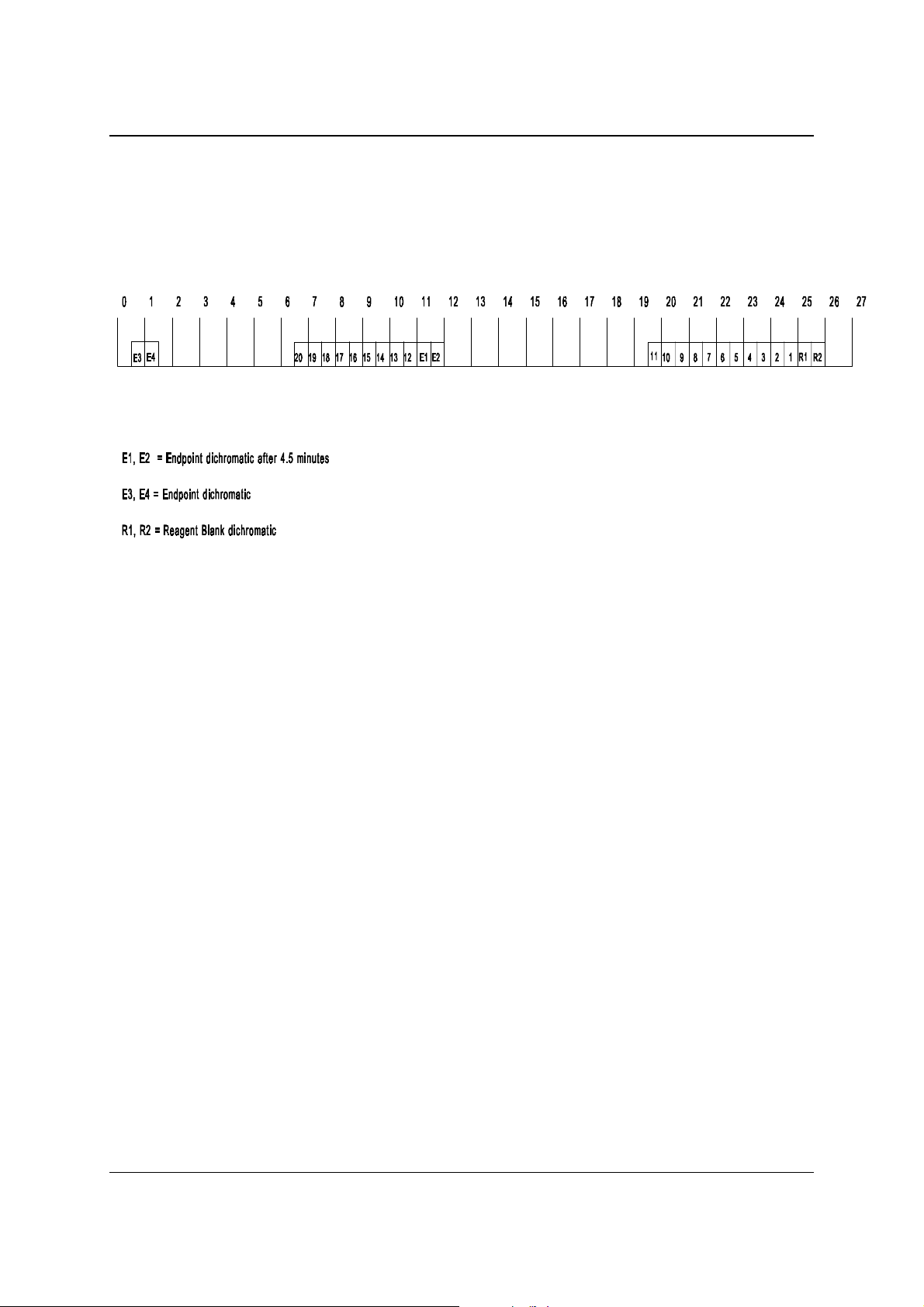
2.2.2 DUAL MODE CYCLE
The cycle time of the Dual Mode is 27 seconds, therefore the theoretical throughput
of the instrument is 133 tests/hour.
In the figure below the sequence of the 27 seconds cycle is shown.
Figure 2.3 - The 27-second cycle
Because in the Dual Mode use can be made of a second (or starter) reagent in this
cycle there is time for the second reagent to be dispensed and mixed.
Instead of dispensing a second reagent, these extra 7 seconds can also be used for
predilution of a sample. In case of predilution, in one cycle the sample is added to
the diluent, and in the next cycle (in the extra 7 seconds) the diluted sample is picked
up by the sample needle and dispensed in the next cuvette, which already contains
the appropriate reagent.
2.6 VITAL S CIEN TIFIC

SERVICE MANUAL 2. FUNCTIONAL DESIGN
The table below shows the timing in the dual mode for each individual cuvette
Action Time after
sample addition
Wash ing of the cuvette
Reagent 1 dispensing -135
Reagent blank (Bichromatic) -3
Sample addition and mixing 00:00
K 1 (measuring kinetic point 1) 00:24
K 2 00:50
Sample aspiration for ISE 00:54
K 3 01:17
K 4 01:43
K 5 02:10
K 6 02:36
K 7 03:03
K 8 03:29
K 9 03:56
K 10 04:22
K 11 / Blank before a ddi n g re ag en t 2 04:40
dispensing reagent 2 and mixing 04:43 00:00
K 12 04:49 00:06
K 13 05:07 00:24
K 14 05:33 00:50
K 15 06:00 01:17
K 16 06:26 01:43
K 17 06:53 02:10
K 18 07:19 02:36
K 19 07:46 03:03
K 20 08:20 03:29
K 21 08:39 03:56
Endpoint measurement (Bichromatic) 11:15
Time after
Reagent 2 addition
VIT AL SC IE NT IFIC 2.7

2. FUNCTIONAL DESIGN SERVICE MANUAL
2.3 MECHANICAL DESIGN
2.3.1 REAGENT ARM
The reagent arm is responsible for the moving of the reagent needle to the correct
position. The construction of the arm is such that the driving for the movements is
decoupled; separate stepper motors drive the up/down movement and the sidewardrotating movement.
The reagent arm has in fact seven discrete horizontal positions in which the arm
normally is positioned. A reset opto and a subsequent number of stepper motor
steps determine these positions.
Horizontal: Cuvette position
Wash p o sitio n
5 * Reagent Rotor position
There are t hr e e discr e te vertical positi o n s and one variable vertical po sition:
Vertical: Up (or reset) position
Cuvette position
Wash p o sitio n
Reagent (variable value, depending on the liquid level in the
reagent bottle
For the discrete positions a value will be a ss igned with r espect to the reset position,
which will comply with the number of steps the stepper motor needs for the arm to
reach its destination.
The variable position for the reagent level indicates the arm to lower itself just below
the reagent level in the bottle (enough to aspirate 400 µl).
This position is determined by a level detection and the subsequential lowering with
a predefined number of steps.
2.8 VITAL S CIEN TIFIC

SERVICE MANUAL 2. FUNCTIONAL DESIGN
2.3.2 SAMPLE ARM
The sample arm is responsible for moving the sample needle in the correct position.
The construction of the arm is such that the driving for the movements is decoupled;
separate stepper motors drive the up/down movement and the sideward-rotating
movement.
The sample arm has five discrete horizo n ta l posi tions , which are represented by five
stepper motor co-ordinates:
Horizontal: Cuvette position
Wash p o sitio n
Sample rotor outer position
Sample rotor middle position
Sample rotor inner position
In the vertical direction there are three discrete and one variable position:
Vertical: Up or reset position
Cuvette position
Wash p o sitio n
Sample position (variable position, dep ending o n the sa mple volume)
2.3.3 REAGENT AND SAMPLE ROTOR
The reagent rotor has 32 discrete positions that cor respond with the 32 reagent
bottle positions, although optional different reagent rotors are possible.
The sample rotor has 72 discrete positions that correspond with the 72 sample cup
positions.
2.3.4 MEASURING UNIT
The measuring unit consists of the following items mounted together as one unit:
• measuring rotor
• filter wheel with lamp unit
The measuring rotor is stepper motor driven and the reset position is detected by an
opto-switch.
The measuring rotor has 48 discrete positions that correspond w ith the 48 cuvettes
which must be positioned in the lightpath. Since a full turn of the stepper motor is
2400 steps, the distance between two cuvettes is 50 steps.
Two Peltier elements are mounted under the measuring rotor to heat the cuvettes.
The selection of the wavelength is done by means of an 8-position filter wheel.
The standard mounted filters are 340, 376, 405, 436, 505, 546, 578, and 620 nm.
The filter wheel has 8 discrete positions that are 48 steps away from each other.
The reset position is detected by an opto-switch.
The lamp unit consists of a lamp holder with a mechanism for adjusting the lamp.
VIT AL SC IE NT IFIC 2.9
2. FUNCTIONAL DESIGN SERVICE MANUAL
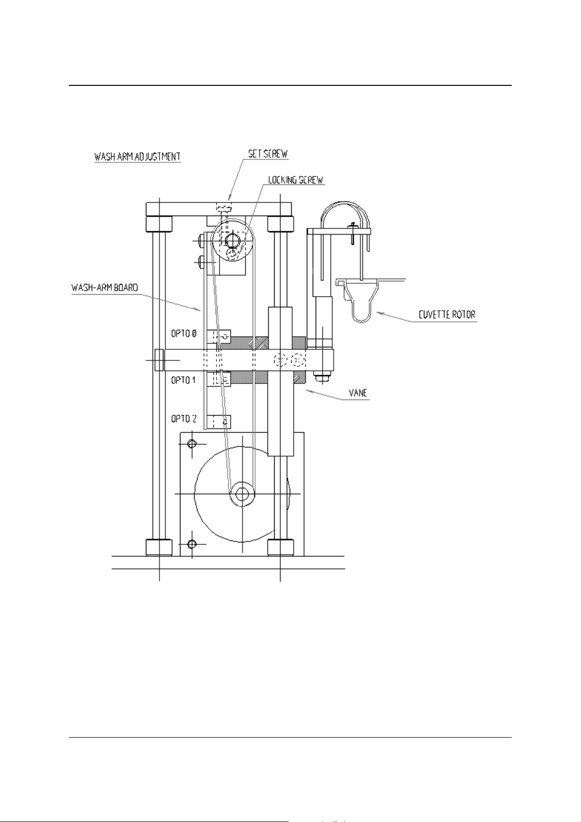
2.3.5 WASH UNIT AND BELLOWS PUMP
The wash unit is built up with a stepper motor that is driving via a timing belt the
wash arm.
Figure 2.4 - Wash unit
The positions of the wash arm are detected by three opto-switches.
The opto-switches are mounted on a PCB (the so-called wash arm board).
The wash unit normally has three vertical positions . Du ring normal operation two of
them are accessed; up and down. Opto 1 is for detecting the up position and opto 2
is for the down position. Opto 0 is for detecting the high position of the wash arm (for
changing of the cuvette rotor).
2.1 0 VIT AL SC IE NT IFIC

SERVICE MANUAL 2. FUNCTIONAL DESIGN
During the reset also the presence of the cuvette rotor is detected.
The wash arm will go downwards until it touches the bottom of the cuvette.
At this position opto 1 the vane is still positioned in opto 1. When no cuvette is
present, the vane is not in opto 1, and error NO CUVETTE will be displayed.
Wash arm opto readings at the various wash arm positions:
High Up Dow n Detection of “no cuvette” during reset
Opto 0 1 0 1 1
Opto 1 1 0 0 1
Opto 2 1 1 0 0
The bellows pump consists of six separate bellows mounted together in one unit.
A stepper motor drives the bellows. The bellows pump has two defined positions; a
zero position and a predefined full stroke vol ume position (500 µl is equal to 833
steps). The detection of both positions is done by opto-switches.
VIT AL SC IE NT IFIC 2.1 1
2. FUNCTIONAL DESIGN SERVICE MANUAL
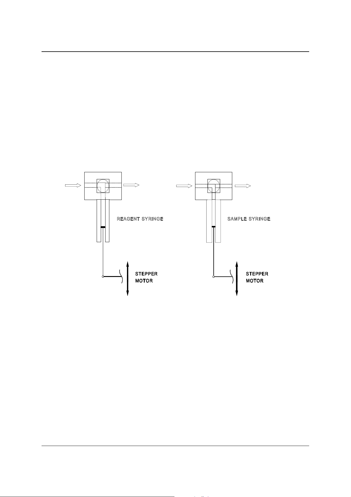
2.3.6 PIPETTOR
The pipettor is a precise dilut er with moto r driven valves and syringes.
The pipettor is controlled by one of the Motion Control Boards.
The liquid displacement is contro lled by two stepper motor driven syringes:
the sample syringe (100 µl) and the reagent syringe (1000 µl).
Each syringe is connected to a special connection block that contains the valve unit.
The valves are driven by small DC-motors via a worm-wheel construction.
The syringe drive assembly is shown in figure 2.5.
The top and bottom position of the plunger is detected by two opto-switches.
Figure 2.5 – Syringe drive assembly
The lower opto is also used for home initialisation, during the reset.
The four opto’s are mounted together on a separate PCB.
The syringes are made of glass and the plungers are teflon-tipped.
The tubes that are connected to the valves are also made of teflon.
2.1 2 VIT AL SC IE NT IFIC