

Vita Fairfield Grande Arbor Instruction Manual
A S S EM B LY I N S T R U C T I ON S
www.wearevita.com
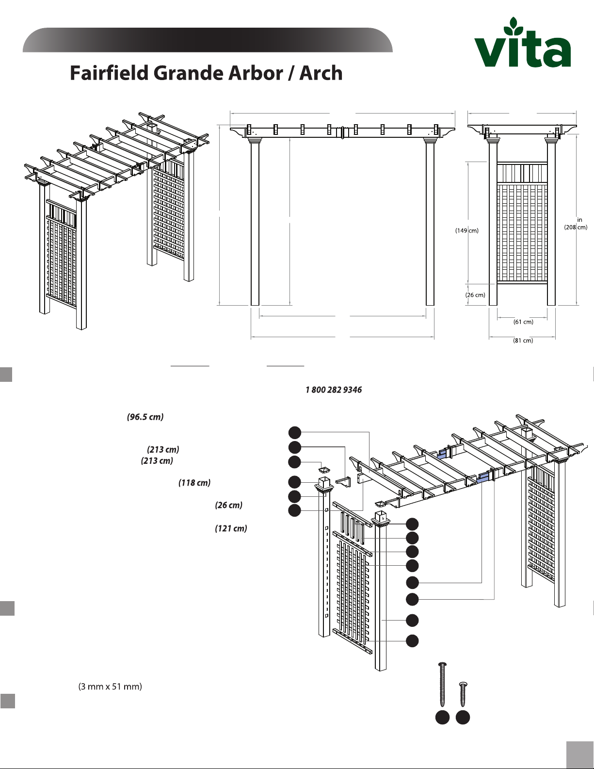
107.75 in
(274 cm)
86.5 in
(220 cm)
Please read through before sta rting assembly.
80.5 in
(204 cm)
80 in
(203 cm)
88 in
(224 cm)
IMP ORTANT: CHECK THE IN SIDE OF YO UR PO STS FOR ALL MATERI ALS.
Check Box for These Content s
(Mon. to Fri. 8:00 AM to 5:00 PM EST).In the event of missing or defective parts please call our customer service dept. at
10.3 in
58.5 in
52.25 in
(133 cm)
24 in
32 in
82
-
1. Rafters (8)
2. Pergola End Caps (20)
3. Post Caps (4)
4. Right Posts (2)
5. Left Posts (2)
6. Post T rims (4)
7. Carrying Beams (4)
8.
Side Panel T op-Rails
Length 38"
- 10824
Length 84"
Length 84"
- 10737-1
Length 46 1/2"
(2)
- 10700-1
Length 31 5/8“ (80 cm)
9. Side Panel V ertical Spindles
10. Side Panel Middle Rails (2)
11. Side Panel Square Lattices (2)
12. Aluminum Stiffener Inserts (2) - 10996
13. Carrying Beam Coupler (2) - 10707-1
14. Side Panel Horizontal Bottom R ails (2)
in. (76 m.)
15.
3
16.
1 1/2 in. (38 mm.) Stainless Steel Screws (12)
17.
T ube of V inyl Glue (2) - 20000
Stainless Steel Screws
10838
-
10792
-
10821
- 10839
- 10822
Length 10 3/8”
-
10795
Length 31 5/8“ (80 cm) - 10823
Length 47 3/4”
- 10793
Length 31 5/8" (80 cm)
(32)
- 20007
- 20005
1
2
3
4
6
7
- 10794
Tools Y ou Will Need
• Hammer
• Tape Measure
• Level
• Stool or Short Ladder
• Shovel or Auger
• Cordless Drill
• 1/8” x 2” Steel Drill Bit
General In form ation
•
Rea d Instr uctions through carefu lly before beginning assembly.
• When assembling components, place on a non-abrasive surface
(i.e. shipping box) to avoid scratching.
• We recommend an area approx 10’x 8' (3 m x 2.4 m) for unobstructed assembling.
• You should not need to use excessive force when assembling components.
8
9
10
11
12
13
5
14
15
16
(Not to scale)
V2.7/111720
1
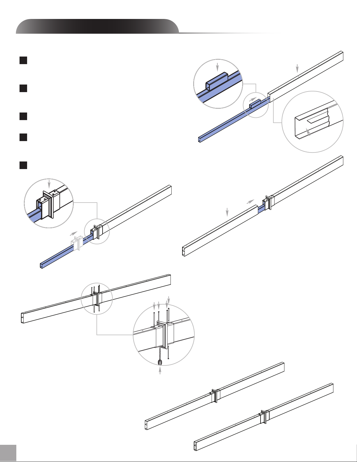
STE P ON E
Assemble the Arbor Beams
Insert one stee l stiffener (with ste el block facing up ) into the
1
lowe r pocke t of the bea m past the joiner. Push until steel block
hits the internal ribbing.
Slide the beam coupler over the beam. Install the coupler so
2
that the four holes are facing up. Push firmly until the couple r
bottoms out on the beam.
Slide a second beam coup ler over the steel insert and into the
3
coupler.
Screw the coupler to the vinyl beams and steel using 1 1/2” (38
4
mm) screws. The bottom and top holes will need to be predrilled using the stee l drill bit (not provided)
Repeat for secon d beam.
5
Four holes facing up
Steel block should be facing up
1
Predrilled holes facing up
Beam rib
is removed to
accomodate steel
stiffener
Predrilled holes facing up
3
2
4
2
Pre-drill holes on bottom and top to
accomodate for internal steel stiffener.
5
Fairfield Grande Arbor / Arch
 Loading...