

Page 1
Integrated High Speed Dome Camera Quick Guide
1
This Quick Guide is a reference for users to install and operate the Camera quickly, and thus only provides basic
information on the Camera’s various setting and operation. Before attempting to connect, configure and operate
the Camera, please read its Installation Guide, User’s Manual and OSD Menu thoroughly.
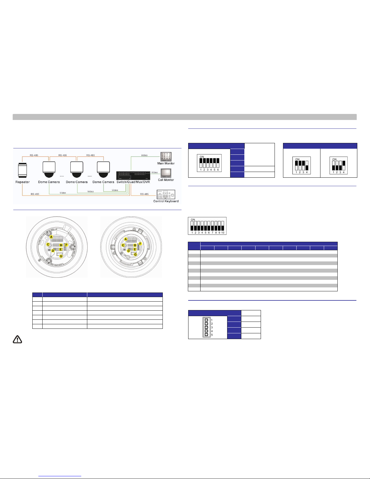
System Configuration
Switch Definition
Indoor Outdoor
Please kindly check the pin definition of the Power Connector listed above before connecting to the p ower
source. The AC24V power source should be connected to the first and third pin. The unit might be
damaged with wrong connection.
Communication Switch Setting
The table below shows the function of each switch within the Communication Switch o n the Camera’s back
plate.
Communication Switch
SW 1
RS-485 Setting
RS-485 Setting
SW 2
Half-duplex
Full-duplex
SW 3
SW 4
SW 5
Reserved
SW 6
Reserved
ID Setting
Please assign an ID number to a Camera if there is more than one Camera in the same network. The camera’s
ID can be setup using the 10-bit ID Dip Switch, which is located on the Camera’s back plate. If the Camera’s ID
number is 6, f or instance, the ID switch SW 2 and SW 3 should be set to “ON” and the rest should be set to
“OFF” as shown below. Dip Switch configuration for ID No. 0~10 are listed in the table below. To complete ID
setups, please refer to the User Manual.
ID No.
Switch Setting
SW 1 SW 2 SW 3 SW 4 SW 5 SW 6 SW 7 SW 8 SW 9 SW 10
0
OFF OFF OFF OFF OFF OFF OFF OFF OFF OFF
1
ON OFF OFF OFF OFF OFF OFF OFF OFF OFF
2
OFF ON OFF OFF OFF OFF OFF OFF OFF OFF
3
ON ON OFF OFF OFF OFF OFF OFF OFF OFF
4
OFF OFF ON OFF OFF OFF OFF OFF OFF OFF
5
ON OFF ON OFF OFF OFF OFF OFF OFF OFF
6
OFF ON ON OFF OFF OFF OFF OFF OFF OFF
7
ON ON ON OFF OFF OFF OFF OFF OFF OFF
8
OFF OFF OFF ON OFF OFF OFF OFF OFF OFF
9
ON OFF OFF ON O FF OFF OFF OFF OFF OFF
10
OFF ON OFF ON OFF OFF OFF OFF OFF OFF
RS485 Connector Definition
Please refer to the illustrations below for RS485 connector definition before wiring.
RS485 Connector SW 1
R-
SW 2
GND
SW 3
R+
SW 4
T-
SW 5
T+
Item
Definition Remark
A
I/O
ALARM I/O
B
ID Dome Camera ID Setup DIP Switch
C
BNC BNC Video Output
D
SETTING Communication Switch Setting
E
Protocol Camera Control Protocol Setting
F
RS485 RS485 Connector
G
AC24V Connector Power connector
Page 2
00P5DH820ZXSEA3
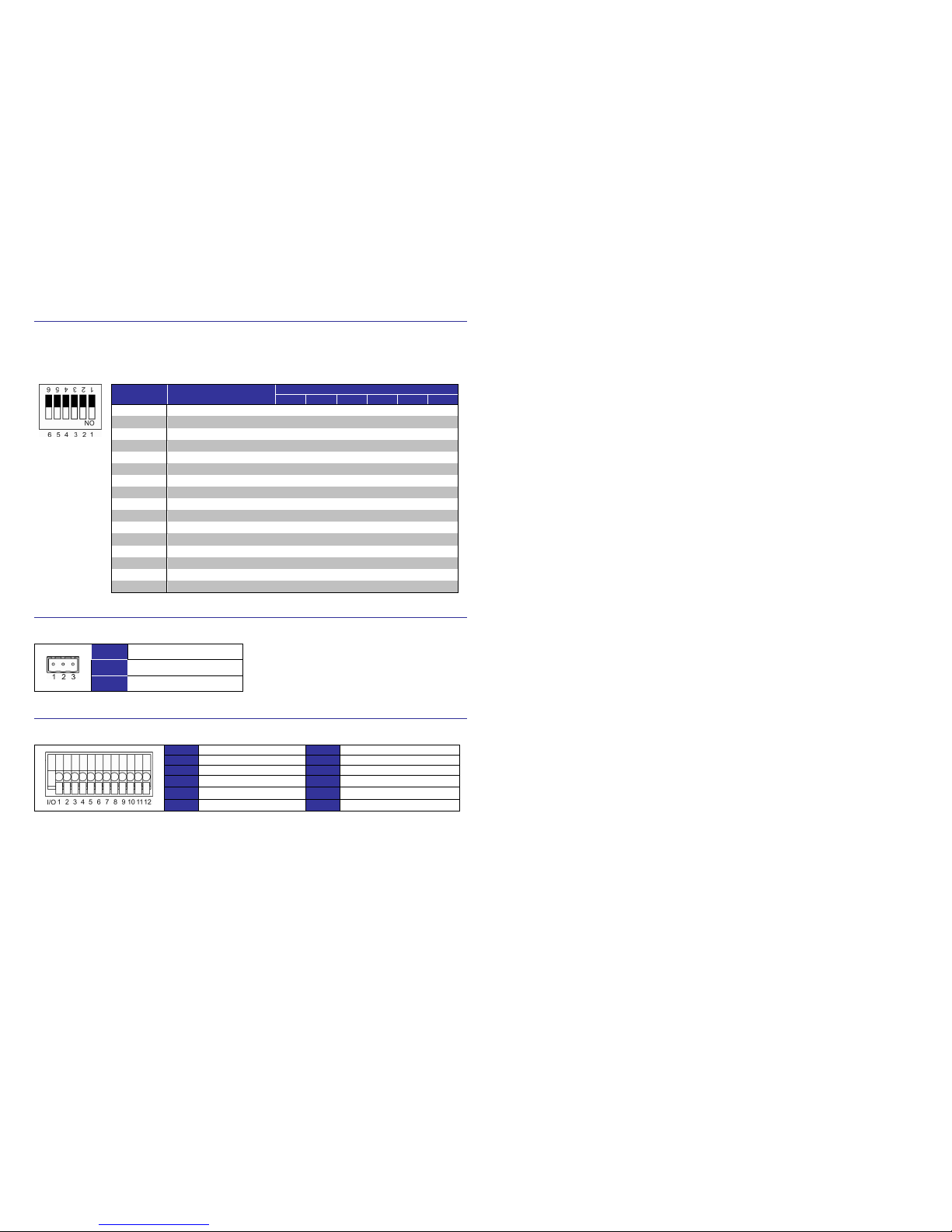
Camera Control Protocol Setting
Refer to the table below and select one set of protocol and baud rate you would like to use basing on the control
device; then adjust the protocol switch on the Camera’s back plate. For instance, to setup protocol Pelco D/
Baud Rate 2400, which is Switch No. 01, the Switch SW 1 should be set to “ON”, and the rest Switches should
be set to “OFF”.
Switch No. Protocol Baud Rate
Switch Setting
SW 1 SW 2 SW 3 SW 4 SW 5 SW 6
00
VCL 9600 OFF OFF OFF OFF OFF OFF
01
Pelco D 2400 ON OFF O FF OFF OFF OFF
02
Pelco P 4800 OFF ON OFF OFF OFF OFF
04
Chiper 9600 OFF OFF ON OFF OFF OFF
05
Philips 9600 ON OFF ON OFF OFF O FF
07
DSCP 9600 ON ON ON OFF OFF OFF
08
AD422 4800 OFF OFF OFF ON OFF OFF
09
DM P 9600 ON OFF O FF ON OFF OFF
11
Pelco D 4800 ON ON OFF O N OFF OFF
12
Pelco D 9600 OFF OFF ON ON OFF OFF
13
Pelco P 2400 ON OFF ON ON OFF OFF
14
Pelco P 9600 OFF ON ON ON OFF OFF
15
JVC 9600 ON ON ON ON OFF OFF
21
Kalatel-485 9600 ON OFF ON OFF ON O FF
22
Kalatel-422 4800 OFF ON ON O FF ON OFF
23
Panasonic 19200 ON ON ON OFF ON OFF
Power Connector Definition
Please refer to the illustrations below for power connector definition before wiring.
SW 1
AC24V_1
SW 2
GND
SW 3
AC24V_2
Alarm I/O Connector Definition
When cabling, please refer to the pin definition as below for alarm system alarm.
SW 1
ALARM_OUT_NO_1
SW 7
ALARM_OUT_COM_2
SW 2
ALARM_OUT_NC_1
SW 8
GND
SW 3
ALARM_OUT_COM_1
SW 9
ALARM_IN_4
SW 4
GND
SW10
ALARM_IN_3
SW 5
ALARM_OUT_NO_2
SW11
ALARM_IN_2
SW 6
ALARM_OUT_CN_2
SW12
ALARM_IN_1
Integrated High Speed Dome Camera
Quick Guide
Ver 1.3
 Loading...