

Page 1

400
VIDEO
DISPLAY
TERMINAL
REFERENCE
MANUAL
Visual Technology Incorporated
540
Main
Street, Tewksbury, MA
01876 ,
Telephone
(617)
851
-50
00,
Telex
951
-539
Printed in U.S.A.
Page 2

WARNING
This equipment generates,
if
not
installed
cause
interference
regulation
it
has
and
used
in accordance
to
radio communications. As temporarily permitted
not
been
tested
computing devices pursuant
designed
ation
which
measures
to
provide reasonable protection against such interference. Oper-
of
this equipment in a residential
case
the user at his own expense
may
be
required
to
uses,
and
can
radiate radio frequency energy and
with
the instruction manual may
for
compliance
to
Subpart J
of
area
will
Part 15
is
likely
be
required
correct the interference.
with
the
limits
of
FCC
to
cause
to
take whatever
by
for
Class
Rules which
interference in
A
are
Page 3

VISUAL
TECHNOLOGY
INCORPORATED,
540
MAIN
STREET,
TEWKSBURY,
MA
01876
VIDEO
DISPLAY
REFERENCE
TERMINAL
MANUAL
June
1981
Page 4

VISUAL
TECHNOLOGY
INCORPORATED, 540
SAFETY WARNING
MAIN
STREET, TEWKSBURY,
MA
01876
Hazardous voltages 115, 220 V AC
,terminal
working
When
phosphor
CRT tube
is
on, and may remain after power
on
internal circuits, and do
handling the cathode ray tube caution
is
toxic. Safety
is
handled. Should the tube break, skin
goggles
phosphor, rinse the affected
terminal
This
use
not
use
any adaptor which will defeat the safety ground.
Insure
that
keyboard
is
supplied
this terminal
power
is
cable.
with
with
turned
an
off
and
15
KV
is
not
work
is
and
gloves
area
with cold water and consult a physician.
a cord
set
must
that
includes a safety ground. Do
ungrounded outlet, missing ground pin,
before connecting
PREFACE
This manual describes the features and operation
display terminal. Programming
first
level
service information
nance
information,
please
and application information together
is
also included. For second
consult the
VISUAL
Manual.
DC
are
present when the
removed.
Use
caution when
alone.
required
of
as
the internal
be
used
whenever the
or
eyes
exposed
or
disconnecting the
the
VISUAL
level
mainte-
100/400 Maintenance
to
400
the
or
with
This manual
intended
after the date
is
published and distributed by Visual Technology Inc.
for
reference only. The contents
of
the written consent
printing. This manual may
of
Visual Technology, Inc.
and
specifications may
not
be
reproduced
and
change
without
is
Page 5

VISUAL
TECHNOLOGY
INCORPORATED,
540
MAIN
TABLE OF CONTENTS
STREET,
TEWKSBURY,
MA
01876
Page
INTRODUCTION
1.
1.1
COMMONLY
SPECIFICATIONS/CHARACTERISTICS
2.
2.1
KEYBOARD
2.2
VIDEO MONITOR AND COMPOSITE VIDEO
2.3
P.C.B.
AND
2.4 GENERAL
START-UP PROCEDURES
3.
3.1
INSTALLATION
3.2 SET-UP
3.2.1
General
3.2.1.1 How
3.2.1.2 How
3.2.1.3 How
..................................................
USED
TERMS
..................................................
COMMUNICATION INTERFACE
SPECI
FICATIONS
...........................................
...............................................
MODES
................................................
.................................................
to
to
to
3.2.1.4 Performing a
3.2.1.5 Performing a SAVE
3.2.1.6 Performing a RESET Operation
3.2.2 SET-UP Feature Definitions
3.2.2.1 Line/Local
3.2.2.2
3.2.2.3
3.2.2.4
Column Mode
Tabs
...........................................
Screen
Brightness
3.2.2.5 Scrolling Mode
3.2.2.6 Autorepeat Mode
3.2.2.7
3.2.2.8
Screen
Mode
Cursor Selection
3.2.2.9 Margin Bell
3.2.2.10 Keyclick
3.2.2.11 Transmitter
3.2.2.12
ReceiverXON/XOFF
3.2.2.13 Line Transmit Mode
3.2.2.14 Autowrap Mode
3.2.2.15 Linefeed New Line Mode
3.2.2.16
Auto
Tab Mode
3.2.2.17 Parity Enable
3.2.2.18 Parity
3.2.2.19 Bits
3.2.2.20
Refresh
Sense
Per
3.2.2.21 Duplex
3.2.2.22 Local Echo
3.2.2.23 Turn Around
......................................
................................
........................
........................
....................................
Enter SET-UP
Determine the Status
Change
SET-UP Features
MODE'
.......................
of
SET-UP Features
.....................
RECALL Operation . ~ ..................
Operation
.......................
......................
...............................
......................................
....................................
.................................
...................................
.................................
.....................................
................................•..
......................................
........................................
XON/XOFF
...........................
..............................
...............................
..................................
...........................
........ , ..........................
.............
'
.......................
..........................
Character
Rate
.................................
....................................
.........................................
......................................
....................................
........
:
..........
.
.
.
.
.
.
.
.
.
.
.
.
1
1
3
3
3
3
7
9
9
9
9
10
.
.
.
.
.
.
.
.
.
.
.
.
.
~~
17
17
17
17
17
18
18
18
18
19
19
19
.
.
.
.
.
.
.
.
.
.
.
.
.
.
.
19
19
19
19
20
20
20
20
20
20
20
20
21
21
21
iii
Page 6

VISUAL
TECHNOLOGY
INCORPORATED,
540
MAIN
STREET,
TEWKSBURY,
MA
01876
TABLE
3.2.2.24 Character/Block Mode
OF
CONTENTS - Continued
.............................
3.2.2.25 Control Representation Mode
3.2.2.26 Erasure Mode
3.2.2.27 Vertic
Ie
3.2.2.28 Horizontal Editing Mode
3.2.2.29
Edit
Boundary Mode
3.2.2.30 Select Editing
....................................
Editing Mode
Extent
.............................
...........................
..............................
Mode
3.2.2.31 . Guarded Area Transfer Mode
3.2.2.32
3.2.2.33
3.2.2.34
3.2.2.35
3.2.2.36
3.2.2.37
3.2.2.38
3.2.2.39
3.2.2.40
3.2.2.41
3.2.2.42
3.2.2.43
3.2.2.44
3.2.2.45
Transmit Request Mode
Multiple Area Transfer Mode
Transfer Termination Mode
Modified Data Area Transfer Mode
Page
Transfer Mode
Xmit
Speed
Receive
Answerback
Select Keyboard
Start
of
Area Separator Code (AS)
First
and
First
and
Turn Around Control Code (TACC)
.....................................
Speed
Message
Second End
Second End
...................................
Message
layout
Code (SaM)
............................
...............................
..............................
............................
..........................
of
Line Codes
of
Message
.......................
.........................
........................
........................
.........................
...................
........................
(FEOl & SEOl)
Codes
(FEOM & SEOM)
...................
.....
Page
.
.
.
.
.
.
.
.
.
.
. 22
.
.
. 22
.
;,,~>
.
. 23
. 24
.
. 24
..
.
21
21
21
21
21
21
21
22
22
22
22
22
22
22
24
25
25
4.
KEYBOARD
5.
TERMINAL
5.1
5.2
5.3
CONTROLS
PROGRAMMING
GENERAL
CONTROL CODES
CONTROL SEQUENCE FUNCTIONS
5.3.1
5.3.2
5.3.3
5.3.4
5.3.5
....................................................
Scrolling Region Command
Cursor Movement Commands
Tabbing Commands
Erasure Commands
Character Size
AND
l.E.D.'S
........................................
.............................................
.......................................
........................................
and
Screen Alignment Commands
............
...............................
.................................
................................
5.3.6 Program Function Key Command
5.3.7 Program
5.3.8
5.3.9
5.3.10
5.3.11
5.3.12
5.3.13
Save/Restore Cursor Commands
Report Commands
Test Command
Character Set Commands
Editing Commands
Set Commu nication Control
lED
Command
and
...........................................
........................................
...................................
Responses
...................................
Codes
iv
~
....................
.................
............................
..............................
............................
Command
...................
.
. 33
. 33
. 34
.
. 35
.
. 37
. 39
.
.
. 42
. 42
.
.
.
.
.
27
34
35
41
41
42
43
44
44
47
Page 7

VISUAL
TECHNOLOGY
INCORPORATED,
540
MAIN
STREET,
TEWKSBURY,
MA
01876
TABLE
OF CONTENTS - Continued
Page
5.3.14 Video
5.3.15 Remote Transmit Command
5.3.16
5.3.17 Define Area Qualification Command
5.3.18
Clear
Attribute
Command. . . . . . . . . . . . . . . . . . . . . . . . . . . . . . . . . . . 48
.................................
Reset
Command . . . . . . . . . . . . . . . . . . . . . . . . . . . . . . . . . . . . . . . . . . . 48
...........................
Attribute
Code Command . . . . . . . . . . . . . . . . . . . . . . . . . . . . . . .
48
48
51
5.4 MODES (SET/RESET) . . . . . . . . . . . . . . . . . . . . . . . . . . . . . . . . . . . . . . . . . . . . 53
5.4.1 Guarded Area Transfer Mode . . . . . . . . . . . . . . . . . . . . . . . . . . . . . . . . . 55
5.4.2 Keyboard
5.4.3
5.4.4
Control Representation Mode
Insert Replace
5.4.5 Erasure
5.4.6 Vertic
5.4.7
Horizontal Editing Mode
Action
Mode.
Ie
Editing Mode
5.4.8 Character Mode
5.4.9
Multiple Area Transfer Mode
5.4.10 Transfer Termination
Mode
.....................................
................................
Mode.
. . . . . . . . . . . . . . . . . . . . . . . . . . . . . . . . . . . . . . . 56
. . . . . . . . . . . . . . . . . . . . . . . . . . . . . . . . . . . . . . . . . . . . 56
......................................
....................................
...........................................
...
. . . . . . . . . . . . . . . . . . . . . . . . . . . . . . 57
Mode.
. . . . . . . . . . . . . .
..
. . . . . . . . . . . . . . . . . 58
56
56
57
57
57
5.4.11 Linefeed New Line Mode . . . . . . . . . . . . . . . . . . . . . . . . . . . . . . . . . . . . 58
5.4.12
Protect
5.4.13 Autotab Mode
5.4.14 Modified Data Area Transfer Mode
5.4.15
5.4.16
5.4.17
5.4.18
Column
Scrolling
Screen
Origin Mode . . . . . . . . . . . . . . . . . . . . . . . . . . . . . . . . . . . . . . . . . . . . . .
5.4.19 Autowrap Mode . . . . . . . . . . . . . . . . . . . . . . . . . . . . . . . . . . . . . . . . . . .
5.4.20 Autorepeat
5.4.21 Transmit Request
5.4.22 Line Transmit
5.5 SELECT EDITING EXTENT
Mode............................................
............................................
............................
Mode.
Mode.
Mode.
. . . . . . . . . . . . . . . . . . . . . . . . . . . . . . . . . . . . . . . . . . . . 59
. . . . . . . . . . . . . . . . . . . . . . . . . . . . . . . . . . . . . . . . . . . 59
. . . . . . . . . . . . . . . . . . . . . . . . . . . . . . . . . . . . . . . . . . . . . 59
Mode.
. . . . . . . . . . . . . . . . . . . . . . . . . . . . . . . . . . . . . . . . .
Mode.
Mode.
. . . . . . . . . . . . . . . . . . . . . . . . . . . . . . . . . . . .
. . . . . . . . . . . . . . . . . . . . . . . . . . . . . . . . . . . . . . .
MODE.
. . . . . . . . . . . . . . . . . . . . . . . . . . . . . . . .
. 58
58
58
60
60
60
60
60
60
6.
DATA
6.1
6.2
TRANSMISSION
MODES
MESSAGE
6.2.1
.......................................................
FRAMING.
Block Mode Transmissions . . . . . . . . . . . . . . . . . . . . . . . . . . . . . . . . . . . 65
..............................................
6.2.2 Function Key, Answerback and
6.2.3 Line Drawing
6.3
HALF/FULL-DUPLEX
6.3.1
6.3.2
XON/XOFF
6.4
7.
BUFFERED PRINTER INTERFACE
7.1
GENERAL.....................................................
Half-Duplex......
Full-Duplex..............................................
SYNCHRONIZATION.. . ..
. . . . . . . . . . . . .
and
Foreign Characters. . . . . . . . . . . . . . . . . . . . . . . . . . . 66
...........
..
. . . . . . . . . . . . . . . . . . . . . . . . . . . . 63
Status Transmissions
..............
:...............................
. . . . . . . . . . . . . . . . . . . . . . . . . . . . . . . . . . . . . . . . 68
..
...
. . .
..
. .
...
. .
...
. .
.. . ...
OPTION.
. . . . . . . . . . . . . . . . . . . .
..
. . . . . .
63
63
66
68
68
. 68
71
71
Page 8

VISUAL
TECHNOLOGY
INCORPORATED,
540
MAIN
STREET,
TEWKSBURY,
MA
01876
TABLE
7.2 SET-UP P FEATURE DEFINITIONS
7.2.1
7.2.2 Printer
Copy
Mode.......................................
Controller Mode . . . . . . . . . . . . . . . . . . . . . . . . . . . . . . . . . . . . . 74
7.2.3 Auto Print Mode
7.2.4
7.2.5 Printer
7.2.6 Printer
7.2.7 LF
7.2.8
7.2.9 Parity Select
Underline Sequence. . . . . . . . . . . . . . . . . . . . . . . . . . . . . . . . . . . . . . . . 74
Busy
. . . . . . . . . . . . . . . . . . . . . . . . . . . . . . . . . . . . . . . . . . . . . . 74
Suppress
Cancel
Type.
Select
. . . . . . . . . . . . . . . . . . . . . . . . . . . . . . . . . . . . . . . . . . . . .
. . . . . . . . . . . . . . . . . . . . . . . . . . . . . . . . . . . . . . . . . . . . . . 75
.............................................
and
7.2.10 Bits per Character
7.2.11
7.2.12 Print
7.3
PRINTER COMMANDS
7.3.1
Busy
Polarity.
Speed. . . . . . . . . . . . . . . . . . . . . . . . . . . . . . . . . . . . . . . . . . . . . . . 76
Print Line/Page Commands
OF CONTENTS - Continued
................................
........
..........................................
parity Enable
...........................
...............................
" .
... . .. . ..
. . . 76
. . . . . . . . . . . . . . . . . . . . . . . . . . . . . . . . . . . . . . . . . . . . 76
AND
MODES.
. . . . . . . . . . . . . . . . . . . . . .
..
. . . . . . 76
..................................
7.3.2 Copy Mode. . . . . . . . . . . . . . . . . . . . . . . . . . . . . . . . . . . . . . . . . . . . . . . 76
7.3.3 Printer
7.3.4 Auto Print Mode
Controller Mode . . . . . . . . . . . . . . . . . . . . . . . . . . . . . . . . . . . . . 77
..........................................
Page
74
74
74
75
75
75
76
77
8
PAGING OPTION
8.1
GENERAL.....................................................
...................................................
8.2 MEMORY ORGANIZATION
8.3
ADDITIONAL
MODES.
8.3.1 Edit Boundary Mode
8.3.2
8.4
ADDITIONAL
8.4.1
8.4.2
Page
Transfer Mode
COMMANDS.
Scroll Up
Scroll Down . . . . . . . . . . . . . . . . . . . . . . . . . . . . . . . . . . . . . . . . . . . . . . 87
8.4.3 Next Page. . . . . . . . . . . . . . . . . . . . . . . . . . . . . . . . . . . . . . . . . . . . . . . . 87
8.4.4 Previous
8.4.5 Print
8.5
ADDITIONAL
8.6
MODIFIED COMMAND
8.6.1
8.6.2
8.6.3 Form
8.6.4 What
8.6.5 What
8.7 RECEIVING
8.8 OPERATION
9.
FIRST
9.1
GENE
Absolute Cursor Positioning. . . . . . . . . . . . . . . . . . . . . . . . . . . . . . . . . . 88
Horizontal
LEVEL
RAL
Page
All
. . . . . . . . . . . . . . . . . . . . . . . . . . . . . . . . . . . . . . . . . . . . . . . . . 88
KEYBOARD
Feed
is
Cursor Location Relative
is
Cursor Location Relative
DATA.
RESTRICTIONS.
MAINTENANCE.
.........................................
.................................
,.
. .
..
. . . . . . . . . . . . . . . . . . . . . . . . . . . . . . . . . . . . . . . . . . 85
.......................................
........................................
. . . . . . . . . . . . . . . . . . . . . . . . . . . . . . . . . . . . . . 87
................................................
.............................................
CONTROLS.
OPERATIONS.
and
Vertic
Ie
Position
..
. . . . . . . . . . . . . . . . . . . . . . . . . . . . . . . . . . . . . . . . . . . . . 88
. . . . . . . . . . . . . . . . . . . . . . . . . . . . 88
. . . . . . . . . .
... . ..
. .
.. . ...
. .
..
. 88
..............................
to
Screen?
to
Entire Memory? . . . . . . . . . . . . . . . 90
............
;........
. . . . . . . . . . . . . . . . . . . . . . . . . . . . . . . . . . . . . . . . . . . . . 90
. . . .
.. ..
. . . . . . . . . . . . . . . . . . . . . . . . . . . . 90
... . .....
...
.. . ..
. . . .
..
. . . . . . . . . . . . . . . .
'.
. . . . . . . . . . .
81
81
81
85
85
87
88
88
88
91
91
vi
Page 9

VISUAL
TECHNOLOGY
TABLE OF CONTENTS - Continued
INCORPORATED,
540
MAIN
STREET,
TEWKSBURY,
MA
01876
Page
9.2 REAR
9.2.1
9.2.2
9.3
TOP
9.3.1 Top Cover
9.3.2 Top Cover
9.4
PRINTED CIRCUIT BOARD
9.5
TV
9.6 CRT AND
9.7
TV
9.8
110/220
9.9
TROUBLESHOOTING
9.9.1
9.9.2
APPENDIX I -
PANEL.
Rear
Rear
COVER
. .
.. . ... . ..
Panel
Removal
Panel
Installation . . . . . . . . . . . . . . . . . . . . . . . . . . . . . . . . . . . . . .
....
...................................................
Removal
.......................................
Installation
REMOVAL
MONITOR
PCB
REMOVAL
FLYBACK
REMOVAL
MONITOR ADJUSTMENTS
VOLT
SELECTION.
...........................................
Self
Test.
Fault
VISUAL
. . . . . . . . . . . . . . . . . . . . . . . . . . . . . . . . . . . . . . . . . . . . . . . . 96
Isolation.
. . . . . . . . . . . . . . . . . . . . . . . . . . . . . . . . . . . . . . . . . . . 96
400 CONTROL SEQUENCE
. . . . .
....
..
..
. . . . . . . . . . . . . . . . . . . . . . . . . . . . . . . . . . . .
......................................
AND
AND
INSTALLATION.
AND
INSTALLATION................
....................................
. . . . . . . . . . . . . . . . . . . . . . . . . . . . . . . . . . . . . . 95
SUMMARY.
APPENDIX II - GRAPHIC RENDITION OF CONTROL
APPENDIX
APPENDIX
111- KEYBOARD LEGENDS
IV
- TURN-AROUND CONNECTOR FOR INTERFACE TESTS
AND
CHARACTER
..
. .
.. . .. . ..
. . . . .
...
INSTALLATION.........
. . . . . . . . . . . . .
. . . . . . . . . . . . . . . 99
CODES
.................
SETS.
..
. . . . . .
........
..
..
...
... . ..
.
91
91
91
92
. 92
92
. 92
. 93
93
93
96
105
107
115
APPENDIX V - DECIMAL
EQUIVALENT
OF ASCII CODES. . . . .
vii
.. . ..
. . .
..
. . . . . 117
Page 10

VISUAL
TECHNOLOGY
INCORPORATED,
LIST
OF FIGURES
540
MAIN
STREET,
TEWKSBURY,
MA
01876
Page
Figure
Figure
2-1
3-1
Figure 3-2A
Figure 3-2B
Figure 3-3
Figure 3-4
Figure 3-5
Figure
Figure
4-1
7-1
Figure 7-2
Figure
Figure
8-1
9-1
Figure 9-2
Figure 9-3
Figure 9-4
Table
2-1
Table 2-2
Table
3-1
Table
4-1
Table 4-2
Table 4-3
Table 4-4
Table
5-1
Table 5-2
Table 5-3
Table 5-4
Table 5-5
Table 5-6
Table 5-7
Table 5-8
Table 5-9
Table
6-1
Table
7-1
Table 7-2
Table
8-1
Table 8-2
Table 8-3
Table 8-4
Byte Configurations
SET-UP A Presentation
SET-UP B Presentation
SET-UP B Presentation,
SET-UP B Summary
SET-UP
SET-UP
VISUAL
C Presentation
C Summary
400 Keyboard
SET-UP P Presentation
SET-UP P Summary
Paging
Rear
Top Cover
Location
Memory Organization
Panel
Screw Locations
Removal
of
TV
110/220 V Section
EIA
RS232-C Signal Definitions and Connector Piris
Current Loop
Pin
I nitial Settings
SET-UP Feature
Codes
Generated
FUNCTION Key Summary
Default Values
LED Summary
Control Code Summary
.......................................
....................................
.....................................
Paging
Option
.........................
.......................................
.....................................
..........................
Layout
..............................
.....................................
.......................................
................................
.................................
.......................................
Monitor
Adjustments
.........................
........................................
LIST
OF TABLES
Polarity Designations
and
Functions
Change
by
Cursor Positioning Keys
for
Summary
I nternal Switches
........................
............................
.................................
of
Function Keys
.............................
...........................................
....................................
Incremental Cursor Positioning Commands
Selective Parameters Associated
Response
Line Drawing Character
...............................................
Set
Selective Parameters Associated
Selective Parameters Associated
Command
...............................................
Selective Parameters Associated
Selective Parameters Associated
Sequences
...............................................
Selective Parameters Associated
of
Combinations
Transmission Modes
Printer Port Pin Designations
of
Summary
Format Effectors which
Editor Functions which
Editor
Print Commands and Modes
Cause
Cause
Functions Affected
Additional Keyboard Controls
with
"Report
.................................
with
Video
with
Define Area Qualification
with
Clear
with
Set/Reset Mode Control
with
Select Editing Extent Mode
.........................
................................
Movement
Movement
by
Edit
Boundary Mode
...............................
;
...........
and
20
...............
....................
.....................
Terminal Parameters"
Attribute
Attribute
Command
Code Command
.......................
of
the Document
of
the Document
...............
MA
........
.........
....
....
..
.
.
.
.
.
.
.
.
.
.
.
.
.
.
.
.
.
.
.
.
.
.
.
.
.
.
.
.
6
10
11
11
12
13
13
27
72
73
82
91
92
94
95
4
5
15 .
29
30
31
32
33
36
43
45
48
49
52
.
.
.
.
.
.
.
.
.
55
61
64
71
78
83·
83
86
89
viii
Page 11

VISUAL
TECHNOLOGY
INCORPORATED,
1.
INTRODUCTION
540
MAIN
STREET, TEWKSBURY,
MA
01B76
The new
microprocessor. The
X3.64 standard
lasting
a
The
transmit and receive rates
information and
and
down
may
VISUAL
and
VISUAL
400
is
a highly sophisticated smart editing video terminal utilizing the Z-80
VISUAL
for
display terminals, thus making the
400
flexible system architecture.
400
supports both conversational and buffered transmission modes
up
to
also allows extensive editing.
deletion
for
limit
of
lines and characters. The
inserted/deleted lines, and right or
the extent
of
editing functions
adheres
to
the American National Standards Institute (ANSI)
VISUAL
19,200 b.p.s. The buffered mode permits the user
And
editing
user
may define whether data on the
left
for
inserted/deleted characters. Further, the
to
the current field, line,
selectable modes.
Multiple
total
When
mitted
area
fill
it
definition
ensures
comes
accurate, speedy data entry. •
to
including numeric only, alpha only, right
transmission, the
including modified fields only.
VISUAL
Message
400 allows all
framing
is
completely
twelve function keys.
Your
operator will appreciate the advanced human engineering features
smooth scrolling
n-key rollover
available
ON/O F
in
F,
through extensive
figured from the keyboard
and
green
of
data on the screen, block
or
underline cursor selection, detached keyboard
selectable autorepeat. Also a tiltable
or
white phosphor.
use
as
desired and the configuration
We've
eliminated all external switches, except
of
non-volatile memory allowing terminal parameters
screen
400 an ideal terminal
is
not
merely limited
area,
or
or
any part
justify,
protect, must
of
the
user
of
with
etched non-glare faceplace
saved
for
re-use.
for
with
independent
to
locally store
to
the insertion
screen
page,
moves up or
via software
fill
screen
to
be
programmable
the
VISUAL
for
to
designing
user
and
trans-
as
are
400 like
with
power
be
con-
the
1.1
COMMONLY USED TERMS
Control Sequence Introducer
Two
codes
(ESC
[)
Pararpeter, Numeric and Selective
Character combinations from Column 3
sequences.
particular
Numeric parameters
function
is
specify how a particular function
Pn
or
Ps
in 255.
Area Attribute Code - (AAC)
A code stored in a non-displayable
qualified display
mands.
A maximum
Block mode
mode.
only
areas.
and
which introduce all multi-code control
of
the ASCII Code Chart
are
abbreviated
to
be
performed. Selective parameters
is
to
be
performed. The maximum decimal value
"phantom"
AAC's
of
32 AAC's may
only
are
set using the Define Area Qualification
be
when Protect mode
set
Pn
position
for
anyone
is
set
and
usually specify
that
but
may
sequences.
that
are
used
how
are
abbreviated
defines the beginning
or
line. AAC's
be
are
recognized in
set
while in Character
in control
many times a
Ps
and usually
of
either
or
end
Set Tab com-
1
Page 12

Area
VISUAL
TECHNOLOGY
INCORPORATED,
540
MAIN
STREET,
TEWKSBURY,
MA
01876
A group
diately preceding
lines
of
contiguous characters starting with an AAC
the
or
may be a single character with an AAC controlling
character position. Areas
Field
A group
may
of
contain
contiguous
one
or
. only.
next
AAC,
or
exist
in
Block mode
characters starting
many areas,
but
the
end
at a tab
never less
of
and
ending with
the
screen. An area may
the
only
and
only
when
stop
and end
than
one
area. Fields exist
data
at
to
be entered
Protect
the
next
the
character imme-
extend
over many
into
mode
is
tab
stop. A field
in
Block
the
set.
mode
2
Page 13

2.1
KEYBOARD
VISUAL
The
VISUAL
Monitor,
graphs summarize the basic features
specifications
The
VISUAL
keys
for
high reliability and long life. The keys
out
as
pictured in Figure 4-1.
The keyboard
utilization.
which
All
plugs
keys except those noted in Section 3.2.2.6 may also
(auto repeat)
to
key
be
Section 4 details
TECHNOLOGY
2.
SPECIFICATIONS/CHARACTERISTICS
400
display terminal consists
and Printer
of
400
is
Circuit
the
VISUAL
employs a field proven solid-state keyboard using capacitively coupled
fully
The cable leading
into
the receptable labeled keyboard on the rear panel.
or
non-typomatic. The
generated at a rate
INCORPORATED,
540
MAIN
of
three basic subassemblies: Keyboard, Video
Board including communication interface. The
of
each
subassembly. Section 2.4 lists the general
400.
detachable from the terminal
from
the keyboard
typomatic
of
30
characters per second.
all keys on the keyboard and the code(s) they generate.
STREET,
are
arranged in a familiar
for
is
terminated
TEWKSBURY,
operator
be
defined
with
feature allows the
MA
01876
following
"typewriter"
comfort
and optimal
a 15-pin connector
to
be
"typomatic",
codes
for
the depressed
para-
lay-
space
2.2
VIDEO
The Video
The CRT
crisp,
assure
7 x 7
saver
8 minutes.
intensity. This feature greatly prolongs CRT life.
The
132 characters. Characters may also
line by line
Composite video
another T. V.
2.3 P.C.B.
A single, vertically mounted printed
memory (ROM) and display memory
fan design
MONITOR
AND
Monitor
uses a P4
easy
to
read
easy
readability
dot
matrix
feature which
Hitting
format
for
character display may
basis.
monitor
1.
Video Bandwidth 12 MHz
2.
Horizontal Frequency 15.6 kHz
3.
Voltage
AND
COMMUNICATION
for
high
COMPOSITE
used
white
characters
even
for
upper
causes
in the
phosphor and a non-interlaced raster scanning method
of
in the brightest environments. Characters
case,
the
VIDEO
VISUAL
high resolution. The CRT includes a non-glare faceplate
and 7 x 9
screen
to
any key on the keyboard
be
be
output
Output
is
provided via a jack on the rear panel. This feature
of
the following specifications:
1.5 Volts,
Peak
INTERFACE
circuit
(RAM).
reliability
and silent operation.
400
is
a high
for
lower
dim
if
the terminal
will
either 24 lines
case.
cause
quality
The
is
the
screen
of
80
12"
cathode ray tube (CRT).
to
are
formed using
VISUAL
inactive
characters
to
400
for
a period
return
or
also
to
normal
24 lines
produce
has
a CRT
of
of
formed in double heights and double widths on a
will
drive
to
Peak
board (P.C.B.) contains all necessary program "
The P.C.B. utilizes a convection cooled, no-
to
3
Page 14

VISUAL
The
VISUAL
loop interface. Both interfaces conform
may operate in either a half-duplex
The E
IA
remote equipment through a modem
interface labeled
via
line
for
a 25 pin connector. Table
the RS232-C interface.
TECHNOLOGY
400 provides
INCORPORATED,
as
standard, both
or
full-duplex mode.
540
an
to
a bit-serial, asynchronous, start-stop format
RS232-C interface provides all control and sequencing
or
for
direct connection
EIA,
is
located on the rear panel and interfaces
2-1
lists all the
The 20-milliampere current loop interface may
tion
to
most equipment. Table
2-1
lists the pin polarity designations
current loop interface.
MAIN
EIA
be
STREET,
EIA
passive
TEWKSBURY,
RS232-C
and
signals
to
MA
01876
a 20-milliampere current
for
interfacing
local equipment. This
with
the communications
signal·definitions and connector pins
or
active
and
allows direct connec-
for
the 20-milliampere
and
to
Pin
1
2
3
4
5
6
7
8
11
12
17
18
19
20
21
23*
25
EIA
RS232-C
RS232-C
AND
CCITTV24
SIGNAL
20
MA
TABLE
DEFINITIONS
CURRENT LOOP PIN
2-1
AND
CONNECTOR PINS,
POLARITY
Mnemonic Mnemonic Definition
AA
101
BA 103
BB
104
CA 105
CB
CC
106
107 Data Set Ready
AB 102
CF
SCA
SCF
-
109 Carrier Detect
-
122
-
- - Current Loop
SCA 120
CD
-
CH
-
108.2 Data Terminal Ready
- Current Loop Transmit +
.111
-
Protective Ground
to
Transmit Data
Receive
Data from Modem
Modem
Request-to-Send
Clear-to-Send
Signal Ground
Secondary Channel Request-to-Send (202 modem)
Secondary
Current Loop
Channel Carrier Detect
Receive
Receive
-
+
Secondary Channel Request-to-Send (RS232, V24 modem)
Speed
Current Loop
Select, always
Transmit-
ON
(High
Speed)
*Pin
23
is
operation
one end).
used on some dual-speed modems
of
the dual-speed modem
is
desired,
to
select speed. This
it
is
necessary
to
4
VISUAL
"float"
400
pin
23 (extract
always
has
pin
this
signal ON.
23
from
If
low
the modem cable at
speed
Page 15

VISUAL
TECHNOLOGY
INCORPORATED, 540
MAIN
STREET,
TEWKSBURY,
MA
01876
The
EIA
RS232-C
or
20-milliampere current loop interface
is
selected
via
a row
of
8minia-
ture dip switches located at position U73 on the
P.C.B.
Table 2-2 summarizes the initial
switch setting
and
the function
of
each
miniature switch.
TABLE
2-2
INITIAL
SETTINGS
AND
FUNCTIONS FOR
INTERNAL
SWITCHES
Switch
Initial
.
Number
Setting
OFF
ON
Comments
1
OFF
Disable Optional
Enable Optional
No Optional
Character Generator
Character Generator
ROM
in
ROM
ROM
Standard
Unit
2
OFF
E I A Interface
Cu
rrent Loop
Interface
3
OFF
EIA
Interface
or
Cu
rrent Loop
Receive
Cu
rrent Loop
I nterface
Passive
Active
4
OFF
Passive
Cu
rrent
Active
Cu
rrent
Receive
Loop Interface
Loop Interface
(Exterior Current
(V400 Current
Source)
Source)
5
OFF
EIA
Interface
or
Cu
rrent Loop
X-mit
Current Loop
I nterface
Passive
Active
6
OFF
Passive
Current
Active Current
X-mit
Loop Interface
Loop Interface
7
OFF
Pin
#19
on
EIA
Pin
#19
Switches
For
EIA
Interface
Appropriately
Secondary
Disconnected
Channel
8
ON
Pin #11
on
EIA
Pin
#11 Switches
For Bell
202
Interface
Appropriately
Secondary
Disconnected
Channel
Examples
of
Typical Settings
1.
Passive
Current Loop Interface; Switches 2,
3,5
ON
2.
Active Current Loop Interface; Switches
2,
4, 6
ON
3.
EIA
RS232/CCITT V24, Switch 7
ON
(all other switches OFF)
4. Bell 202 Interface, Switch 8
ON
(all other switches OFF)
5
Page 16

VISUAL
Other communication interface features include:
TECHNOLOGY
INCORPORATED,
540
MAIN
STREET,
TEWKSBURY,
MA
01876
• Local
• 16 data rates ranging
• I ndependent transmit/receive rates
• Odd, even,
• 7
• Half-Duplex
•
• Programmable
BYTE DESCRIPTION BYTE CONFIGURATION
7
BIT
7
BIT
8
BIT
copy capability
(see
data
or 8 bit
Secondary Channel
WITH NO
WITH
WITH NO
Section 3.2.2.21)
or
no parity, generated on transmit and checked on receive
ASCII Code.
or
Line Turnaround Code
PARITY
PARITY
PARITY
for
applications requiring the
from
(See
Full-Duplex
I S
50
Figure
to
LSB
111
LSB,
LSB
19,200 baud
2-1
for
various byte configurations)
II 2 II
3
il\
"echoing"
MSB
4
II
5:1
61
7 I STOP
MSB
MSB
of
transmitted
8
BIT
WITH
PARITY
(MARK)I~
(SPACE).
S
LSB LEAST
MSB
STOP
P
Figure 2-1. Byte Configurations
STARTBIT,ALWAYS=O
MOST
LSB
S
,I,
II
211
SIGNIFICANT
SIGNIFICANT
(ALWAYS
STOP BIT(S), 2
1
AT
PARITY
SPACE,
HIGHER
BIT,
ODDOR
3
II
WITH 8 BIT
AT
110
THAN
4 I 5
DATA
110
DATA
BAUD
BAUD
EVEN
il6
BIT
BIT
CODE)
OR
I
7\
LESS,
MSB
81\
pi
STOP
6
Page 17

2.4
GENERAL
VISUAL
TECHNOLOGY
SPECIFICATIONS
INCORPORATED, 540
MAIN
STREET,
TEWKSBURY,
MA
01876
TERMINAL
TYPE:
COMMUNICATION
Code:
Type:
Speed:
Method:
Mode:
Parity:
Interface:
Bits:
Stop
SCREEN PRESENTATION
Display
Unit:
Format:
Cursor:
Character Formation: 7 x 7
Character
Presentation:
Refresh Rate:
Character
Sets:
Video Attributes:
Multiple Area
Definition:
X3.64 Standard,
ANSI
TTY
Compatible Z-80 Microprocessor
based.
128 Character ASCII
Asynchronous
Serial
Independent Xmit/receive rates;
50,75,
110
134.5,150,200,300,600,1200,1800,2000
2400,3600,4800,9600,19,200
Character by Character (conversational)
with
or
Full-duplex
Odd,
even,
none
IA
RS232-C
E
2 at 110
12"
BPS
or
non-glare CRT. Composite video
without
and
20/50 M.A. current loop
below, 1 at 134.5
24 lines by 80 columns,
Blinking block
dot
Single/double heights
50/60
Hz
or
matrix
blinking underline, selectable
with 2 dot
and
local echo, or Half-duplex
or
24
lines by 132 columns
lower-case extenders
widths, selectable
BPS
output
or
and
Block
above
on
line
basis
128 ASCII, German, Swedish/Finnish, Norwegian/Danish,
French, U.K., Spanish, Portuguese;
plus 32 character graphics
all standard
Underline, reverse-video,
Numeric
fill,
only, alpha only, alph-numeric, right justify, must
total fill, protect, protect
blink, bold in any combination
and
guard
DATA
AUDIBLE
EXTERNAL
ENTRY:
INDICATORS;
OPERATOR
CONTROLS:
LED INDICATORS: Line/Local, Keyboard Locked, Character/Block Mode, Insert
Scroll mode, selectable scroll
On
receipt
indicator,
of
BEL code, keyclick
selectable bell at column 72/124.
area,
smooth scroll.
for
xmitted
Power ON/OFF
Mode, Protect,Mode, Programmable LED
7
codes
and
error
Page 18

VISUAL
TECHNOLOGY
INCORPORATED,
540
MAIN
STREET,
TEWKSBURY,
MA
01876
KEYBOARD:
DIAGNOSTICS:
POWER:
PHYSICAL:
OPERATING
RANGE:
OPTIONS:
STANDARDS:
Detachable
sol
id-state, capacitive
auto repeat.
Self test
±
15%
117 x AC
H x W x D;
Terminal 37
10
to
40
degrees
Humidity
5%
@ 1 A, 250 V AC ±
13" x 17" x 21",
Ibs.
to
Celsius,
95%
-20
non-condensing
weight: Keyboard 6
to
Serial Buffered Printer Interface
Green Phosphor
2 or 4 Extra
Listed U.L. 478
Screen
Pages
of
File E73056
Memory
scan
technology, selectable
15%
@ .5A
60
(storage)
Ibs,
8
Page 19

3.1
INSTALLATION
When
location
VISUAL
installing the
1.
2.
3.
TECHNOLOGY
VISUAL
or
new communications
Unpack
Tilt
If
If
the
the terminal
the voltage
the voltage
Section 8.8.
If
the
4.
5.
interface
If
the interface
internal switches
6.
Install the rear panel.
7.
Plug in
the
sponding connector.
8.
Power on the terminal.
If
9.
intensity
INCORPORATED,
3.
START-UP PROCEDURES
400
for
trunk,
terminal
and
portion
is
correct, proceed
is
incorrect, change the transformer wiring
is
EIA,
proceed
is
current loop, remove the rear panel (Section 8.2)
as
defined in Table 2-2.
540
MAIN
STREET,
the first time,
or
when moving the terminal
the following steps should
place
it
in
the
desired
up
and
read
the
voltage value
to
step
4.
with
step
7.
TEWKSBURY,
be
work
area.
from
as
MA
followed.
the
described in
Keyboard cable, Interface cable, and Printer cable
is
too
low, cursor
not
visible,
press
SET-UP key once, then
01876
serial
into
to
a new
number tag.
and
set the
the corre-
press
and
SET-UP MODES
3.2
3.2.1 General
The
minal features
which features
selected and stored in a special mode called SET-UP mode. When SET-UP mode
the status
features
nal
will
mode) or fixed
SET-UP mode
shows whether
of
each
SET-UP B and SET-UP C summarize the status
described in detail in Section 3.2.2. Table
determined in SET-UP A,
*If
the
hold the
10.
Proceed
VISUAL
of
to
terminal features
any desired configuration. Once the desired configuration
[£J
with
400 does
will
be on
and
modes
key
until
the
SET-UP procedure
not
use
exterior switches
or
off.
Instead, a nonvolative RAM memory
are
enabled and disabled. Terminal features
is
displayed on the screen. You
screen
presentation
as
described in Section 3.2.
or
jumpers
function per the new configuration on either temporary
basis
(by performing the SAVE operation).
is
divided
an
80
columnar tab stop.
buffered
printer
option
into
three parts; SET-UP A, SET-UP B and SET-UP
or
132 column
Each
SET-UP A feature
B,
and
C.
is
present, SET-UP mode
screen
format
3-1
is
divided
is
selected
is
described in detail in Section 3.2.2.
of
other terminal features
summarizes the various features
into
4 parts,
is
visible.
to
determine which built-in ter-
is
used
to
remember
and
modes
is
entered,
can
then
change
is
selected, the termi-
basis
(by exiting SET-UP
the terminal
C*.SET-UP
and
also displays the location
and
are
that
are
see
Section 7.
are
A
also
9
Page 20

VISUAL
TECHNOLOGY
INCORPORATED,
540
MAIN
STREET,
TEWKSBURY,
MA
01876
3.2.1.1 How
SET-UP A
be
entered
entered
Subsequent depressions
UP
8 and SET-UP
3.2.1.2 How
When
This presentation shows the
whether
to
Enter SET-UP Mode
is
entered
from
SET-UP A
by
depressing the I
C.
to
Determine the Status
SET-UP A
an
80
is
column
by
entered, the
SET-UP A
TO
EXIT PRESS
"SET-UP"
depressing
and
~·I
of
the
location
or
132 column
the
SET-UP key on the keyboard. SET-UP 8 may
SET-UP C may
key on the keyboard.
rn
screen
key
of
SET-UP Features
will
of
each
format
only
will
alternately switch between SET-UP
display a presentation
tab stop,
is
enabled.
be entered
as
indicated
from
SET-UP 8 and
as
shown in Figure 3-1.
by a "T"
and also shows
are
A,
only
SET-
T T T T T T T T T
123456789ot.JU1:rI:pnn
When
SET-UP 8
This presentation shows which features
If
the
Paging
indicated in Figure 3.28.
is
Option
2345678901tJU11J:pnn
Figure 3-1. SET-UP A Presentation
entered, the screen
is
installed, the SET-UP 8 presentation
2345678901.JU1:rI:pnn
will
display a presentation
are
enabled per the summary in Figure 3-3.
will
be altered slightly
234567890l
as
shown in Figure 3-2A.
10
N
f.:W::I:w:1tpr:::ll1l:1CiI:r.l:r.'Iplr:t
as
1
1
Page 21

VISUAL
TECHNOLOGY
SET-UP B
TO
EXIT
INCORPORATED,
PRESS
"SET-UP"
540
MAIN
STREET,
TEWKSBURY,
MA
01876
1 II1II 2 mill 3
DID
4
mD 5 m!II
Figure 3-2A SET-UP B Presentation
SET-UP B
TO
EXIT
PRESS
"SET-UP"
Number
of
pages: 5
Current
page: 1
6.l!1!m
711!11
8
DID
XMIT=9600 RECV=9600
1 II1II 2 mill 3
DB
Figure 3-2B SET-UP B Presentation, Paging Option
4
mD
5
BI
6 DB
11
711!11
8
DB
910 I 010101
X=9600
T=9600
Page 22

VISUAL
TECHNOLOGY
INCORPORATED,
540
MAIN
STREET,
TEWKSBURY,
MA
01876
~SCROlL
O=JUMP
l"'SMOOTH
r--
AUTOREPEAT O=OFF
MODE 1=ON
SCREEN
PRESENTATION
O"NORMAL
lzREVER8E
r-
CU:~~:DERLINE
l=BLOCK
LINE
TRANSMIT
r--
MODE
O=PAGE
l=LlNE
ONLY
_ AUTOWRAP.MODE
.------
O=DISAlLOWED
l=ALLOWED
NEW LINE MODE
O=LF=LF ONLY
l=LF=lF/CR
AUTO-T AS
MODE
r-
O=OFF
.-oN
dT
rTldT
f
Tl31 I I
II.rTTTl
RECEIVER
XON/XOFF
O=DISALLOWED
1=ALLOWED
REFRESH
RATE
0=60
HZ
1=50
HZ
XMITTER XON/XOFF
L-.
O=DlSAllOWED
l=AlLOWED
L--
~6FC~ICK
l=ON
~
MARGIN O=OFF
BELL
1=ON
BITS
L
PER
CHARACTER
0=-7
BITS
1=8
BITS
L-
PARITV ENABLE
L-
PARITV SENSE
O=OFF
l=ENABLE
0=000
l=EVEN
.-----
DUPLEX
O=fULL
1;HALF
SELECT
EDITING
EXTENT
MODE
OO=DlSPI,..AY
01=FIELD
10=lINE
11=AREA
r--LOCAl
COPY
O=OFF
l=ON
,-
TURNAROUND
O=TACC
l=SEC.
CHAN.
CHARACTER
MODE
D='BLOCK
l=CHARACTER
Q=GUARD
l=UNGUARD
PAGE
TRANSMIT O=ENTIRE MEMORV
, 1
RESERVED
51 I rTl0L,-L-,--L,...L,..J7If
T T
1.1
I I
I I 9
b@
oDE1=CURRENTWINDOW
NOTE
EDIT
BOUNDARY
AND
PAGE
TRANSMIT
MODES
ARE PRESENT ONLY
WITH PAGING OPTION.
HORIZONTAL
EDITING
MODE
O=RIGHT
l=LEFT
VERTICAL
EDITING MODE
():BELOW
l=ABOVE
ERASURE
MODE
Q=ERASE
UNPROTECT
l=ERASE ALL
CONTROL
REPRE'ENTATION
MODE
Q=OFF
l=ON
MODIFIED
DATA
L AREA MODE
Q=ALL
l=MODIFIED ONL V
TRANSFER
L-
TERMINATION
MODE
O=ALL
l=STOPAT
CURSOR
MULTIPLE
AREA
L-
TR~=~~~6~EMODE
l=MUL TIPLE
TRANSMIT
L----
REQUEST
MODE
O=NORMAL DATA XMIT
l=XMIT REQUEST ONL V
Figure 3-3. SET-UP B Summary
12
•
Page 23

VISUAL
TECHNOLOGY
INCORPORATED,
540
MAIN
STREET,
TEWKSBURY,
MA
01876
When SET-UP C
This presentation
SET-UP
TO
EXIT
P~ESS
SOM=I 0021
AS=[Qll]
is
entered, the screen
is
summarized
C
"SET-UP"
FEol=10131
will
display a presentation
in
Figure 3-5.
SEOl=1
,010
I FEOM=10031 SEOM=I 0041
Figure 3-4. SET-UP C Presentation
as
shown in Figure 3-4.
TACC=~
SOM=
,.--
002
__
START
CODE IN
AS=
OF MESSAGE
DECIMAL
AREA
SEPARATOR
DECIMAL
FIRST END OF
LINE CODE
IN
DECIMAL
SEOL=~
FIRST END OF MESSAGE
CODE
IN
DECIMAL
031
CODE IN
FEOL= 013
Figure 3-5. SET-UP C Summary
r--- CODE IN
SECOND END OF MESSAGE
CODE
SECOND END OF
FEOM= 003 SEOM=
IN
DECIMAL
DECIMAL
TURN
AROUND
CODE
IN
(CHARACTER MODE
LINE
004
CONTROL
DECIMAL
ONL
TACC=
YI
013
13
Page 24

VISUAL
TECHNOLOGY
INCORPORATED,
540
MAIN
STREET,
TEWKSBURY,
MA
01876
3.2.1.3
How
to
Change SET-UP
As
noted
earlier
The
SET-UP features stored when
in
Figures 3-1, 3-2 and 3-4.
To
change
should be followed:
any
1.
Enter
2.
Select
the
keyboard. SET-UP A
B
to
Table
UP
C.
3. Position
the
feature
ing a
4. Depress
tures
I
~I
Features
in
this section, SET-UP features may be
the
VISUAL
or
all
of
the
SET-UP features from
SET-UP
either
change SET-UP B
3-1
single dedicated key
the
have
mode
by
depressing
SET-UP A, SET-UP B
must
features
lists
the
features
the
cursor (via
or
tab
stop
I
~
I key
two
possible
key will alternately enable and disable
that
the
I
to
be changed. (Some features may be changed by depress-
and
thus
to
change
states,
enabled
400
the
or
SET-UP C by depressing
be
selected
and SET-UP C
are changeable
--I
EJ
do
the
stored
is
shipped from
the
keyboard,
SET-UP key.
to
change SET-UP A features, SET-UP
in
spacebar,
not
required this step.)
feature
or
under
disabled, and each depression
the
in
non-volatile memory.
the
factory are
the
following procedure
the
to
change SET-UP C features.
SET-UP A, SET-UP B and SET-
tab
or
return key) over
the
cursor. SET-UP B fea-
SET-UP B feature
I
~
I key on
of
under
shown
the
which
the
cursor resides. SET-UP C features have
ASCII code) and each depression
possible states until
By following
to
suit
bility with
After
changing
VISUAL
configuration
UP
features initially displayed are still
and are remembered
per
this
down
then
3.2.1.4
cussion
If,
after
uration,
sion
of
the
the
preference
the
400
fixed configuration when:
powered-up,
for
a discussion
of
the
changing SET-UP features, it
a SAVE
the
SAVE
the
desired
steps listed in
of
a particular
host
computer.
any
or
all
of
will
function
of
SET-UP features
by
the
or
of
the
RESET
operation.)
operation
operation.)
ofthe
one
Section
the
SET-UP features, and exiting SET-UP mode,
per
the
new configuration. Please
is
terminal.
a RECALL
RECAL L
must
be performed. (See
I
~
is reached.
3.2.1.3.,
operator,
selected
stored
The
VISUAL
the
terminal
operation
operation,
is
desired
128
possible states (one for each
I key will
SET-UP features may be changed
and
on a temporary
in
the
is
to
store
step
through
to
achieve terminal compati-
note
basis only.
non-volatile
400
will recall and
reset,
the
terminal
is
performed. (See
see
Section
the
Section
3.2.1.6
new SET-UP config-
3.2.1.5
the
that
RAM
memory
is
for a discus-
function
powered-
Section
for a dis-
the
The
128
the
new
SET-
14
Page 25

VISUAL
TECHNOLOGY
INCORPORATED,
540
MAIN
STREET, TEWKSBURY,
MA
01876
SET-UP
Feature
Line/Local
Column
(80/132)
Tabs
Screen
Scrolling Mode
(Jump/Smooth)
Autorepeat Mode
Screen
Cursor
Margin Bell
Keyclick
Transmitter
XON/XOFF
Mode
Brightness
Mode
Selection
TABLE
SE~UPFEATURECHANGESUMMARY
Change
SET-UP A SET-UP B SET-UP C Key
vi
In How
vi
vi
vi
vi
vi
V
y'
3-1
Dedicated
CD
IT]
2 and 3
rn~
and
0
vi
vi
vi
vi
vi
vi
vi
to
Change
GJ
Feature
Position
Then
I
~
I Key
vi
.J
v'
vi
vi
.j
vi
Cursor
Depress
From
Host
vi
vi
vi
,vi
vi
Receiver
XON/XOFF
Line Transmit
Mode
Autowrap Mode
LF New Line Mode
Auto-Tab Mode
Parity
Parity Enable
Bits
Refresh Rate
uuplex
Local
Turnaround
Character/Block
Mode
Sense
Per
Character
Echo
vi
vi
y'
vi
vi
vi
vi
vi
vi
v'
vi
.J
vi
vi
vi
V
vi
vi
vi
vi
vi
vi
vi
.J
vi
y'
vi
V
.J
vi
v'
15
Page 26

VISUAL
TECHNOLOGY
INCORPORATED,
540
MAIN
STREET,
TEWKSBURY,
MA
01876
SET-UP
Feature
Control
Representation
Mode
Erasure Mode
Vertical
Editing
Horizontal
Editing Mode
Select Editing Mode
Edit
(Paging
Guarded Area
Transfer Mode
Transmit
Request Mode
Multiple
Transfer Mode
Transfer
Termination Mode
Modified Area
Transfer Mode
Page
(Paging Option Only)
Mode
Boundry Mode
Option
Transmit Mode
Only)
Area
TABLE
SET-UP
SET-UP A SET-UP B SET-UP C
FEATURE
Change
In
CHANGE
3-1
..;
..;
..;
..;
..;
..;
..;
..;
..;
..;
..;
..;
SUMMARY
How
Dedicated
Key
(Cont.)
to
Change Feature
Position
Then
IT]
Cursor
Depress
Key
..;
..;
..;
..;
..;
..;
..;
..;
..;
..;
..;
..;
From
Host
..;
..;
..;
..;
..;
..;
..;
..;
..;
..;
..;
..;
Transmit
Receive
Answerback
Message
Keyboard Layout
Start
Message
Area Separator
Code
First End
'Line Code
Second End
Line Code
First End
Message
Second End
Message
Turn Around
Control Code
Speed
Speed
of
Code
of
of
of
Code
of
Code
..;
..;
..;
..;
rn
GJ
80
60
..;
..; ..;
..;
..;
..;
..;
..;
..;
..;
..;
..;
..;
..;
..;
..;
..;
..;
..;
..;
/
..;
16
Page 27

VISUAL
TECHNOLOGY
INCORPORATED,
540
MAIN
STREET,
TEWKSBURY,
MA
01876
3.2.1.4 Performing a
The stored
desired
the
following:
3.2.1.5
SA VE operation
The
following:
After
SET-UP
after changing the features.
3.2.1.6
SET-UP features may vary
to
return
1.
Enter SET-UP mode
2.
Depress the
a few seconds the terminal
Performing a
1.
Enter SET-UP mode
2.
Depress the
will
performing the
features
Performing a RESET Operation
RECALL
to
the
SAVE
return
temporarily,
Operation
stored features,
SHIFT
is
SH I FT
to
SAVE
and R keys simultaneously. The screen
Operation
used
to
store all
and S keys simultaneously.
SET-UP A mode.
operation the
do
not
from
the
will
current
use
the
SET-UP features
RECALL
return
the
to
SET-UP features, and
current
SAVE
currently
operation should
SET-UP mode.
After
a few seconds the terminal
SET-UP features
operation, simply
selected.
be
performed per
will
be
cleared.
is
performed per the
will
be
stored.
exit
SET-UP mode
If
To
it
is
After
select
RESET operation
The
and
is
used
to
run the self test and return the SET-UP features
operation
following:
3.2.2 This section describes
3.2.2.1 Line/Local
On-line
mode
the
computer.
Local operation
terminal
board
will
also clear the screen
1.
Enter SET-UP mode
2.
Depress the
all initialized parameters and fixed SET-UP features.
or
local operation may
by
depressing the
ON-LINE
is
LED. When On-line,
is
electrically disconnected
looped back through
is
indicated
has
the
same
effect
of
any data. The RESET operation
rn
key on
SET-UP features and
be
rn
by
the
the
the
keyboard. The terminal
selected in either SET-UP A, SET-UP 8,
key. On-line operation
the
terminal may
illumination
from
the
terminal receiver and displayed on the screen.
as
powering-down then powering-up the terminal
to
their
fixed
states. This
is
performed per the
will
reset and return
the
effect
of
each
is
indicated
send
and receive data
of
the
LOCAL
host computer.
feature on the
by
the
LED. When in Local, the
Any
data entered
VISUAL
or
SET-UP C
illumination
from
the host
at
the key-
to
400.
of
17
Page 28

VISUAL
\ 3.2.2.2 Coiumn Mode
The
VISUAL
of
132 characters.
screen
Column mode may
3.2.2.3 Tabs
are
TECHNOLOGY INCORPORATED,
400 may display a
destroyed.
If
double
halved i.e., a 132 column
characters provides
540
MAIN
STREET, TEWKSBURY,
screen
When
changing between the 80/132 column formats, the contents
also
be
changed
width
characters
for
format
by
the host,
NOTE
are
format
66 double-width characters per line.
used,
used
of
either 24 lines
see
Section 5.4.15.
the number
in conjunction
of
characters per line
MA
of
80 characters,
with
double width
01876
or
24 lines
is
of
the
In SET-UP A mode, the location
be
cleared by depressing the I
or
clear a stop on
1.
Position the cursor under the tab stop
2.
Depress
quent depressions
cursor
Tab stops may
The tab stops indicated
3.2.2.4
Screen
Screen
mode.
pressing the [j], key.
brightness may
Screen
an
individual
the I
location.
also
be
Brightness
brightness
~
set
and
be
adjusted up
is
of
#3£
'I
basis,
I key
increased
of
the I
cleared
to
by a "T"
each
tab stop
key
or
the following procedure should
set/clear the tab stop
~
I key
by
the host computer,
NOTE
or
down, in either SET-UP
by
depressing the
is
indicated by a
tab stops may
to
be
set
will
alternately set/clear the tab stop
apply
to
Character mode only.
be
cleared i_ndividually.
or
cleared.
at
the cursor location.
see
~
key,
"T".
All
tab stops may
be
followed:
Section 5.3.3.
A,
Set-Up
and
B,
decreased
To
Subse-
or
SET-UP C
by
at
set
the
de-
3.2.2.5
Scrolling Mode
Scrolling
Jump
to
make room
Smooth scroll
room
feature which
Smooth/Jump
of
scroll
for
new lines
data on the
is
the traditional scrolling method whereby lines
for
new I ines
is
a scrolling hlethod whereby lines
of
data entered on the screen. Smooth scroll
allows scrolling lines
scroll may
screen
of
also
may take place in one or
data entered on the
of
data
to
be
changed
from
18
screen.
of
data move a
be
more easily
the host computer,
two
ways: smooth
of
data move one line
is
read
or
jump scroll.
at
scan
line at a time
a human engineering
by
an
operator.
see
Section 5.4.16.
a time
to
make
Page 29

VISUAL
TECHNOLOGY
3.2.2.6 Autorepeat Mode
INCORPORATED.
540
MAIN
STREET.
TEWKSBURY.
MA
01876
enabled, Autorepeat mode allows
When
per second,
when
repeating except
and
key
CTR L
will
with
generate its code once per key depression.
Autorepeat mode may
3.2.2.7
When
ground.
Screen
3.2.2.8
Screen
enabled, this mode
Cursor Selection
Mode
When
reset, characters
mode may also
The cursor marks the
be
defined
to
be
3.2.2.9 Margin Bell
When
enabled, this feature allows a warning bell
characters
from
3.2.2.10 Keyclick
each
the
key
is
for
ESC,
NO SCROLL,
depressed
for
TAB,
any key, when autorepeat
also
be
selected
causes
characters
are
be
selected by the host computer,
point
where the
either a blinking block
the
end
of
the current line. When disabled no warning bell
by
formed
next
or a blinking
key
to
generate its code at a rate
more than 0.75
seconds.
PRINT, HOME,
is
enabled.
When
the host computer,
to
be
formed by black dots on a white back-
by
white
dots on a black background.
see
character
will
be
underline.
to
be
sounded when the cursor
All
keys
XMIT,
autorepeat
see
BREAK,
is
disabled,
Section 5.4.20.
Section 5.4.17.
entered on the
of
will
RETURN
screen
will
be
30
times
be
auto-
each
and
is
eight
sounded.
may
When
enabled, this feature provides
VISUAL
will
3.2.2.11 Transmitter
This feature allows the
(DC1)
lost.
most full
The
receive
400 every time a code-generating key
be
sounded
to
indicate the generation
XON/XOFF
VISUAL
synchron ization codes
When
enabled,
or
the NO SCROLL key
XON code
FIFO
buffer
will
the
XOFF code
be
automatically transmitted
is
almost empty
The host computer must respond
XON/XOF
3.2.2.12 Receiver
F protocol
XON/XOFF
This feature determines whether
protocol.
to
for
an
audible keyclick tone
is
of
a code
400
to
automatically generate the
make
sure
data transmitted
will
be
transmitted when the receive FIFO
is
depressed.
or
the
NO
SCROLL key
to
XON/XOFF
NOTE
is
not
available in half-duplex.
or
not
the
VISUAL
depressed.
by
When
key depression.
from
to
resume
protocol
for
400 will respond
to
be
generated
by
the
disabled, no audible tone
XOFF
the host computer
(DC3) and XON
is
not
buffer
is
host transmission when the
is
depressed
this feature
again.
to
be
to
XON/XOFF
effective.
al-
19
Page 30

VISUAL
When
enabled and the terminal
terminal
terminal
suspended block transmission will
The
3.2.2.13 Line Transmit Mode
to
will
XON/XOFF
TECHNOLOGY
suspend
resume
codes
any transmission in
any transmission
will never
INCORPORATED,
is
in Block mode, receipt
that
be
completed.
be
recognized
540
progress.
was
in progress before XOFF
MAIN
STREET,
of
Upon receipt
if
preceded by
TEWKSBURY,
the XOFF code will
of
ESC.
MA
01B76
the XON code, the
was
received.
cause
the
Any
This feature determines the power-up state
Section 5.4.22.
3.2.2.14 Autowrap Mode
This feature determines the power-up state
5.4.19.
3.2.2.15 Linefeed New Line Mode
This feature determines the power-up state
tion
5.4.11.
3.2.2.16
This feature determines the state
3.2.2.17 Parity Enable
The Parity enable feature provides a check
feature
and
Auto
Tab Mode
of
is
enabled, the
generate parity on transmitted data.
I
:.:-:
I
will
be
placed on the
VISUAL
screen
400
Auto
will
in place
of
Line Transmit mode
of
Autowrap mode
of
LF New Line mode
Tab mode
for
check received data
If
a character
of
and
errors in host transmitted data.
is
the error character.
and
is
described
for
received
correct parity (odd
and
is described in
is
described in Section
and
is
described in
in
Section 5.4.13.
When
with
incorrect parity, a
Sec-
this
or
even)
3.2.2.18 Parity
The Parity
utilized.
3.2.2.19 B its
This feature determines whether
When
enabled, this feature
always
See
Figure
3.2.2.20
50
and
feature.
Sense
Sense
feature determines whether
If
the Parity Enable feature
Per
Ch
aracter
set
to
space
(0), When disabled,
2-1
for
possible byte configurations.
Refresh
60 Hz refresh-rate capability
When
Rate
this feature
each
will
cause 8 bit
is
OFF, 60 Hz
an
odd
or
is
disabled, the Parity
transmitted character
is
built
characters
each
transmitted character will contain 7 data bits.
into
is
selected, when ON, 50 Hz
20
to
the basic
even
parity checking
Sense
will
contain 7 or 8 data bits.
be
transmitted
unit
and
scheme
feature
will
be
with
bit
#8
is
determined by this
is
selected.
will
be
disregarded.
(M.S.B.)
Page 31

VISUAL
3.2.2.21 Duplex
TECHNOLOGY
INCORPORATED,
540
MAIN
STREET,
TEWKSBURY,
MA
01876
This feature selects either half-duplex
to
Send
Lead
is
always
In half-duplex, communication
nally echoed back
the keyboard
or
the selected Turn Around Control Code
complete discussion
3.2.2.22
The
the screen.
duplex,
Local Echo
Local Echo feature provides
If
an
or
the host computer
"high"
and
is
to
the screen. The Request
of
half/full-duplex operation.
echoing
of
transmitted data
or
3.2.2.23 Turn Around
This feature
a Turn Around
If
the Turn Around feature selects a Turn
Code
may
3.2.2.24
applies
to
Character mode half-duplex operation
Control Code
be
any ASCII character
Character/Block Mode
or
This feature determines whether the
Character transmission mode
as
or
full-duplex operation. In full-duplex, the Request
data may be independently transmitted
only
in one direction at a time, transmitted data
to
Send
Lead
is
high when a key
is
for
an
automatic
is
not
modem provides
secondary channel
Around
and
may
be
selected remotely
received.
"echoing"
of
desired, the terminal
an
echo, this feature should
only
will
be
used
Control Code, the Turnaround Control
See
Section 6.3
transmitted data back
is
and
determines whether
for
line turnaround.
or
in SET-UP C mode.
terminal operates in a Block transmission mode,
described in Section 5.4.8.
and
set
received.
is
inter-
is
typed on
for
for
half-
be
disabled.
to
or
a
a
3.2.2.25
Control Representation Mode
This feature determines the state
5.4.3.
3.2.2.26 Erasure Mode
This feature determines the state
3.2.2.27
Vertical Editing Mode
This feature determines the state
3.2.2.28
Horizontal Editing Mode
This feature determines the state
3.2.2.29
This feature
of
3.2.2.30
Edit
Boundary Mode
is
Edit
Boundary mode
provided
only
as
Select Editing Extend Mode
This feature determines the state
of
Control Representation mode
of
with
Erasure mode
of
Vertical Editing mode
of
Horizontal Editing mode
the
Paging
as
Option
described in Section 8.3.1.
of
Select Editing Extent mode
as
described in Section
described in Section 5.4.5.
as
described in Section 5.4.6.
as
described in Section 5.4.7.
and determines the power-up state
as
described in Section 5.5.
21
Page 32

VISUAL
3.2.2.31 Guarded Area Transfer Mode
TECHNOLOGY
INCORPORATED,
540
MAIN
STREET,
TEWKSBURY,
MA
01876
This feature determines the state
5.4.1.
3.2.2.32 Transmit Request Mode
Thisfeature
3.2.2.33
This feature determines the state
5.4.9.
3.2.2.34 Transfer Termination Mode
This feature determines the state
5.4.10.
3.2.2.35 Modified Data Area Transfer Mode
This feature determines the state
5.4.14.
3.2.2.36
This feature
of
Page
determines the state
Multiple
Page
Transfer mode
Area Transfer Mode
Transfer Mode
is
provided
only
as
described in Section 8.3.2.
with
of
Guarded Area Transfer Mode
of
Transmit Request Mode
of
Multiple
of
Transfer Termination Mode
of
Modified Area Transfer Mode
the
Paging
as
described in Section
as
described in Section 5.4.21.
Area Transfer Mode
Option and determines the power-up state
as
described in Section
as
described in Section
as
described in Section
3.2.2.37.
This feature
mode,
play the various transmit baud rates
3.2.2.38
This feature
mode,
play the various baud rates
3.2.2.39 Answerback
The Answerback
Answerback
ENQ code,
swerback
Xmit
Speed
is
used
to
each
depression on the
Receive
each
1.
2.
Speed
is
used
to
depression
Message
Message
Message
(without
is
set per the
Enter SET-UP B mode.
Depress
on the screen.
will
affecting the screen),
the
select one
select one
of
the
until
is
set
be
automatically sent
following
SH I FT
of
the 16 available transmit baud rates. When in SET-UP B
rn
GJ
in a manner
and A keys simultaneously. The terminal
key
will
cause
the terminal
until
the desired transmit
of
16 available receive baud rates. When in SET-UP B
key
will
cause
the terminal
the desired receive
different
or
whenever
procedure.
speed
is
from
other terminal features. The
to
the host computer
eTR
to
speed
to
reached.
L-B
REAK
step through
is
reached.
step through and dis-
IJPon
receipt
is
depressed. An-
will
display
and
of
dis-
the
"A="
22
Page 33

VISUAL
3.
iEnter the
Answerback
TECHNOLOGY
message
Message
Message.
4. Enter the Answerback
and
may contain any ASCII characters including control
are
part
of
the
5. Enter the
After
completing the
basis.
feature, by performing the
The .Answerback
message
above
Message
INCORPORATED,
540
MAIN
STREET,
deliminator character. This character
and
may
be
any character
Message
message,
they
deliminator character
steps, the Answerback
may
which may
will
be
stored
be
a maximum
be
display~d
as
to
end the Answerback
Message
on
a fixed
basis,
SAVE operation.
TEWKSBURY,
not
used
MA
will
not
in
the Answerback
of
20 characters long,
codes.
• when entered.
is
selected
like
on
a temporary
any
other SET-UP
01876
be
part
of
If
control codes
Message.
the
3.2.2.40
The
Select Keyboard Layout feature allows the
outs.
following.
After
basis
ing the
Please
only,
Command
version
command
Select Keyboard Layout
user
to
seJect
Each
keyboard layout
1.
Enter SET-UP B mode.
2.
Depress
"K="
3.
Enter a numeric character between zero
the
on the
SH I FT
is
illustrated in Appendix
and K keys simultaneo[lsly. The terminal
screen.
and
III.
This feature
seven
to
anyone
of
8 keyboard lay-
is
selected per the
will
display
select the desired keyboard
layout.
1
or
0 = U.S./U.K.
2 = French
3 = German
4 = Swedish/Finnish
5 = Norwegian
6 = Spanish
7 = Portuguese
8 Danish
completing the above steps the keyboard layout
only,
but
may
be
stored on a fixed
basis,
like any other SET-UP feature, by perform-
SAVE operation.
note that the Select Keyboard Layout SET-UP feature defines the keyboard layout
and
does
not
alter the presently enabled character
is
used
for
VISUAL
and
also
defining the character
400
will
select the French character
define the Keyboard Layout
set.
For
to
be
will
be
selected on a temporary
set.
The Select Character Set
example, a
set
via the Select Character Set
French
user
desiring a French
see
Section 5.3.11.
When
selecting a keyboard layout the keyboard
switched
to
generate codes
WARNING
the selected layout which
that
are
different from the
23
means
legends
is
immediately
that
many keys may
on the keycaps.
Page 34

VISUAL
TECHNOLOGY
INCORPORATED,
540
MAIN
STREET,
TEWKSBURY,
MA
01876
3.2.2.41 Start
This code may
of
Message
function
will
lock
The start
Set Communication
is
entered, the presently selected SOM
change the SOM, position
key.
Each
the
play
reached, the terminal
The
SOM may
3.2.2.42 Area Separator Code
This code applies
codes. Once defined, the Area Separator code
streams
by
the
perform a terminal
of
Message
be
code
will
key transmissions, and status transmissions. Receipt
the keyboard.
of
Message
depression
128 decimal values
be
to
separate
terminal
so
Code (SOM)
defined
stored
to
each
the
function.
to
be
anyone
precede all Block transmissions
Code may
Control
of
the I
will
by
Block Mode
transmitted
user should
be
set
in SET-UP C Mode
Code command,
will
the
cursor under the SOM decimal value and depress the I
~
I key
of
the ASCII Code Chart. When the desired SOM value
function
performing the
(AS)
per the newly selected SOM by exiting SET-UP mode.
only
and may
area.
be
careful
of
the 128 ASCII codes. Once defined, the Start
from
the
VISUAL
of
the start
or
may
see
Section 5.3.13. When SET-UP C
be
displayed in decimal notation.
will
cause
the SOM value
SAVE
Received Area Separator codes
to
be
will
select
operation.
defined
be
to
inserted
an
ASCII code
be
anyone
into
400
including all
of
Message
be
set remotely via the
To
to
step through and dis-
of
the
128 ASCII
Block transmission data
will
be
ignored
that
is
not
used
Code
~
I
is
to
The Area Separator code may
Communication
AS
The
sor under the decimal value
is
value
3.2.2.43 First End
These codes apply
ASCII codes. Once defined,
data streams
cause
the Carriage Return
Receipt
code which
For
these reasons the user should
The
FEOl
Communication Control Code command,
FEOl
The
tures i.e., position the cursor under
the
I·~
Control
is
set
from
reached.
to
of
the
will
and
and
I key
the keyboard
of
to
signify
SEOl
do
so.
SEOl
SEOl
until
be
set in SET-UP C mode
Code command
in
of
the AS then depress the I
Line Code
Block mode
the
will
cause
may
are set
the desired decimal value
(FEOl)
the
FEOl
end
of
function
the Line
be
set
in SET-UP C mode
from
only
data on
be
or
may be set
see
Section 5.3.13.
a manner similar
and Second End
and
each
and
SEOl
each
to
be
performed and
Feed
careful when selecting the FEOL/SEOL.
see
Section 5.3.13.
the keyboard in a manner similar
the
decimal value
to
the SOM code, i.e., position the cur-
~
I key
of
Line Code
may be defined
will
be inserted
transmitted line. Receipt
is
the only code
function
is
to
or
may
of
reached.
the
be
be
FEOl
remotely
until
(SEOl)
to
be
any
into
Block transmission
performed and
set remotely via the Set
to
all SET-UP C fea-
or
SEOl
via
the
SET
the desired decimal
of
the
128
of
the
FEOl
which
will
is
the
then depress
do
only
will
so.
24
Page 35

VISUAL
TECHNOLOGY
INCORPORATED,
540
MAIN
STREET,
TEWKSBURY,
MA
01876
3.2.2.44 First End
Each
of
these codes apply
ASCII codes. Once defined, the FEOM and
from
the
VISUAL
missions. Receipt
caused
The
Communication
The
tures, i.e., position the cursor under the
the I
3.2.2.45
This code applies
be
receive state (Request
to
terminal
terminal, the TACC
The
transmissions, and status transmissions. Receipt
lock condition
The TACC may be set in SET-UP C mode
cation
The
by
receipt
FEOM
FEOM
~
I key
Turn
anyone
Send
is
"high")
to
TACC
Control Code command,
TACC
of
Message
400
of
either the FEOM
of
tile
and
SEaM
Control
and
SEaM
until
the desired decimal value
Around Control Code (TACC)
primarily
of
the 128 ASCII
or
vice
switch
will
is
from
will
also terminate all Character Mode function key transmissions, answerback
caused
set
from
Code (FEOM) and Second End
to
Block Mode
including all Block Mode function key transmissions and status trans-
Start
of
Message
may
be
set
in SET-UP C mode
Code
Command
are
set
from
to
Character Mode half-duplex operation and may be defined
codes.
to
Send
Lead
versa.
the receive state
cause
by receipt
the keyboard in a manner similar
When
the terminal
of
see
only
and/or
code.
see
the keyboard in a manner similar
decimal value
The TACC
on
EIA
received
to
the Start
or
Section 5.3.13.
and
may
be
defined
SEaM
interface
the transmit state.
to
will
terminate all Block transmissions
SEaM
Section 5.3.13.
switch
of
may be
will
clear the keyboard lock condition
or
may
of
the FEOM
is
reached.
is
used
to
switch the
is
"Iow")
by
the terminal the TACC
from
transmit state
of
the TACC
Message
Code.
set
remotely via the Set Communi-
to
all SET-UP C features, i.e., posi-
of
Message
be
set remotely via the Set
to
When
will
Code (SEaM)
to
be
anyone
to
all SET-UP C fea-
or
SEaM then depress
VISUAL
a transmit state (Request
will
transmitted by the
to
receive state.
also
clear the keyboard
of
400
cause
the 128
from
the
to
a
tion
the cursor under the
desired
decimal value
The TACC
state
or
vice
dec~mal
is
reached.
will
not
versa
value
of
NOTE
cause
the terminal
unless the Turnaround SET-UP feature
the TACC then depress the I
to
switch from a transmit
is
disabled.
25
~
I key
to
receive
until
the
Page 36

Page 37

VISUAL
TECHNOLOGY
INCORPORATED, 540
MAIN
STREET, TEWKSBURY,
MA
01876
4.
KEYBOARD
CONTROLS
AND L.E.D.'S
This section describes the various keys and LED indicators on the
VISUAL
400 keyboard and also
describes the codes transmitted and effects
of
each
key on the terminal. As noted in Section
3.2.2 .37, the user may define
anyone
of
eight possible keyboard layouts.
When operating in Block mode, most key depressions
will
cause
a local action
only,
i.e., no codes
will
be
transmitted
with
each
key depressed.
For
example, depressing alpha keys
will
cause
the
alpha characters
to
be
entered
into
memory and displayed on the screen, no transmission
will
occur.
When operating in Character mode, most key depressions
will
cause
characters
to
be
transmitted
as
each
key
is
depressed. A local action
will
occur
only
if
the transmitted code(s) are
"echoed"
back
to
the terminal. (Echoing may
be
accomplished by the modem, host,
or
by
the terminal.)
For
example, depressing alpha keys
will
cause
the code
for
each
key depressed
to
be
immediately trans-
mitted.
The transmitted alpha characters
will
not
appear on the screen unless echoed.
The
VISUAL
400
US/UK
keyboard
is
illustrated in Figure 4-1.
400
,- ,
PRINT XU,T 1
Figure 4-1.
VISUAL
400
US/UK
Keyboard
Layout
This key
is
used
to
alternately enter and
exit
SET-UP Mode and
will
cause
no
codes
to
be
transmitted under any circumstance.
In Character mode, depressing the
ESC
key
causes
the terminal
to
transmit
the
ESC
control
code (octal 033). In
Block
mode the
ESC
code
causes
the
terminal
to
interpret
the
next
received character
as
opposed
to
displaying it.
The
ESC
code
is
used
to
initiate
all
control
sequences.
27
Page 38

~
~
~
EJ
VISUAL
TECHNOLOGY
The
tion
The
junction
upper
of
the
The
enables
special keys are
The
control
are used
host
abled,
INCORPORATED,
CTR L key
with
SHI
FT
with
case alpha
key.
does
other
keys
key does
alph-numeric keys, it causes generation
code
Two
SH I FT keys
CAPS LOCK key
the
generation
not
affected
NO
SCROLL
codes, if
to
stop/start
recognizes
the
NO
key
the
these
SCROLL
540
MAIN
not
produce a code
to
produce
not
produce a code
or
the
does
of
only
alternately
Transmitter
the
control
code
whose symbol appears
are
on
the
not
produce a code
upper
by
the
CAPS LOCK key.
transmits
XON/XOFF
transmissions from
codes. If
key
will
the
Transmitter
transmit
NOTE
STREET,
TEWKSBURY,
by
itself. It
codes
MA
is
depressed
as described in
by itself. When depressed
of
the
on
keyboard
case
the
alpha
the
for
when
characters.
XOFF
feature
host
computer,
operator
depressed. This key
(DC3) and XON (DC1)
is
enabled. These
XON/XOFF
no codes.
01876
in
conjunc-
Section
in
con-
corresponding
the
upper
part
convenience.
The
numeric
codes
provided
feature
is
the
dis-
5.2.
and
When
the
will be
synchronized
terminal.
Example:
Host's transmission causes
terminal
If
the
to
automatically
operator
Buffer empties,
Operator
depresses
I n
Character
control
stop
if
advance
In
BACK
SPACE
Character
the
BS
to
the
one
position
Transmitter
now
depresses
no
XON sent.
NO
SCROLL,
mode,
code
(octal
the
transmitted
to
the
next
mode,
control
left if
the
to
code
the
XON/XOFF
with
the
use
terminal's
transmit
the
XOFF.
NO
XON sent.
depressing
011)
and
code
tab
stop.
depressing
(octal
transmitted
left.
feature
of
XON/XOFF
FIFO
SCROLL
the
causes
is
echoed.
the
010)
and
code
is
enabled,
the
NO
SCROLL
codes generated by
buffer
to
become
key, no
XOFF
almost
code
full causing
is
sent.
TAB key causes transm ission
the
cursor
In
BACKSPACE
causes
is
echoed.
to
advance
Block
mode
key
causes transmission
the
cursor
In Block mode,
the
to
to
the
cursor
move
the
the
of
next
will
one
cursor
key
the
HT
tab
of
position
moves
Character
In
CR
control
column
Line
of
feature
mode,
code
the
is
depressing
(octal
present
enabled,
the
015),
and causes
line if
the
transmitted
the
RETURN key will
28
RETURN key causes transmission
the
cursor
code
transmit
to
move
is
echoed. If
the
to
the
the
CR and
first
of
New
LF
the
Page 39

VISUAL
TECHNOLOGY
INCORPORATED,
540
MAIN
STREET,
TEWKSBURY,
MA
01876
r::;;:;l
~
)BAEAKI
SPACE
BAR
control
next
move
In Character mode, depressing the
LF
the transmitted codes are echoed. In Block mode the cursor moves
line.
Depressing the
data-line. Depressing
on the data-line and
3.5 seconds. Depressing
back
Depressing the
In Character mode, depressing the SPACE BAR
040)
erased
In Block mode the character
cursor advanced one position.
codes, and
line
if
the transmitted codes are echoed. In Block mode the cursor
to
the
control
code (octal 012) and
Message.
to
be
transmitted, and
and the cursor advanced one position
first
column
BREAK
DELETE
will
cause
of
key
SH
I FT-B
causes
CTRL-BREAK
key
the cursor
the present line
LlNEFEED
causes
causes a 250
REAK
the Data Terminal Ready lead
causes
causes
at
the
the character at the cursor location
the cursor location
to
move
to
the
or
the
first
key
causes
the cursor
millisecond spacing
causes
causes
DEL
to
a 3.5 second spacing
transmission
code (octal 177)
causes
if
the transmitted code
will
first
column
transmission
move
down
to
the
SP
be
erased
column
of
one line
condition
go
low
of
the Answer-
to
be
code (octal
and the
of
the
will
the
next
of
the
if
down
one
on the
condition
for
generated.
to
be
is
echoed.
line.
033 133 110)
position.
QJGJ
EJG
its corresponding
in the direction indicated on the key
The codes transmitted
on the key.
CODES
In Character mode, depressing the Home Key
to
be
transmitted and
In
Block
In Character mode, depressing a cursor positioning key
In Block mode the cursor moves one position in the direction indicated
GENERATED
Key Sequence
Depressed Generated
mode the cursor moves
ESC
sequence and
by
these keys are summarized in Table 4-1.
TABLE
BY
CURSOR
causes
causes
if
4-1
POSITIONING
the transmitted sequence
causes
the cursor
to
the home position.
the cursor
ESC
[A
ESC
to
to
KEYS
[ H (octal
move
to
the home
causes
transmission
move one position
is
echoed.
QJ
ESC
[ B
GJ
ESC
[C
G
ESC
[ D
EJ
of
29
Page 40

VISUAL
TECHNOLOGY
INCORPORATED,
540
MAIN
STREET,
TEWKSBURY,
MA
01876
Keys Depressed
FUNCTION
FUNCTION
Depressing the
numeric keypad allows
board.
function
the screen
In Block mode the editing
occur. Table 4-2 lists the codes transmitted and the editing functions performed
keypad.
with
with
In
for
~
~
FUNCTION
Character mode,
will
be
transmitted and the editing
only
if
the transmitted code sequence
each
depression
TABLE
FUNCTION
Sequence Code Transmitted
in Character Mode
ESC
[ L
ESC
[M
key in conjunction
for
editing functions
the
code sequence associated
function
of
KEY
will
the FUNCTION key
4-2
SUMMARY
be
local
with
to
be
performed
function
is
echoed.
only
with
Action
Mode
Insert Line
Delete Line
certain keys on the
from
the key-
with
each
editing
will
be
performed on
and no transmission
keys on the numeric
Caused
Mode
or
if
Sequence Echoed
in Block
in
Character
will
FUNCTION
FUNCTION
FUNCTION
FUNCTION
FUNCTION
FUNCTION
with
with
with
with
with
with
~
~
~
~
~
B
ESC
[N
ESC
[ K
ESC
[J
ESC [ 4h
ESC
[P
None
or
ESC
[ 4 Q
Erase
Field
from
Cursor
Erase
Line from Cursor
Erase
Page
from
Cursor
Enable/Disable Insert
Replace Mode
I ndicated
Mode LED
Delete Character
Enable/Disable Copy
Mode
If
Printer Option
Installed
as
by
Insert
Buffered
30
Page 41

VISUAL
TECHNOLOGY
INCORPORATED, 540
MAIN
STREET,
TEWKSBURY,
MA
01876
8
GB
GB
GG
B
G
G
EJ
G
EJ
Causes
This key
installed and
on the
enabled, the
to
to
If
enable/disable
This key applies
mission
to
then enabled.
The twelve function keys, labeled PF1-PF12,
mable
wise,
indicated in Table 4-3.
mission
Turn Around Control code when in Character mode.
in Block mode,
framed by the Start
End
the
same
action
is
functional
causes
AUX
PORT.
XOFF
the
PR I NT
the host upon completion
depressed
be
transmitted depends upon the various transmission modes
as
each
of
Message
function
with
Copy mode.
to
to
begin when depressed. The
described in Section 5.3.6.
function key
will
be
"framed"
each
codes.
as
the RETURN key.
only
if
the Buffered Printer Option
the contents
If
the
code (DC3)
and the XON code (DC1)
the FUNCTION key this key
Block mode only and
will
Please
by
function
of
Message
of
the
screen
XMITTER
will
of
the
transmit its default
note
the Start
key transmission
code
XON/XOFF
be
sent
PR I NT
causes
portion
If
not
that
each
of
Message
and
First and Second
function.
programmed other-
to
function key trans-
to
be
the host
will
will
a block trans-
of
the
are
user program-
message
code
will
is
sent
out
feature
alternately
be
prior
be
sent
screen
as
and
When
is
DEFAULT
Key
PF1
PF2
PF3
PF4
PF5
PF6
PF7
PF8
PF9
PF10
PF11
PF12
TABLE
VALUES
4-3
OF FUNCTION KEYS
Default
ESC -A
ESC
ESC
ESC
ESC
ESC
ESC
ESC
ESC
ESC
ESC -K
ESC
-
-
-
-
-
-
-
-
-
-
Value
ESC\
B
ESC\
C
ESC
D
ESC
E
ESC
F
ESC
G
ESC
H
ESC\
I
ESC
J
ESC\
ESC\
L
ESC
\
\
\
\
\
\
\
31
Page 42

VISUAL
TECHNOLOGY
INCORPORATED,
540
MAIN
STREET,
TEWKSBURY,
MA
01876
IKeys Special
to
SET-UP
When
SET-UP mode
change
SET-UP features. Refer
Mode: its function in
LED The
VISUAL
I ndicators: mable, and 6
Table 4-4 lists
LED
ON
LINE
LOCAL
KBD LOCKED
CHAR MODE
is
entered,
SET-UP mode.
400 keyboard
that
have
each
L.E.D. and its meaning:
LED
Meaning
Terminal
is
connected
Terminal
is
has
predetermined meanings.
TABLE
4-4
SUMMARY
When
ON
electrically
to
host
electrically dis-
connected from host
Keyboard
not
Character mode
mission
be
is
used
is
character
locked
to
enter data
is
set, trans-
character
some
keys on the main keyboard
to
Table
3-1
for
a summary
seven
L.E.D. indicators,
' Meaning
Terminal
connected
Terminal
connected
and
can-
Keyboard
Character mode
by
transmission
are
of
each
one
that
is
When
OFF
is
electrically dis-
to
host
is
electrically
to
host
is
unlocked
is
reset,
is
by block.
used
to
key and
program-
INSERT MODE
PROTECT MODE
L1
Insert Replace mode
Protect mode
Area
Attribute
is
set, all
codes
honored
Programmable
is
are
set
I nsert
Replace
reset.
Protect mode
Area
Attribute
are
not
honored.
Programmable
mode
is
reset,
codes
is
32
Page 43

5.1
GENERAL
VISUAL
As
previously noted, the
dard Institute (ANSI) X3.64 standard
TECHNOLOGY
5.
TERMINAL PROGRAMMING
INCORPORATED,
VISUAL
400
540
operates according
for
display terminals. This section details the control
codes, modes, and control sequence functions
MAIN
used
STREET,
to
control the
TEWKSBURY,
to
the American National Stan-
MA
01876
VISUAL
400.
A reference card summarizing all remote commands
and Appendix I also summarizes remote commands.
CONTROL CODES
5.2
This section describes how the
codes
DE
L code (octal 177).
trol
codes
Control Code
NU L (Control
SP
/Control
ENQ (Control
BEL
(Control
BS
(Control
HT (Control
LF (Control J)
FF (Control L)
CR
(Control M)
SO
(Control
SI
(Control
DCl
(Control
DC3 (Control
CAN (Control X)
SUB
(Control Z)
ESC
(Control [)
DEL
are
@)
H)
I)
N)
0)
defined
that
E)
G)
Q)
*
S)*
do
as
have
codes
Not
an
VISUAL
from
columns one and
all control codes
effect on the
400 responds
VISUAL
TABLE
have
5-1
CONTROL CODE
Octal
Equivalent
000
005
007
010
011
012
014
Ignored
Initiates
Rings Bell
Backspaces Cursor
Advances cursor
Cursor
the
left
Erases
entire
mode and homes cursor
015
016
017
021
023
Moves cursor
Enable
Enable
XON code, signals terminal
XOFF
code, signals terminal
transmission
Used
Same
to
as
030
032
033 Initiates control
177
Ignored
is
located near the rear
to
received control
two
of
the ASCII code chart and the
an
effect
of
the
VISUAL
400
are
listed in Table 5-1.
SUMMARY
Action
by
terminal
Answerback Transmission
to
next
tab stop
moves down one line,
or
hand margin
page
according
to
first position
G 1 character
set
G0 character set
to
of
(see
Section 5.3.11)
(see
Sectipn 5.3.11)
to
to
immediately abort
an
ESC
CAN
sequences
by
terminal
of
the manual,
codes.
Control
400. The con-
down one line
setting
or
Erasure
present line
start transmission
stop
sequence
to
*XON/XOFF
be recognized
will
be recognized
if
preceded
by
ESC.
only
if
the Receiver
XON/XOFF
33
SET-UP feature
is
enabled.
XON/XOFF
will
never
Page 44

5.3
CONTROL
VISUAL
TECHNOLOGY
SEQUENCE
INCORPORATED,
FUNCTIONS
540
MAIN
STREET, TEWKSBURY,
MA
01876
This section describes the control sequences recognized
control
ANSI
Lead in sequence
as
specified
the
ANSI
Sometimes
to
as
the
Control
Sequence Introducer.
The
specified
sequence.
by
sequences described in this section
X3.64
by
Standard.
referred
following
the
ANSI
standard.
ESC
[
Ps/Pn
T
Ps
refers
to
a selective
parameter,
a numeric parameter. Some
sequences
parameters and some
numeric parameters,
the
same
never uses both.
Ps
or
it
assumes a default
examples demonstrate the
X3.64
standard.
control
Pn
value
Spaces
Pn
use
conform
refers
to
selective
sequence
If
the
is
not
value.
use
of
are
used
by
the
to
the basic
F
use
but
specified
all three elements
for
clarity
only
VISUAL
format
of
are
400. Many
as
specified
Termination
character
sequence specifying
the
function
performed. This
character varies
with
each
the
control
not
part
of
of
by
of
to
be
function.
sequence
the
the
the
as
Example 1:
ESC
[
Control Sequence Using Numeric Parameter, Move Cursor up 6 lines
6 A
T
I
Control
Introducer.
Sequence
Example 2: Control Sequence Using Selective Parameter,
ESC
[
-,-
Control
Introducer.
sequence
TL..----------------.LTermination
Numeric parameter specifying which way
specifying the the cursor
number
the
of
cursor
positions in this
is
to
move.
5
T
Selective parameter
specifying the
attribute.
blink
m
T
Turn
on
case,
Blink
Attribute
Termination
specifying the video
attribute
function.
character
is
to
move,
up.
character
34
Page 45

VISUAL
If
mult"iple numeric
be
separated
TECHNOLOGY
with
INCORPORATED,
or
selective parameters
a semi-colon character.
540
MAIN
are
STREET,
used
TEWKSBURY,
MA
01876
in a single control sequence they must
5.3.1
Scroll i
This command
lines
and
(Both numeric parameters are in
i.e.,
Once
Right, Left)
tion
remain unaffected
After
line numbers on the
example,
lute Cursor Positioning command
cursor
ent on the defined
to
the upper left-hand corner
Origin mode affects
ng
of
Region Command
is
applicable in Character mode
the
screen
scrolling region. The
ESC
the second numeric parameter,
decimal notation.) The default values
x=1
and y=24. The
the
scrolling region
can
position the cursor anywhere
the cursor outside
the
screen
if
to
the upper left-hand corner
scrolling region
line numbers
by
the
screen
minimum
is
defined, incremental cursor positioning commands (Up, Down,
of
the scrolling region. The Absolute Cursor Positioning commands
screen
scrolling region.
is
dep"endent
are
independent
scrolling region,
of
the scrolling region. Simply stated, the current state
only
the numbering
[ x ; y r
only
and
first
numeric parameter, x,
y,
sets
the
bottom
size
of
the
scrolling region
within
defined, a choice
or
independent
of
the
with
line
and
of
the
screen.
the
aforementioned command would position the cursor
of
lines on the
the scrolling region,
is
defined scrolling region, a received Abso-
column parameters
If
Cursor Positioning and Cursor Vertical Absolute commands.
5.3.2 Cursor Movement Commands
is
used
to
boundary
is
set the
of
two
top
and
sets
the
top
the scrolling region.
are
the entire screen,
lines.
but
cannot posi-
provided, via Origin mode,
of
the defined scrolling region.
of
1,
would
line
and
column numbers are depend-
screen
and
thus
only
the Absolute
bottom
boundary
for
having
For
position the
of
The
VISUAL
incremental
insures
that
400
provides a wide variety
and
absolute positioning and forward and back tabbing. This wide variety
the user
can
position the cursor in the most efficient manner
of
cursor positioning commands including
for
application.
Incremental Cursor Positioning,
The cursor may be moved any number
ESC
[Pn
F
of
increments up, down, right
or
left
single control sequence. The numeric parameter specifies in decimal the number
ments the cursor
direction
The
of
incremental cursor positioning commands
boundries and
is
to
move, and the value
movement per Table 5-2.
will
never
cause
the
screen
of
the termination character, F, specifies the
will
to
always
scroll.
cause
the cursor
his particular
by
using a
of
incre-
to
wrap
screen
35
Page 46

VISUAL
TECHNOLOGY
INCORPORATED,
540
MAIN
STREET,
TEWKSBURY,
MA
01876
INCREMENTAL
CURSOR POSITIONING COMMANDS
Command
Cursor
Up
Cursor Down
Cursor Right
Cursor
Left
Cursor Previous Line, Cursor
These
ning
number
These
cause
commands move the cursor
of
the next
of
commands
the
(Pn
(Pn
(Pn
(Pn
lines
screen
Name
times)
times)
times)
times)
Next
Line ESC
to
the beginning
Pn
lines respectively. The numeric parameter specifies in decimal the
to
move.
will
to
always
scroll.
cause
the cursor
Absolute Cursor Positioning, ESC [ y;x H
Either
The above
specified
bered from 1-24
bered 1-132.) The default value
cursor past
of
the above commands may
sequences
by
x. 80th the line
screen
will
position the cursor
and
1-80 respectively. (When using 132 column format, columns
boundaries the cursor
be
and
column parameters
for
x and y
TABLE
"F"
[Pn
or
ESC [ y;x f
used
for
to
is
will
move
5·2
Value
A
8
C
D
F,
ESC
[Pn
E (Respectively)
of
to
the previous
wrap
screen
Pn
boundaries
positioning the cursor on
the line specified by y,
are
in decimal notation
one. I f
to
an
the
attempt
screen
boundary.
is
ESC
ESC [ Pn
ESC
ESC [ Pn
lines,
and
made
Sequence
[Pn
[Pn
and
and
will never
an
absolute
the column
and
to
position the
A
8
C
D
the begin-
basis.
are
num-
are
num-
Cursor Horizontal Absolute, ESC [
This command moves the cursor right
decimal by the numeric parameter. The default value
in
received
132 when using 132 columns) the cursor
with a Pn
value
too
Pn
G
or
left
within
large (greater than 80 when using 80 columns, and greater than
will
move
Horizontal Position Relative, ESC [ Pn a
This command
decimal by the numeric parameter. The default value
received
with a Pn
Cursor Vertical Absolute, ESC [
This command
in decimal by the numeric parameter. The default value
received
the screen.
When
one screen, the numbering
Section 5.4.18.
with a Pn
this command
moves
value
moves
value
the cursor right
too
large, the cursor
Pn
d
the cursor up
too
large (greater than 24) the cursor
is
used
in Character mode
of
lines on the
within
or
down
a line the number
will
within
with
screen
is
a line
to
the column position specified
for
Pn
is
one.
If
the sequence
to
the rightmost column
of
increments specified in
for
Pn
is
one.
If
this
move
to
the rightmost column
a column
for
to
the line position speCified
Pn
is
one.
If
this sequence
will
move
to
a defined scrolling region
dependent on Origin mode.
is
of
the line.
sequ~nce
of
the line.
is
is
the last line on
less
than
See
36
Page 47

VISUAL
TECHNOLOGY
INCORPORATED,
540
MAIN
STREET,
TEWKSBURY,
MA
01876
Cursor Vertical Relative,
ESC'
Pn
This command moves the cursor doyvn
by
in decimal
received
move
to
the numeric parameter. The
with a Pn
the last I ine on
value
too
the
screen.
large (i.e.,
Index, ESC 0
This sequence
bottom
line
the screen
defined scrolling region and scrolling
the
bottom
causes
of
or
scrolling region
line
the cursor
the screen
to
the
top
or
line.
the
will
Reverse Index, ESC M
This sequence
line
of
the screen
scrolling region
scrolling region and scrolling
top
line
5.3.3 Tabbing Commands
to
the
causes
or
will
scroll
bottom
the cursor
the
top
line
down
line.
is
never allowed. In this
e
within
would
to
move
bottom
scroll
up
is
never allowed. In
to
move up one line.
of
a defined scrolling region, the contents
one line
a column the number
default
down
line
one line
if
in Character mode. In Block mode, a defined
value
for
Pn
is
one.
move the cursor
one line.
of
a defined scrolling region, the contents
if
in Character mode. In Block mode a
If
case
off
If
the cursor
this
case
the cursor
the cursor
of
increments specified
If
this sequence
the screen) the cursor
is
positioned on the
the cursor
is
positioned on the
will
will
of
the screen
wrap
wrap
from
the
is
will
of
from
top
or
The
VISUAL
tabbing
field, i.e.,
Tab stops
stops may also
Setting columnar tab stops (allowed in Character mode
the operator in SET-UP A mode,
It
is
important
and also
of
ning
portion
400
supports forward and backward horizontal tabbing. In Character mode,
is
columnar much
from
beginning
are
set remotely using the Cursor Tab Control
be
set
to
note
sets
an
Area
an
area.
The new
of
the
display where
as
it
of
field
as
part
of
that
setting tab stops in
Attribute
area
the
is
on a standard
to
beginning
the Define Area Qualification operation,
see
Section 3.2.2.3.
Code
(AAC)
will
have all the
new
AAC
typewriter.
of
field.
or
only)
Block
mode defines the beginning
at the cursor location thus defining the begin-
same
properties
(tab stop)
is
being set.
Tab stops are cleared remotely using the Cursor Tab Control
stops may also be cleared
Attribute
Code operation,
(allowed in Character mode
mode,
Once tab stops
see
Section 3.2.2.3.
have
Tab command and the HT
as
part
of
the Define Area Qualification operation and the clear
see
Section 5.3.17 and 5.3.18. Clearing columnar tab stops
only)
may also
be
accomplished
been defined, forward tabbing
control
code. Backward tabbing
is
initiated
Tab command.
In Block mode, tabbing
is
by
the Set Tab commands. Tab
see
Section 5.3.17.
may also
of
or
Tab Clear commands. Tab
by
the operator in SET-UP A
the
be
accomplished
AAC
controlling
of
a field,
the
using the Cursor Horizontal
is
initiated
by the Cursor Back
by
37
Page 48

VISUAL
TECHNOLOGY
INCORPORATED,
540
MAIN
STREET,
TEWKSBURY,
MA
01876
Cursor
Tab
Control, ESC [
This command
Ps
Value
causes
o (default)
2
4
5
Tab
Clear,
This command clears one
Ps
ESC
Value
[Ps
g
o (default)
2
3
Ps
W
one
or
more tab stops
Set tab at cursor
Clear tab at cursor
Clear all tabs in current line in Block mode.
Clear all tabs in terminal in Character mode.
Clear all tabs in terminal
action in Character mode.
or
more tabs according
Clear tab
Clear
Clear all tabs in terminal in Character mode.
Clear all tabs in terminal in Block mode.
No
to
be
set/cleared according
Action
if
in Block mode.
to
the
Ps
value.
Action
at
cursor
all
tabs in current line in Block mode.
action in Character mode.
to
the
Ps
No
value.
Set
Tab, ESC H
This command
current
in the
Cursor Horizontal Tab, ESC
This command moves the cursor forward one
value
of
Pn.
In Character mode, this command
and may also
If
Autowrap
will
not
occur.
If
no tab stops exist, the cursor
mode.
In Block mode, this
necessary regardless
move
to
the home position.
sets
a tab stop at the cursor location in Block mode, and
column in Character mode.
[Pn
I
Default value
cause
the screen
mode
is
command
of
is
one.
will
to
scroll
reset, the cursor
will
move
will
cause
the
setting
of
will
Autowrap
cause
or
the cursor
as
necessary
not
move
to
the last column
the cursor
many tab stops
to
wrap
if
Autowrap
off
the current line and thus scrolling
of
to
wrap
from
mode.
If
no
tab stops exist, the cursor
sets
a columnar tab
as
specified by the decimal
from
one line
mode
is
the screen in Character
one line
set.
to
to
the
the
next
next
as
will
38
Page 49

VISUAL
TECHNOLOGY
INCORPORATED,
540
MAIN
STREET, TEWKSBURY,
MA
01876
Cursor Back Tab, ESC
This command moves the cursor backward one
decimal value
In Character mode, this command
If
the command
move
to
the
first
the
first
column
In Block mode, the cursor
exist, the cursor
5.3.4 Erasure Commands
Erasure may be accomplished on a character, line, field,
mode. The user may also define whether erasure commands
or
both protected
Section 5.4.5.
When in Character mode, erasure may
Erasure mode does
None
of
the erasure commands listed in this section alter the location
Erase in Page, ESC [
of
Pn.
is
column
of
will
[Pn
Z
or
many tab stops
Default value
received
the line.
and
not
Ps
that
of
the line.
will
move
to
unprotected data. This choice
affect erasure commands in Character mode.
J
is
one.
will
not
cause
the cursor
would move the cursor
If
no tab stops exist, the cursor
wrap
from
one line
the home position.
be
accomplished on a character, line
to
as
specified
to
move
off
the current line.
off
the current line the cursor
will
also move
the
next
as
necessary.
area
or
page
basis
erase
only
is
provided via Erasure mode,
of
If
when in Block
unprotected data
or
the cursor.
by
the
will
to
no tab stops
see
page
basis.
This command
Ps
erases
Value
o (default)
1
2
In Block mode,
portion
Any
In Block mode,
tected data
In Character mode, the
including
single
of
double size lines completely
size.
Erase in Line, ESC [
This command
Ps
Value
the
page
within
AAC's
erases
with
with
and tab stops.
some
or
all
of
the
page
according
Erase
from
cursor
Erase
from
start
Erase
entire
Erasure mode set, the
including protected data, Area
erased
Erasure mode reset, the
the
Ps
selected
Erase
K
some
Page
or
portion
commands
Any
all
of
double
the
Erase
will
return
Erase
of
the
page.
will
size
current line according
to
the
Action
to
end
of
page
to
page
Page
commands
Attribute
to
single
Page
Commands
erase
the selected
lines completely
Action
Ps
of
page
cursor
Codes
size.
to
value.
will
erase
the selected
(AAC's) and tab stops.
will
erase
only
portion
erased
the
Ps
will
value.
of
the
return
unpro-
page
to
o (default)
1
2
Erase
Erase
Erase
from
cursor
from
start
entire line
39
of
to
line
end
of
to
line
cursor
Page 50

VISUAL
TECHNOLOGY
INCORPORATED,
540
MAIN
STREET,
TEWKSBURY,
MA
01876
In Block mode,
portion
erased
of
the line including protected data, AAC's,
it
will
In Block mode
tected data
In
Character mode, the
within
including AAC's
Erase
in
~rea,
ESC [ Ps
This command
Ps
Value
o (default)
1
2
In Block mode,
the current
area
type. The
In Character mode,
Erase
area
Line commands.
with
Erasure mode set, the
return
to
with
Erasure mode
single
the selected portion
Erase
and
tab stops.
size.
reset,
Line commands
If
the line
the
of
the line.
is
Erase
Line commands will
and
tab stops.
Erase
Line commands
will
erase
the selected portion
completely
erased
0
erases
some
or
all
of
the current
area
according
Action
Erase
from cursor
Erase
from start
Erase
enti
re
with
Erasure mode reset, the
is
unprotected. With Erasure mdde set, erasure will occur
Erase
Area commands
areas
do
not
will
exist. In this
Erase
not
case
to
end
of
area
area
Area commands
alter line
sizes
Erase
of
to
cursor
under any circumstances.
Area commands
it
will
to
the
area
erase
If
the line
will
return
Ps
will
the selected
is
completely
erase
only unpro-
of
the line
to
single
value.
be
executed only
regardless
will
default
size.
of
to
if
the
Erase
in
Field,ESC
This command
Ps
Value
[Ps
erases
N
some
o (default)
1
2
In Block
current
mode
In Character mode, fields do
Erase
Erase
This command
Pn
tected
ing the
If
Erasure mode
command
mode,
with
Erasure mode
field. Under no circumstances
reset,
only unprotected
Page
commands.
Character,
is
decimal 255.
area
ESC [ Pn
erases
is
encountered, the data
Pn
If
Erasure mode
total character positions
is
set, protected data
alter AAC's, tab stops,
or
all
of
the current field according
Erase
from cursor
Erase
from start
Erase
entire field
set,
the
will
areas
within
not
exist.
X
In
characters starting
is
reset,
is
uneffected
to
be
erased
will
or
line
to
the
Ps
value.
Action
to
end
of
field
of
field
to
cursor
Erase
Field commands
AAC's
the current field
this
be
or
line
sizes
will
case
Erase
Field commands
at
the cursor location. The maximum value
only
unprotected data
but
each
position
as
specified by
erased.
Under no circumstances
will
erase
be
altered. With Erasure
be
erased.
will
will
be
erased.
is
counted in determin-
Pn.
sizes.
all data in the
default
to
of
If
a pro-
will
this
40
Page 51

VISUAL
TECHNOLOGY
INCORPORATED,
540
MAIN
STREET,
TEWKSBURY,
MA
01876
5.3.5 Character Size and Screen
Characters may be formed on
single height-single
When using double
i.e.,
40
characters
in 132 column
number
The
used
of
lines per screen
screen
may also
for
screen alignment and focus.
width,
width
maximum
format.
be
When using double height-double
filled
Single Height-Single Width Line,
This command
All
lines on the screen
causes
the line marked
default
Single Height-Double Width Line,
This command
the line
to
the
was
the end
character position
causes
the
previously single height-single
of
the
line are lost. The cursor remains under the
is
Alignment
the
screen (on a line by line basis) in three
single height-double
characters
when in
is
12.
with
the
maximum
80
column
upper-case E's via a single command. This command
ESC
[0
v
by
to
this
condition
ESC
[ 6 v
line marked
lost, in which
by
case
Double Height-Double Width Line, Top Half,
Commands,
width,
format
or
ESC
[v
the cursor
upon power-up
the cursor
width
all characters
the cursor
ESC
[ 3 v
ESC [ Ps
V
double height-double
number
or
to
to
of
characters per line
and
66
characters
ESC
be
be
is
moved
width
characters the
[ 5 v
single height-single
or
reset.
single height-double
from
the middle
same
character position unless
to
the
different
maximum
right
width.
is
maximum
width.
width.
of
margin.
sizes:
halved,
when
is
If
the line
Double Height-Double Width Line,
These
two
width
form
characters. The
each
the middle
commands are
character.
of
the line
used
same
If
the line
to
the end
Bottom
as
a pair on adjacent lines
character must
was
previously single height-single
of
the I ine are lost. The cursor remains under the
character position unless the character position
the right margin.
Screen
5.3.6 Program
Alignment
Th
is
command
alignment
of
the
Function
This command
is
to
be
programmed. The legal values
(zero)
will
reset all
value
of
one
will
Display,
causes
display.
is
used
function
program
ESC
[ 8 v
the screen
to
be
Key Command,
to
program a
keys
to
function
key PF1, a value
filled
ESC
function
for
their
Half,
ESC
[4
v
to
form
double height-double
be
sent
to
the
same
is
lost,
in
with
upper-case E's and
[ PK ;
key
D1 ; ...
with
data.
which
D7 P
PK
column
case
defines which
of
width,
all characters
the cursor
is
used
both lines
for
function
PK are zero through twelve. A PK value
default
messages
of
two
as
specified in Table 4-3. A PK
will
program PF2 etc., etc.
to
same
is
moved
focus and
of
0
from
to
key
41
Page 52

VISUAL
0
through 07 are the decimal values
1
message.
by
entering
codes.
128
first
An
th
rough 255. The programmed sequence
character
TECHNOLOGY
Any
ASCII code (decimal 0 through 127) may
it's
decimal equivalent.
ESCape sequence may
ESC,
and
INCORPORATED,
Appendix
be
the
second character the programmed decimal value
decimal. For example a decimal value
(193-128
A
maximum
quences programmed
=
65
= ASCII A in decimal).
of
seven
characters may
as
described above
540
MAIN
STREET,
of
the ASCII characters desired in the
TEWKSBURY,
be
"loaded"
V shows the decimal equivalent
loaded
be
into a function
will
of
193
would
programmed
will
count
key
by
be a two
character sequence
represent the ESCape sequence,
into a function
as
a single character.
MA
01876
function
into a function
of
key
key
all ASCII
loading decimal values
with
the
less
128
ESC
key.
ESCape
se-
A
Once a
ISH I
is
function
5.3.7 Program LED Command,
function
FT
S in SET-UP Mode). The
depressed.
key
key
message
Please
note
messages
This command turns
value
of
1 turns LED L 1 ON, and a
that
are
"framed"
ON
is
programmed,
message
all
block
as
ESC
[Ps q
or
OFF the programmable LED according
Ps
5.3.8 Save/Restore Cursor Commands,
saves
or
This command
utes), and character set according
tion,
graphic rendition,
restore these previously
restores the current cursor location, graphic rendition (video
to
area
qualification and character set
saved
parameters.
5.3.9 Report Commands and Responses
The
following
Please
in
note
Section 6.2.
Host Command
list describes host generated commands and possible terminal responses.
that
all terminal responses transmitted
Sequence
it
may be stored via the
will
be
transmitted
transmissions
from
the
each
VISUAL
described in Section 6.2.
value
of
0 (or none) turns LED L 1 OFF.
ESC [ Ps
the
Ps
value. A
s
Ps
value
to
to
the
host
Terminal Response(s)
SAVE
time
to
of 7 will
be
saved. A Ps
will
be
operation
the
function
400, including
the
Ps
value. A
cause
the cursor loca-
value
"framed"
as
Sequence
described
key
Ps
attrib-
of 8 will
1.
What
are
you?
Is
terminal OK?
2.
What
is
3.
Cursor
location?
4.
What
are
terminal
parameters?
ESC
[ 0 c
or
ESC
[ c
ESC
[ 5 n
ESC
[ 6 n
ESC
[ 1 x
or
ESC [ 0x
VISUAL
printer
400
option
with
or
Standard
Terminal
Cursor
line
Both x and
decimal
line number
dent
Terminal
VISUAL
is
OK
is
positioned on
y,
and column x.
yare
notation.
is
depen-
on Origin mode.
will
report
terminal parameters
selective param-
per
eters in
Table 5-3.
42
in
400
The
ESC
ESC
ESC
ESC
ESC
[ 2 c
[0
[0
[y;
[s;
c
n
xR
p; n;
x;
rx
Page 53

VISUAL
TECHNOLOGY
INCORPORATED,
540
MAIN
STREET,
TEWKSBURY,
MA
01876
TABLE
SELECTIVE PARAMETERS ASSOCIATED WITH
PARAMETERS"
Parameter
s
Possible Parameter Value(s) Meaning
2
3
p (Parity)
1
4 Odd Parity
5
n (No.
of
bits)
1
2
x (transmit
r (receive
speed)
speed)
and
0
8
16
24
32
40
48
56
64
72
80
88
96
104
112
120 19,200 baud
5-3
RESPONSE
"REPORT
This
(s
assumes
TERMINAL
message
in response
This
message
{s
assumes
in response
No
Parity
Even
Parity
8 bits per character
7 bits per character
50
baud
75 baud
110baud
134.5 baud
150 baud
200 baud
300 baud
600 baud
1200 baud
1800 baud
2000 baud
2400 baud
3600 baud
4800 baud
9600 baud
is
a report.
a value
to
ESC
is
a report.
a value
to
ESC
of
of
2
[
Ox.
3
[ 1
x.
5.3.10 Test Commands,
This command
is
The selective parameter
is
arrived at by taking the weight
of
(Il
causes
a reset.
Power-up check
Interface Test
EIA
Test
Repeat Tests
*See
Appendix
used
ESC [ Ps
to
start one
(Ps)
Test
sum
(Loop
until
IV
for
turn
y
or
more
of
the various self tests on the
indicates which test{s)
of
each
test
and
Weight
Back)
power-off
around
plug.
43
is
VISUAL
to
be
performed. The parameter value
400.
adding them together. A parameter value
1
2 (Turn around
4 (Turn around
plug needed)*
plug needed) *
8
Page 54

VISUAL
TECHNOLOGY
INCORPORATED,
540
MAIN
STREET,
TEWKSBURY,
MA
01876
5.3.11 Select Character
This command
is
used
Sets
Command,
to
define the G0 and
ESC
provided, the user may define any particular set
G 1
set
by
using the appropriate
and G 1
sets
are
defined they may be easily enabled via the
tively. (Resetting the terminal
may
be
saved
in non-volatile memory
UP
mode). The initial state
of
the G0
P0
and
P1
will
enable the G0 set.) Once defined the G0
by
performing the SAVE operation (SHIFT S in SET-
and
PO/Pl Value Character Set
o
or
none U.S.
1 U.K.
2
3 German
4 Swedish/Finnish
5
6 Spanish
7
8
ASCII code charts detailing
Line Drawing character
Sets command defines the G0
configuration. The
Select Keyboard
board layout. For example, a
G0 character set
to
be French
each
national character set
set
is
illustrated in Table 5-4.
and
G 1 character
layout
user
desiring a French version
and
also define the keyboard
[ P0;
P1
( D
G1
character
as
the
sets.
Of
the nine character
G0
set and any particular
selective parameters respectively. Once
SI
and
SO
control codes
and
G 1 character
sets
is
U.S. and U.K. respectively.
French
Norwegian/Dan
ish
Portuguese
Line Drawing
are
Please
sets
only,
and
SET-UP feature
located in Appendix
note
that
the Select Character
does
not
alter the keyboard
is
used
for
defining the key-
VISUAL
layout
400
to
be French.
III.
may define the
set
the
G1
sets
as
the
G0
respec-
sets
The
5.3.12 Editing Commands
The
VISUAL
400
provides control
sequences
for
and characters. By using a single control sequence, one
inserted
When inserting or deleting lines, a choice
rent line
see
When inserting
the right
choice
The user may also
rent line, field,
or
deleted.
or
at
and
above the current line. This choice
Section 5.4.6.
or
deleting characters, a choice
of
the current cursor location,
is
provided via Horizontal Editing mode,
limit
the
portion
area,
or
screen. This choice
of
is
or
the
provided
is
at and
see
screen
is
provided via Select Editing
Section 5.5.
Insert Replace mode provides
in
Section 5.4.4.
an
alternate method
44
the flexible insertion and deletion
or
for
is
provided
to
the
left
many lines
affecting lines at
provided
for
affecting characters at and
of
the cursor location. This
or
characters may
and
below the cur-
via
Vertical Editing mode
Section 5.4.7.
affected
of
by
editing commands
inserting characters
Extent
and
is
to
mode,
described
of
the
lines
be
to
cur-
see
Page 55

VISUAL
TECHNOLOGY
INCORPORATED,
540
MAIN
STREET, TEWKSBURY,
MA
01876
ASCII
Code
-
,
a
b
c 143
d
e
f 146
g 147
h
i
j
k
1
m
l
TABLE
DRAWING CHARACTER
LINE
Octal
137 Blank 0
140
141
142
144 Return
145
150
151
152
153
Graphic
•
...
· "
...
· "
HT
FF
C
R
LF
0
±
NL
V
T
Desc.
Diamond
Checker
Board
Horiz.
Tab
Form Bar at
Feed
Carge.
Line
Feed
Degree
Plus
or
Minus
New
Line
Vert.
Tab
Lower
Right than
Corner
.J
Upper
I
Right
Corner
5-4
ASCII
Code Octal
I Upper
Left
154
155
156
L_
+
Corner
Lower
Left
Corner
Intersect
lines
SET
Graphic
157
-
p
q
r 162
5 163
t
u
v
w 167 T Up
x 170
y
z
{
,
,
}
~
160
161
164 T
165
166
171
172
173
174
175 £ Sign
176
-
-
-
I-
-j
.L
T
t
.:;;:
~
1T
:f:-
.
Desc.
Bar at
Scan
Bar at
Scan
Bar at
Scan
Bar at
Scan
Scan
Left
T Right
T Down
Vert.
Bar
Less
than
equal
Greater
equal
Pi
Not
equal
to
Pound
Center
Dot
1
3
5
7
9
or
or
.
The
Line Drawing
and
upper-ca'Je
remainder
of
code
the
set
is
a modified U.S.
octal
137
Line Drawing
character
are replaced
set
is
identical
45
by
set
in
which
the
indicated graphic characters.
to
the
U.S.
the
character
lower-case codes
set.
The
Page 56

VISUAL
TECHNOLOGY
INCORPORATED,
540
MAIN
STREET,
TEWKSBURY,
MA
01876
Insert Line(s), ESC
This command
mode
is
set, the Insert Line command
rent
line
up
Insert Line command
the
to
make room
lost
are
from
When operating in Block mode,
and Protect mode must
[Pn
L
causes
to
make room
for
Pn
lines
to
for
the newly inserted I ines.
will
push the current line and all lines
the newly inserted I ines. I n either
memory.
Select
be
reset
for
When operating in Character mode, the
ESC
[Pn
lines
to
M
Pn
lines
Editing
below
fill
the
to
mode
the
gap
Select Editing
for
Delete Line(s),
This command
mode
is
set, the Delete Line command
current line.
rent line and
will
move
causes
If
Vertical
Pn-1
down/up
When operating in Block mode,
and Protect mode must be reset
When operating in Character mode,
be
inserted starting at the cursor line.
will
push the current line and all lines above the cur-
If
Vertical
case,
any Ii
Editing
the Insert Line command
Insert Line command
be
deleted starting at the cursor line.
will
is
current
created
the
Delete Line command
the
Delete Line command
Extent
mode must
to
will
delete the current line and
reset, the Delete Line command
line. In either
by
the deletion.
Extent
case
lines above/below the deletion
mode must
to
will
If
Editing mode
below
the current line
nes
pushed
be
set
be
executed.
for
always
If
Pn-1
be
set
for
be
executed.
always
Vertical
off
edit
be
executed.
Vertical
Editing
is
reset,
the screen
in display
Editing
lines above the
will
delete the cur-
edit
in display
be
executed.
down
Insert Character(s),
This command
causes
zontal Editing mode
left
of
the cursor location
zontal
the
either
Editing
right
case
mode
of
the cursor location
no cursor movement
ESC [
Pn
Pn
space
codes
is
set, the Insert Character command
left
to
is
reset, the I nsert Character command
right
When operating in Block mode, Select
to
the
string
one
area
data
of
tempt
point
and
data
of
and move on
current field, area, line
to
the
next
provided no
an
improper
is made
not
an
improper
to
type
to
shift
continue on
type
its normal
into
data
into a right
to
into
termination
an
its normal
an
shifted character string.
When operating in Character mode,
character string
in field
or
Regardless
past the
currently
to
the current line
area
it
will
default
of
whether Character
selected
to
edit
termination
to
be inserted starting
make room
to
will
occur. <
or
attempt
area, i.e., alpha data
for
make room
Editing
page.
justify
Extent
The shifted character string may
is
made
area
termination
the newly inserted
for
the newly inserted
mode
to
shift
into
the editing operation
point.
area, the editing operation
or
edit
of
point.
Select
page.
in
page
Block
Protected
Editing
Extent
I f Select Editing
and line respectively.
mode
is
currently
point
will
be
at
the
cursor location.
will
push characters
space
will
push characters
will
limit
the shifted character
at
codes.
space
and
If
at
and
codes. In
"snake"
data
into
a numeric
If
an
will
areas
will
mode
Extent
a right
attempt
delete the
not
will
only
will
be
limit
mode
justify
area.
area
If
an
end at
is
made
to
improper
affected
by
the shifted
is
set
for
enabled, any characters shifted
lost
from
memory.
If
Hori-
to
Hori-
or
at-
that
shift
data
the
edit
the
to
from
46
Page 57

VISUAL
TECHNOLOGY
INCORPORATED,
540
MAIN
STREET,
TEW~SBURY,
MA
01876
Delete Ch"aracter(s), ESC
This
command
following characters
Editing mode
right
of
the
created by
When operating
string
to
the
one
area
to
data
of
an improper
tempt
point
shift
data
is
made
and will
data
and move on
When operating
ter
string
or area
5.3.13
This
it
Set
Communication Control Codes
command
munication
the
keyboard
cation
SAVE
Each
control
operation
time
seven codes,
Please
unless
note
set
causes
sh
is
reset,
cursor location with
the
deletion.
in
Block mode, Select Editing
current
the
field, area, line
next
provided no
type
to
shift data into a right justify area
not
continue
of
an improper
to
in
Character mode, Select Editing
to
the
current
will
default
allows
control codes.
in
SET-UP C mode, see Section
codes are defined
(SHIFT-S
the
Set
Communication
thus
the
that
each
to
null.
Each selective parameter
the
desired ASCII code.
The
designations
for
[Pn
P
Pn
characters
ifting right
the
Delete Character
to
to
close
Pn-1
In
either
case no
or
attempt
into an area, i.e., alpha
on
to
its normal
type
into an area,
its normal
line
to
edit
the
termination
or
page.
in
user
to
The
in
SET-UP mode).
If
page and line respectively.
remotely
user may also select each
they
may
Control Code
command
must
specify each
Communication
in
the
command
P1
through
P7
are as follows:
be deleted starting
the
gap created by
command
at
the
cursor location with
the
deletion.
will delete characters
following characters shifting left
cursor
page.
is
movement will occur.
Extent
The
made
termination
the
editing
mode
will limit
shifted character string may
to
shift
data
into
data
into a numeric only area.
the
editing operation will end
point.
operation
a right justify area
If
an
will delete
point.
Extent
Select Editing
Command,
select
any
mode
will limit
Extent
mode
is
ESC [ P1; P2; P3; P4; P5; P6; P7 t
ASCII
code
for each
communication
be
Control
(P1
3.2.2.41.
saved
command
Code
- P7)
In
either
on
a non-volatile basis
code
even if it
(excluding
is
defined using decimal
is
case,
used
is
the
it
will change all
not
TACC)
If
at
to
close
the
shifted
attempt
the
set
for
of
control
once
the
by
to
be
must
Pn-1
Horizontal
end
to
the
the
gap
character
"snake"
from
or
If
an at-
at
that
is
made
to
the
improper
shifted charac-
edit
in
field
the
seven com-
code
from
communi-
performing a
of
the
changed.
be
different
notation
for
P1 = Start
=
P2
=
P3
=
P4
=
P5
=
P6
=
P7
P1
Codes
can
when
complete
- P6 are used
also
affect
the
terminal
description
of
Area
Separator
First End
Second End
First End
Second End
Turnaround
received
Message
of
of
Code
Code
Line Code
of
Line Code
Message
of
Code
Message
(AS)
Control Code (TACC)
for
"framing"
data,
see Sections 3.2.2.41
is
transmitting
of
each
character
communication
(SOM)
(FEOl)
(SEOl)
(FEOM)
Code
(SEOM)
buffering transmission from
through
by
character
control
code
47
the
3.2.2.44.
VISUAL
P7 applies primarily
400
and
in a half-duplex environment. A
is
located
in
Section
3.2.2.41.
Page 58

VISUAL
TECH'NOLOGYINCORf'O'RATED.540
MAIN
STREET,
TEWKSBURY,
MA01876
5.3.14 Video
on
Data
Bold,
The attributes
eters
specifying which attributes
Attribute
Command, (Select Gr,aphic Rendition)
the screen may be displayed
Underline,
Blink
and
Reverse
ar~enabled
by
using the Video
their associated selective parameters.
will be displayed according
to
SUMMARY OF VJOEO ATTRIBUTES
Attribute
Attributes
OFF
High Intensity 1
Underline
Blink
Reverse
Video
Example:
Display on the
the
name"
JON
screen
ES"
the Blinking, Underlined word
with
no video attributes.
in
any combination
ESC [ Ps;
of
the following video attributes:
...
Video.
Attribute
to
enable. Table 5-5 summarizes all video attributes
The
video attributes
command
are
with
the
cumulative, Le., received data
all attributes then enabled.
TABLE 5-5
AND
SELECTIVE PARAMETERS
Selective Parameter
o (default)
4
5
7
"NAME",
Control Sequence
ESC
[m
ESC
[ 1 m
ESC
14m
ESC
[ 5 m
ESC
[7
then display on the
Ps
m
se.lective
m
param-
and
,
screen
1.
Turn on the Blink
or
2.
3.
4.
control
Send
Turn
Send
sequences
the word
off
all attributes
the name
5.3.15 Remote Transmit Command,
This command remotely initiates a block transmission. The portion
and
Underline attributes
ESC [ 4m
"NAME"
with
"JONES"
and
ESC
[ 5m.
to
the screen.
the control sequence
to
the screen.
ESC
SEaM
with
control sequence,
ESC
[ m (default value
of
the
ESC
screen
mitted depends on the various transmission modes then enabled. The EOM is'the First
or
Second End
5.3.16
Reset
This command
of
Message
Command
resets
code then defined.
ESC
c
the terminal, and
has
the
same
effect
as
powering-down then power-
ing-up the terminal.
5.3.17 Define Area Qualificiation Commands
This command
fined
as
numeric only, alpha only, alphanumeric, protected
guarded, right
is
used
justify,
to
define qualified
must
fill
and total
tions. The Define Area Qualification command may
ESC [ Ps;
areas
on the screen. Qualified
fill
or
any logical combination
...
also
Ps
set
0
areas
may
and
guarded, protected and un-
of
these
qualifica-
a tab stop at the cursor location.
[ 4 ;5m
is
0).
trans-
be
de-
48
Page 59

VISUAL
TECHNOLOGY
INCORPORATED,
540
MAIN
STREET,
TEWKSBURY,
MA
01876
The Define Area Qualification command
and
the cursor location
in Character
typically
been
defined,
or
Block mode,
reset when qualified
see
a qualified
but
areas
Section 5.4.12.
are
causes
area
to
begin at the AAC. Qualified
recognized
are
being defined and
an
Area
only
in Block mode. Protect mode
The selective parameter(s) in the command defines the type
The qualified
area)
or
the
area
end
of
will
the
end
at the beginning
screen
if
no more AAC's exist. A maximum
of
the next
per line.
Area
Qualification
Accept
All
Input
Protect and
SELECTIVE
AREA
Selective Code
Parameter
o (default)
1
TABLE
PARAMETERS
QUALIFICATION
5-6
ASSOCIATED WITH
COMMAND
Sequence
ESC [ 00
or
ESC
[0
ESC
[ 1 0 Area
Guard
Attribute
Code (AAC)
areas
set
once all qualified
of
qualified
AAC
(defining the next qualified
area
of
32 AAC's may
DEFINE
Comments
Area
will
accept all
This
is
the power-up state
for
the
VISUAL
is
protected against
alteration and
transmitted unless Guarded
Area Transfer mode
to
be
set
may
be
defined
is
areas
have
per Table 5-6.
be
set
input.
400.
will
not
be
is
set.
at
Numeric
Alpha
only
only
3
4
ESC [ 30
ESC
[40
Area
will
accept numeric
input
only. Numeric
defined
as
zero through 9,
plus (+), comma (,)
minus
characters.
made
the bell
character
Area
only. Alpha
as
(-),
and period (.)
If
an
attempt
to
enter alpha data,
will
sound and
will
be
entered.
will
accept alpha
input
all ASC II codes except
zero through nine.
attempt
number the bell
is
made
to
will
and no character wi
entered.
input
no
input
is
defined
If
an
enter a
sound
II
be
is
is
49
Page 60

VISUAL
TECHNOLOGY
INCORPORATED,
TABLE 5-6
540
MAIN
STREET,
TEWKSBURY,
MA
01876
SELECTIVE
Area
Qualification
Right
PARAMETERS ASSOCIATED WITH DEFINE
AREA
QUALIFICATION COMMAND (Cont.)
Selective
Parameter
5
Code
Sequence Comments
ESC
[50
Data
entered
justify justify area
justified; i.e., entered
into
the
rightmost posi-
of
tion
the
pushing existing data
the
area left one position
for
each
character
entered.
Set
Tab
7
ESC [ 70
Sets
tab
stop
location.
Protect
Unguard
and
Area
is
8
ESC [ 80
protected
alteration
transmitted.
Must Fill
10
ESC [ 100
At
least one character
must
be entered into this
area before a
mission containing this
area can be
a block transmission
If
containing this area
attempted
in
exist
will
cursor
the
must
notes 1
the
ring twice and the
will be moved
beginning
fill area. See
and
into
a right
will be right
area
after
in
at
cursor
against
and
may be
block trans-
accomplished.
is
and
no codes
area
the
bell
to
of
the
2.
When defining an
being defined must be included
command
clears any AAC previously defined
location.
AAC,
all
NOTE
the
desired characteristics
in
a single
command
50
at
the
cursor
of
the
area
since each
Page 61

VISUAL
TECHNOLOGY
INCORPORATED,
540
MAIN
STREET,
TEWKSBURY,
MA
01876
SELECTIVE PARAMETERS ASSOCIATED WITH DEFINE
AREA
Area
QUALIFICATION
Selective
Qualification Parameter
Total Fill
S~lect
for
Transmission
20
30
TABLE
Code
Sequence
ESC [ 200
ESC
5-6
COMMAND (Cont.)
This
filled before a block
transmission containing
this
plished.
mission containing this
area
the
filled the bell
twice
will
beginning
fill
and
[300
Used
with
Transfer mode
parameter allows the
host
with
that
the operator modifies
data in
Comments
area
must
be
totally
area
can
be
accom-
If
a block trans-
is
attempted and
area
is
not
totally
will
ring
and
the cursor
be
moved
area.
of
the total
See
to
the
Notes 1
2.
when operating
Modified Data Area
set.
to
set
up
an
AAC
the
same
flag
set
will
be
set
when
an
area.
This
Notes
1.
Space
codes
are
valid characters
2.
If
Transfer Termination mode
first character in a must
3.
If
Transfer Termination mode
fill
area
that
is
totally
even
though the entire
5.3.18 Clear
This command
all unguarded
Attribute
ESC [ Ps
u
clears one
area
"flags."
The selective parameter in the command specifies the AAC's and/or
cleared per Table
5-7.
for
is
set and the cursor
fill
area, transmission will
is
set and the cursor
filled up
area
to
cursor location, transmission may occur
is
not
totally
Code Command
or
many Area
must
fill
filled.
Attribute
51
and total
is
positioned before the
not
is
positioned in a total
codes (AAC's)
fill
areas.
be
allowed.
or
all modified and/or
flags
to
be
Page 62

VISUAL
TECHNOLOGY
INCORPORATED,
540
MAIN
STREET,
TEWKSBURY,
MA
01876
AAC/Flags
Cleared
Clear
AAC
at cursor
location
Clear
All
AAC's in
Current
Line
Clear
All
AAC's in
Display
Clear
All
Unguarded
Flags
Area
TABLE
SUMMARY
OF SELECTIVE PARAMETERS
ASSOCIATED WITH CLEAR
Selective
Parameter
o (default)
1
2
4
5-7
ATTRIBUTE
CODE COMMAND
Code
Sequence Comments
ESC
[ 0 u This command clears the
AAC
at
the cursor loca-
will result in
qualified
area
ESC
or
[ u
tion. This
the
viously defined by the
AAC
to
cleared
part
of
and take
qualifications
become
of
immediately preceding
area.
ESC
[ 1 u This command clears all
AAC's
line. This
the
in the current
will
qualified
areas
result in
viously defined by the
cleared
part and take
qualifications
AAC's
to
on
of
immediately preceding
area.
ESC
[ 2 u
This command clears
AAC's
This
screen
area,
in the display.
will result in the
being a default
i.e.,
will
accept all
input.
ESC
[4
u
This command
areas
defined
and
unguarded
redefined
and
guarded.
causes
as
to
as
protected
pre-
on
the
the
pre-
become
the
the
all
all
protected
be
52
Page 63

VISUAL
TECHNOLOGY
INCORPORATED,
540
MAIN
STREET,
TEWKSBURY,
MA
01876
SUMMARY OF SELECTIVE PARAMETERS
ASSOCIATED WITH CLEAR
AAC/Flags
Selective
Cleared Parameter
Clear All
3
Modified
Flags
Area
Clear
All
5
Modified
Area and
Unguarded
Area
Flags
TABLE
5-7
ATTRIBUTE
Code
Sequence
ESC
[3
ESC
[ 5 u
CODE COMMAND (Cont.)
Comments
u
This command
areas
defined
to
be
redefined
unmodified by resetting
the modified
ciated
with
each
This command
used
when Modified
Data Area Transfer mode
is
set,
so
that only fields
modified
since
transmission
transmitted.
This command
same
effect
as
the
CIt~~ar
All
Flags
Area
and
Modified Area
causes
as
modified
as
flag
asso-
area.
is
usually
the last
will
be
has
the
using
both
Unguarded
Clear
All
Flags.
all
5.4 MODES (SET/RESET)
This section describes the modes
of
the
nature
VISUAL
or remote selection
response
in
flexibility
Each
sequence
Many
to
control
to
editing functions,
mode described in this section
may set one or a maximum
of
the modes
selectable in SET-UP mode may
ability
to
determine their power-up states.
used
to
control the
400
is
accomplished through the
of
terminal parameters and condition
sequences.
are
also
For example, modes exist that condition and provide
erase
functions and transmission.
has
two
possible states; set
of
16
modes,·or reset one
selectable and changeable in SET-UP mode. Modes
also
be
stored in non-volatile memory giving the
VISUAL
use
of
how
400. The highly flexible
modes
the terminal
or
or
that
allow
will
reset.
A single control
a maximum
for
local
function
of
16
modes.
that
are
user
the
53
Page 64

VISUAL
The
control sequence format
TECHNOLOGY
INCORPORATED,
for
the
Set
ESC
[
Ps;
540
MAIN
STREET,
Mode function is:
Ps ; ...
Ps
h
TEWKSBURY,
MA
01876
CONTROL
SEQUENCE
INTRODUCER
The
control
CONTROL
SEQUENCE
INTRODUCER
sequence
format
ESC
PARAMETER
STRING WITH
SElECTIVE
PARAMETERS
SPECIFYING
WHICH MODES
TO
BE
SET
for Reset Mode is:
[ Ps;
Ps ; ...
PARAMETER
STRING
SELECTIVE
PARAMETERS
SPECIFYING WHICH
MODES
RESET
WITH
ARE
Ps
TO
BE
ARE
Q
~---
TERMINATION
CHARACTERS SPECIFYING
"PHE
SET MODE FUNCTION
TERMINATION
CHARACTER SPECIFYING
THE RESET MODE FUNCTION
Table 5-8 lists
all
modes applicable
selective parameters. The modes
selective
capabilities
parameter
of
the
are private modes
terminal and are
to
set/reset mode control sequences with
that
include
that
not
actually specified
the
question mark character (?) as
have been added
in
to
enhance
the
ANSI
54
the
X3.64
their
associated
part
operational
standard.
of
the
Page 65

VISUAL
TECHNOLOGY
INCORPORATED,
540
MAIN
STREET,
TEWKSBURY,
MA
01876
TABLE
5-8
SELECTIVE PARAMETERS ASSOCIATED
WITH SET/RESET MODE CONTROL SEQUENCES
Selective Changeable
Mode Name
Parameters
Guarded Area Transfer 1
Keyboard
Action
Control Representation
(Ps)
in SET
2 No
3
and Savable
-UP
Yes
Yes
Insert Replace 4 No
Erasure
6
Vertical Editing 7
Horizontal Editing
10
Character 12
Multiple
Transfer Termination
Linefeed New Line
Protect
Area Transfer 15
16
20
?0
Yes
Yes
Yes
Yes
Yes
Yes
Yes
No
Auto-Tab ? 1 Yes
Modified Data Area
?2
Yes
Transfer
Column
Scrolling
Screen
Origin
Autowrap
Autorepeat
Transmit Request
Line Transmit
?3
?4
? 5
?6
? 7
?8
?9
160
Yes
Yes
Yes
Yes
Yes
Yes
Yes
Yes
Mode
5.4.1 Guarded Area Transfer Mode,
This mode
and guarded may
When
applies
be
set, protected guarded
When reset, protected guarded
It
is
important
condition
between
to
note
Block mode transmissions.
all five modes.
to
Block Mode
transmitted.
that
Ps=
1
only
and determines whether
areas
may
be
transmitted.
areas
will
never
be
transmitted.
Guarded Area Transfer mode
See
Section 6.1
for
55
areas
defined
is
only
one
of
a description
as
protected
six modes
of
the interaction
that
Page 66

VISUAL
TECHNOLOGY
INCORPORATED,
5.4.2 Keyboard Action Mode, Ps=2
540
MAIN
STREET,
TEWKSBURY,
MA
01876
When set, this
The
KBD
SET-UP key will clear
mode
LOCKED
causes the keyboard
LED
will come on
the
locked condition.
to
5.4.3 Control Representation Mode, Ps=3
When set, this mode causes control codes
is
and
primarily used
synchronization codes will
feature
Appendix
is
disabled.
II
details
as
an
aid
in
program debugging. The XOFF(DC3) and XON(DC1)
not
be displayed unless
the
graphic rendition assumed by each control code when received
with Control Representation mode set.
When reset, control codes
will be acted
upon
5.4.4 I nsert Replace Mode, Ps=4
When set, this
location
acters.
after
The
INSERT
causes
shifting existing data right
MODE
the
LED
entry
will be on
of
displayable characters
mode
mode. Whether existing data shifts right
Editing mode.
If
Horizontal Editing mode
position
data will
for
each displayable character entered.
shift
left
one position for each character entered. The
acter string will be determined
Character mode,
If
page.
page
current
the
improper
to
Select Editing
and
line respectively.
field, area, line
next
provided no
type
shift
data
continue on
improper
to
its normal termination point. Protected areas will
type
the
shifted character string may be limited
into
an area, i.e., alpha data into a numeric only area.
into
a right justify area,
to
its normal termination point. If an
into
an area,
is
reset
the
cursor location
by
the
current
Extent
or
attempt
mode
is
set
In
Block mode,
page. The shifted character string may
is
made
to
the
the
editing operation will delete
acter string.
When
Insert-Replace mode
is
reset, normal data
will be shifted.
to
be locked
indicate
to
be displayed as opposed
as
usual.
or
left
to
to
indrcate
or
left depends on
state
for edit
the
shifted character string may be limited
thus
disallowing local data entry.
the
locked condition. Depressing the
to
being acted upon
the
Receiver XON/XOFF SET-UP
to
be inserted
make room for
the
and
existing data will shift right one
If
Horizontal Editing mode
of
Select Editing
in
area
or
the
set state
the
current
extent
to
the
current
field
it
newly inserted char-
of
Insert-Replace
state
of
Extent
will default
"snake"
shift data into a right justify area
If
an
editing function will end
attempt
not
be affected
entry
will occur, i.e., no character strings
at
that
is
made
to
shift data
the
improper data and move on
by
at
the
cursor
of
Horizontal
is
set, existing
the
shifted char-
mode.
line
or
the
to
edit in
from one area
or
data
of
attempt
point
the
shifted char-
and
of
is
an
In
entire
to
an
made
not
the
to
5.4.5 Erasure Mode, Ps=6
mode
is
This
protected
applicable
and
unprotected
When set, Erasure
tected).
All
tab
stops
erased will return
to
mode
and
to
single size.
conditions erase commands
When reset, erase commands
size lines will
not
be altered.
Block mode only and determines whether erase commands erase
data
or
only
unprotected
data.
to
erase all data (protected and unpro-
AAC's may also be erased. Any double size lines completely
will
erase
only
unprotected data.
Tab
stops, AAC's and double
56
Page 67

VISUAL
TECHNOLOGY
INCORPORATED, 540
MAIN
STREET,
TEWKSBURY,
MA
01876
5.4.6 Verticle Editing Mode,
This mode affects the Insert and
commands affect
When
set, the Insert/Delete Line commands affect the current line and all lines above the
current
When
5.4.7
line.
reset, the current line and all lines
Horizontal Editing Mode,
This mode affects
lines above
only
Insert-Replace mode
data
at
and
to
the
left
When
set, the Insert/Delete Character operations affect data at
Ps=7
Delet~
or
below the current line.
Line commands only and determines whether these
below
the current line
are
affected.
Ps=10
the Insert and Delete Character commands and the operation
and
determines whether these insert/delete character operations affect
of
the cursor location,
or
at
and
to
the right
of
the cursor location.
and
to
the
left
of
location.
When
reset,
the I nsert/Delete Character operations affect data
cursor
location.
5.4.8 Character Mode,
Ps=12
at
and
to
the right
This mode determines whether the terminal operates in a character transmission mode
block transmission mode.
When
set, the terminal
as
entered on the keyboard. The CHAR MODE LED
is
in Character mode and transmission will be character by character
will
be
on
to
indicate the
Character mode.
When
When
screen
reset, the terminal
depresses
the
XMIT
Data entered on the keyboard
mitted
with
each
keystroke.
operating in Block mode a choice
when transmission
by
Multiple Area Transfer mode, Transfer Termination mode, Guarded Area Transfer mode,
Line Transmit mode, and Modified Data Area Transfer mode.
key
is
in Block mode and transmission
or
transmission
will
is
initiated. The transmitted portion
is
initiated by the Remote Transmit command.
be
stored in terminal memory only and
is
provided
for
will
not
occur
until
will
not
transmitting all or any part
of
the
Each
screen
of
is
determined
these modes
scribed later in this section and also in Section 6.0.
of
the
the cursor
of
the
or
a
set
state
of
the operator
be
trans-
of
the
is
de-
5.4.9 Multiple Area Transfer Mode,
This mode applies
transmitted when transmission
When
When
It
is
dition
set, many
reset,
important
Block mode transmissions.
areas
only the
to
all five modes.
Ps=15
to
Block mode only and determines whether
is
initiated.
may
be
transmitted.
area
note
containing the cursor may
that
Multiple Area Transfer mode
See
Section 6
be
for
a description
57
one
transmitted.
is
only
one
of
or many
of
areas
six modes
will
that
be
con-
the interaction between
Page 68

VISUAL
TECHNOLOGY
INCORPORATED,
540
MAIN
STREET,
TEWKSBURY,
MA
01876
5.4.10 Transfer Termination Mode,
This mode applies
multiple
areas
will
to
Block mode
occur
from
the entire area/page regardless
When
set, area/page transmission
When
reset, the entire area/page
It
is
important
to
note
that
Ps=16
only
the beginning
of
cursor location.
will
will
Transfer Termination mode
condition Block mode transmissions.
5.4.11 Linefeed New Line Mode, Ps=20
When
set, this mode
received LF
received LF
5.4.12
Protect Mode, Ps=?0
This mode applies
(AAC's)
When
are
set, all AAC's
the set state
When
reset, the data protection defined
stops defined
causes
causes
recognized.
of
causes
the RETURN key
a new line function. When reset, the RETURN key generates
only
line feed.
to
Block mode
will
be
recognized. The PROTECT MODE LED
only
Protect mode.
as
part
of
an
AAC
will
and determines whether transmission
of
the area/page up
occur up
be
transmitted regardless
to
and including the cursor location.
is
See
Section 6.
to
generate the
and determines whether
only
to
the cursor location
of
cursor location.
one
of
six modes
CR
and
LF
or
not
Area
will
by
AAC's
be
recognized.
will
not
be
recognized, however, tab
of
single/
that
codes, and a
CR
Attribute
be
on
to
indicate
or
and a
Codes
This mode
areas
5.4.13
This mode applies
response
When set, attempted data
cursor
When
cursor position
is
have
been
Autotab
to
attempted data
to
be
typically
defined.
Mode,
moved
reset while
Ps=?1
to
Block mode
to
the
reset, attempted data
to
remain unchanged.
areas
only
and determines the action taken
entry
into
a protected area.
entry
into
a protected
next
unprotected position.
entry
into
a protected
5.4.14 Modified Data Area Transfer Mode,
This mode applies
modified and unguarded
to
Block mode
areas
only,
within
a defined
on the
screen
area
area
are being defined, and set once all
will
cause
will
Ps=?2
and when set allows
portion
of
the bell
cause
the bell
for
transmission
the display.
by
the terminal in
to
ring and the
to
ring and the
of
only
58
Page 69

VISUAL
TECHNOLOGY
INCORPORATED,
Modified areas are defined as:
1. Any area
which
data
in
transmission.
in
2. Any area
transmission.
3.
Any area which has
which erasure from
*
Unguarded areas are defined as
unguard flag
tive parameter, see Section
protected
is
set via
the
Define Area Qualification
5.3.17.
area when a block transmission occurs.
540
MAIN
has been altered from
the
keyboard has occurred since
the
modified flag
any
protected
By setting
area
the
STREET,
the
set
by
the
in
which
command
unguard flag
TEWKSBURY,
keyboard since
MA
01876
the
the
last
last
host, see Section 5.3.18.
the
unguard flag
with
the
the
host may include
is
set.
appropriate
The
selec-
any
When Modified Data Area Transfer mode
Cursor
Position ing
Report
detail ing
is
set, each
the
screen coordinates
transmitted
of
each transmitted area. (See
area will be preceded by a
Section 5.3.9 for Cursor Positioning Report format.) Area separators are never used when
Modified Data Area Transfer
When Modified Data Area Transfer
guarded unless specifically defined as unguarded. Each
is
unguarded
Attribute
Code
Modified Data Areas. This
Code
command
area flags
It
is
important
that
condition
action between
5.4.15
Column Mode, Ps=?3
When set, this
terminal will use
and/or
to
note
Block
all
five modes.
mode
80
column
mode
is
set.
NOTE
mode
it
will maintain its' unguarded
command
resets
the
is
accomplished via
status
is
set,
all
status
of
all unguarded areas or
the
with a selective parameter defining
modified flags be reset, see Section 5.3.18.
that
Modified Data Area Transfer mode
mode
transmissions. See Section 6
conditions
the
terminal for
132
for
column
display.
areas will be
time
an area
until
the
Clear
Clear
Attribute
that
all
unguarded
is
only
one
of
a description
of
display. When reset,
six modes
the
inter-
the
5.4.16
5.4.17
Scrolling Mode, Ps=?4
When set, this
When reset,
mode
the
Screen Mode, Ps=?5
When set, this
mode
terminal
background.
the
When reset,
screen will form characters by
conditions
is
conditioned
causes
the
the
terminal for
screen
smooth
for
jump
scroll as defined
to
form characters
white
59
scroll as defined
in
Section
by
black
dots
dots
on a black background.
in
Section 3.2.2.5.
3.2.2.5.
on a
white
Page 70

VISUAL
TECHNOLOGY
INCORPORATED, 540
MAIN
STREET,
TEWKSBURY,
MA
01876
5.4.18 Origin Mode,
This mode applies
Ps=?6
only
to
Character mode and determines whether or
not
line numbers
dependent on the selected scrolling region.
When
set, this mode
the screen. Column 1, line 1
When
'reset, fine numbers will
line 1
will
be
the upper left-hand corner
5.4.19 Autowrap Mode,
When
set, this mode
the next line upon entering characters beyond the last position
When
reset,
the cursor
overlay the
last character
5.4.20 Autorepeat Mode,
When
set, this mode
When
reset, no keys
5.4.21 Transmit Request Mode,
This mode applies
request
is
buffer
When
for
transmission
ESC_Z ESC\. Typically the host will then set the desired transmission modes, allocate
space
and initiate transmission via the Remote Transmit, command.
reset,
the
causes
line numbers
Ps=?7
will
cause
will
not
on
Ps=?8
causes
will
to
XMIT
certain keys
be
Block mode only.
as
opposed
Key will initiate a block transmission in accordance
to
be
dependent on the selected scrolling region
will
be
the upper left-hand corner
be
independent
the cursor
of
the selected scrolling region. Column
of
the screen.
to
automatically
wrap around automatically.
the line.
to
be
autorepeating per Section 3.2.2.6.
autorepeating.
Ps=?9
When
set,
this mode
to
initiating a block transmission. The request format
of
the scrolling region.
advance
Any
to
the first position
of
the present line.
characters entered will
causes
the XM
IT
with
Key
then enabled.
the
1,
to
send
modes
are
of
of
a
5.4.22 Line Transmit Mode, Ps =
Line Transmission mode applies
400
for
transmitting
modes interact
line. For example,
only
data on the line up
with
if
Line Transmission mode may
board in SET-UP mode.
5.5 SELECTED
EDITING
This mode selects the extent
commands
When
or
display according
and
terminal operation with Insert-Replace mode
in Block mode,
Table 5-9 summarizes the selective parameters associated with Select Editing Extent mode.
160
to
Block Mode only,
only
the line containing the cursor.
Line Transmission mode
Transfer Termination mode
to
the cursor location
be
set
or
reset remotely via control
EXTENT MODE
of
these
editing functions may
to
the value
ESC [ Ps
the display
of
the selective parameter in the control
to
60
and
when set, conditions the
All
of
the other transmission
to
determine the transmitted portion
is
set
and
a line transmission
will
be
transmitted.
sequence
Q
be
affected by the Insert/Delete Character
is
or
from the key-
set.
be
limited
to
the current field, line,
sequence.
VISUAL
of
the
initiated,
area
Page 71

VISUAL
TECHNOLOGY
INCORPORATED, 540
MAIN
STREET,
TEWKSBURY,
MA
01876
Selective
Parameter
o (default)
1
2
3
When
in Character mode fields and
to
edit in display
(Ps)
TABLE
5-9
SELECTIVE PARAMETERS ASSOCIATED
WITH SELECTED EDITING
EXTENT MODE
Meaning
Edit in Display
Edit in Line
Edit in Field
Edit in Area
areas
do
not
exist. In this
and
edit in
area
will
default
to
edit in line.
Control
ESC
Sequence
[0
Q
or
ESC
[Q
ESC
[ 1 Q
ESC
[ 2 Q
ESC
[3
Q
case
edit in field will default
61
Page 72

Page 73

The
VISUAL
primarily
with
6.1 MODES
When
the display
binations
the screen.
The five modes
Transfer Termination mode, Guarded Area Transfer mode, Modified
mode, Line Transmit mode, and Transmit Request mode.
in
Section 5.4.
Table
tions
this mode does
XMIT
data.
VISUAL
TECHNOLOGY
INCORPORATED, 540
6.
DATA TRANSMISSION
400 supports both character
MAIN
STREET,
by
character and block transmission. This section deals
block transmissions.
operating in Block mode, six transmission modes
to
be
transmitted when transmission
of
these modes the user may condition transmission
that
condition Block mode transmissions
6-1
illustrates the
of
the transmission modes. Table
not
key
causes
a data transmission or transmission
portion
condition
of
the
the
screen
6-1
transmittable
is
initiated. By using various set/reset com-
transmitted
does
not
screen
TEWKSBURY,
are
used
are
Multiple Area Transfer mode,
Each
for
MA
01876
to
condition the portion
to
include all
Datal
of
these modes
or
any part
Area Transfer
is
explained
of
the various set/reset combina-
include Transmit Request mode since
portion,
of
a request
but
determines whether the
for
permission
to
transmit
of
Table
6-1
mitting
only
shown in Table
current line ..
In
all
cases,
of
each
transmitted line.
6.2
MESSAGE FRAMING
When
the
"framed"
-
Start
- Area Separator Code (AS)
an
- First
stream
- First and Second End
characters in the transmitted
- Turn Around Control Code
operation and
in Character mode.
message
The
ofthe
one
Mode
as
described in Sections 3.2.2.41 - 3.2.2.45
described in Section 5.3.13.
also
omits Line Transmit mode since this mode conditions the
the line containing the cursor.
6-1
are
valid
with
Line Transmit mode
the
VISUAL
VISUAL
400
will
automatically delete insignificant
400 transmits a block
All
other combinations
set,
but
of
data, the transmitted data stream
per the following:
of
area
and
Message
is
encountered
Second End
to
signify the
Code (SOM)
is
of
Line
end
of
of
Message
precedes
all data characters in the transmitted
included in the data stream
Codes
(FEOl
and
SEOl)
data on a line
Codes
(FEOM and SEOM) terminates all data
message
(T
ACC)
is
used
only
in half-duplex Character mode
to
terminate Answerback, Function Key, andlStatus transmissions
framing codes
128 ASCII codes including
are
user programmable and
NULL.
each
The codes may
or
may
be
may
defined remotely
VISUAL
of
transmissions modes
transmission
space
is
limited
codes at the
will
each
time
the
end
are
included in the data
be
defined
be
defined in SET-UP C
to
be
as
for
trans-
to
end
be
message
of
any
the
Page 74

TABLE
6-1
COMBINATIONS OF TRANSMISSION MODES
R=RESET
S=SET
TRANSMITTED
PORTION OF
SCREEN
MODE /
MULTIPLE
AREA
TRANSFER
S,
R,
R,
R,
S, S,
S,
L
TRANSFER
TERMINATION
R,
S,
R,
R,
S,
S,
R,
/
GUARDED
AREA
TRANSFER
R,
R,
R,
S,
S,
R,
S,
/
MODIFIED
DATA
AREA
R,
R,
TRANSFER
S,
R,
R,
S,
S,
ONLY
AREA
v'
V
v'
CONTAINING
CURSOR
MANY
AREAS
v'
v'
v'
V
TO CURSOR
v'
v'
v'
LOCATION
ENTIRE AREA/PAGE
REGARDLESS OF
v'
CURSOR LOCATION
v'
V
vi
ONLY
MODIFIED
V
AND
UNGUARDED
V
V
AREA(S)
INCLUDING
GUARDED
V
v'
V
AREAS
R,
R,
R, R,
S,
S,
R,
S,
S, S,
S,
S,
R,
S,
R,
S,
S,
S,
R,
R,
v'
v'
v'
v'
v'
v'
v'
v'
v'
V
V
V
V
V
V
V
S,
S,
R,
R,
R,
R,
S,
R,
R,
R,
S,
R,
v'
v'
V
V V
V
V
V
S
S
S
S
v'
v'
V
V
<
en
C
»
r
--I
m
()
J:
Z
o
r
o
Gl
-<
z
8
JJ
C3
JJ
»
--I
m
.0
~
o
s:
»
z
en
--I
JJ
m
m
.--1
--I
m
::E
A
en
I:D
C
JJ
.-<
s:
»
~
00
-..J
Cl
Page 75

VISUAL
TECHNOLOGY
INCORPORATED, 540
MAIN
STREET, TEWKSBURY,
MA
01876
6.2.1 Block Mode Transmission Framing
The
following example illustrates
the
use
of
all
six message framing codes
as
they
relate
to
a
block data transmission.
NAME:
Protected
and Unguarded
Area
JONES
Unprotected
Area
AGE:
Protected
and Unguarded
Area
28
Right Justify
Area
If
the
above data appeared
on
the
23rd line
of
the
screen and transmission was initiated,
the
data stream
to
the
host would be:
STX
DEFAULT T
STARTOF
~
MESSAGE
CODE
PROTECTED
NAME:
--
UNGUARDED
-----'
DATA
DEFAULT
AREA
SEPARATOR
CODE
US
JONES
-;-
-,--,
US
--
AGE:
PROTECTED
UNGUARDED
DATA
US
28
CR
LF
ETX
EOT
L
~""U
2ND END
OP
MESSAGE
CODE
DEFAULT
1ST
'-----
ENDOF
MESSAGE
CODE
DEFAULT
'-------
2ND END OF
LINE
CODE
~:~:OTECTED
_________
....l
DEFAULT
'---------
1ST
ENDOF
LINE
CODE
DEFAULT
AREA
SEPARATOR
CODE
NOTE:
'--
_________
~:~:OTECTED
DEFAULT
AREA
'--------------
SEPARATOR
CODE
THE ABOVE
ASSUMES
THAT
A COMBINATION
QF
TRANSMISSION MODES
IS
ENABLED
THAT
ALLOWS THE
DATA
TO
BE
TRANSMITTED.
If
the
above
data
is
transmitted and Line Transmit
mode
is
set,
the
data stream
to
the
host
is
as
shown except
the
First
and
Second End
of
Line codes are
not
included. These codes are never
included
in
the
data
stream when Line Transmit
mode
is
set.
65
Page 76

VISUAL
TECHNOLOGY
INCORPORATED, 540
MAIN
STREET,
TEWKSBURY,
MA
01876
6.2.2
All
Function
Function
whether
In
Block Mode
In
Character
6.2.3
Line Drawing
The
Standard
character
mitted,
each screen
mitted.
different
There
Character
SaM
SaM
set. When a
the
By
character
are
two
Case 1.
Key Answerback and
Key, Answerback and
mode
or
Block
these
transmissions will be framed as follows:
DATA FEOM
mode
these
transmissions will be framed as follows:
DATA TACC
and
Foreign Character Sets
VISUAL 400 provides
portion
code
sequences
portion
containing
"framing"
sets
cases
to
The
transmitted
defined G0
for
character
in a transmitted
consider
and
Status
Status
mode
of
the
enabling
the
character
sets
Transmissions
transmissions will be framed regardless
is
selected.
for
eight foreign
screen displaying
the
character
set
in
this
manner
data
stream.
concerning framing
data
G 1
character
stream
contains
sets.
to
character
more
sets are
signify
the
of
only
the
host
character
characters from
of
SEaM
sets and also a line drawing
than
one
appended
character
may
distinguish
character
to
set
set
the
beginning
being trans-
between
sets.
the
presently
is
trans-
of
In
this case,
these are
example
The
example
example
If
the
above
START
0'
MESSAGE
CODe
UNPROTECTED
DATA
(GO
SeT)
CONTROL
CODE
SIGNIFYING
THE BEGINNING
OF
G1
seT
ASCII CODE
FOR
LINE
DRAWING
• CHARACTER ±
only
the
the
codes
illustrates
assumes
also assumes
data
is
STX
. T
~
______
_____________
_______________
SI
and SO
used
to
enable
the
framing
that
the
that
the
NAME:
transmitted,
NAME:
JONES
----.J
of
G0
data
AGE:
control
the
G0
and
character
is
in
JONES
the
data
28
codes will be used
G0 and
G1
set
the
same area.
G1
character
character
is
U.S., and
AGE:
stream
so
---'
to
the
81
---'
'--------
'----
_______
to
frame
the
sets respectively.
sets
in a transmitted
the
G1
set
28
± 1
year
host
would be:
year
ETX
EOT
L FIRST AND SECOND
'--------
character
is
line drawing.
END
OF MESSAGE CODE
UNPROTECTED
(GO
SETi
CONTROL
CODE
~~:~~~II~~ING
OF
GO
SET
~~~~~TECTED
The
data
DATA
DATA
sets since
following
stream.
The
66
Page 77

VISUAL
TECHNOLOGY
INCORPORATED, 540
MAIN
STREET,
TEWKSBURY,
MA
01876
Case 2. The transmitted data stream contains characters from a character set
presently defined
In
this case,
SI
the
set
is
encountered. When such a character
the
Select Character Set code sequence defining
G 1 set, then append
procedure
selected G0
set
is
needed
that
were selected prior
following example illustrates
The
defined G0
the
VISUAL
and SO control codes
the
SO
is
repeated for each character encountered
or
G 1 set. The terminal
or
the
end
of
to
or
G1
set. The example assumes
drawing. The example also assumes
NAME:
If
the
above data appeared on
to
the
host would be:
as
the
G0
400
will
frame characters from
as
described
code
to
signify
will
the
transmission when it
the
transmission.
the
framing
that
Foldvary
the
last line
or
G1
character set.
the
in
Case 1 until a character
is
encountered
the
the
beginning
maintain
of
that
the
data
the
characters
the
is
the
newly encountered character set
of
that
is
newly defined G 1 set until a new G 1
will
revert back
that
G0 set
in
the
same area.
AGE: 28 ± 1
of
the
screen and
G0 and
G1
not
character will be framed with
the
newly defined G 1 set. This
not
part
of
to
the
are
not
is
U.S. and
year
is
transmitted,
not
character sets with
from
the
G0
or
G1
as
the
the
presently
G0 and
part
the
the
of
G1
G1
sets
the
presently
set
is
line
data stream
STX
NAME,
START
OF
MESSAGE
CODe
UNPROTECTED D
(GO
SET)
SELECT
SET CONTROL
SEOUENCE DEFIN
GERMAN AS
CONTROL CODE
SIGNIFYING
BEGINNING OF G
~~~I~~g~::gR
UNPROTECTED D
(GO
SET)
SELECT
SET CONTROL
SEOUENCE
DEFINING
DRAWING AS
CONTROL CODE
SIGNIFYING
BEGINNING OF
?I
CHARACT
ER
ING
G1
S
ET
1 SET
CHERMAN
.
ATA
CHARACT
ER
SE
T
LINE
G1
S ET
G1
SET
F
ESC
(0; 3 (0
so
" Idvo.y. AGE,
28
ESC
[: 0; 8 (D
SO
9 ,
81
-
r-
L-
year ETX EDT
~
L--
_____
L--
______
_______
~~';:~:~~F
MESSAGE
COOES
UNPROTECTED
DATA
(GO
SET)
CONTROL
CODE
~~"c,~~~~;
OFG0
SET
UNPROTECTED
DATA
(GO
SET)
ASCII CODE
FOR
LINE
DRAWING
CHARACTER
67
Page 78

VISUAL
6.3
HALF/FULL-DUPLEX
The
VISUAL
Block mode.
placing the burden
6.3.1 Half-Duplex
TECHNOLOGY
INCORPORATED,
540
MAIN
STREET,
TEWKSBURY,
MA
01876
400 supports both half and full-duplex communication in either Character
When
operating in half-duplex the
of
not
overflowing the terminal's
XON/XOFF
receive
protocol
is
disabled thus
buffer on the host.
or
There
to
When
state (Request-To-Send low)
When
is
a problem unique
be
the receiver, i.e., when should the communications line
nal
uses
two
methods
use
of
a control code
secondary channel
the
VISUAL
is
the turnaround control code (TACC).
will
V400
assume
the TACC
of
400
that
is
transmitted by the V400,
to
half-duplex operation, who
to
determine when the line should
to
signal
the
end
of
a transmission
the modem
is
in Character mode, the control code
it
is
the last character
if
it
is
available
When
the TACC
of
the
to
the transmit state (Request-To-Send high).
it
will switch from the transmit state
receive state.
When
the V400
terminal
will monitor the secondary channel
received, the V400
the modem
period
of
approximately 500 milliseconds after switching
switch back
When
the V400
i.e., they start with a
codes.
The End
dary channel may
is
in Character mode
will
switch
for
incoming
to
the transmit state.
is
in
Block mode, the TACC
Start
of
Message
be
used
and
the
use
for a "break".
to
the receive state
signal
on
the communications line.
is
not
of
Message
code
and
code signals when the line
the
same
as
when the V400
is
to
be
be
turned around. The termi-
be
turned around. The first
and
the second
and
allowed by the
used
is
received from the host, the
message
of
the secondary channel
and
switch from the
If a "breaking"
and
end
monitor
used
with
is
is
since
to
the carrier detect
If
no carrier
to
the receive state, the V400
all transmissions
either
of
be
turned around. The
in Character mode.
the transmitter
is
the
use
user.
to
turn the line around
is
selected, the
signal
is
detected
are
two
End
of
Message
and
who
is
of
the
receive
to
the
is
lead
for
framed,
secon-
is
the
from
a
will
6.3.2
XON/XOFF
6.4
Full-Duplex
When
the
VISUAL
The terminal may
always high.
PROTOCOL
The terminal
may
not
be
can
able
to
a buffer called the
begins
supposed
ting, the V400
to
fill
up, the terminal
to
suspend
will
empty, the V400
transmission.
400
is
in full-duplex, the problem
send
and
receive data simultaneously,
operate at transmission
keep
up
with
incoming data. The terminal stores incoming characters in
FIFO,
will transmit
and
processes
will
its transmission
process
all
ofthe
and
transmit
to
characters
XON (DC
of
line turnaround
with
the Request
speeds
up
to
19,200 baud. However, the terminal
them on a first-in/first-out
an
XOFF (DC 3) code.
the V400. Eventually,
out
of
the FIFO.
1)
code
to
signal
if
the host
68
is
not
encountered.
to
Send
Lead
basis.
When
the FIFO
On
this signal, the host
the host stops transmit-
When
the FIFO
it
may
is
nearly
resume
is
Page 79

VISUAL
If
the host fails
When the capacity
If
the
FIFO
TECHNOLOGY
to
respond
of
the
overflows, the
INCORPORATED,
to
FIFO
V400
acter (checker board pattern)
Two
of
the
V400's
and
erase
the
perform either
before
XOFF"
they
were processed.
rule: Immediately
functions, reset terminal and terminal self-test, re-initialize the terminal
FIFO.
of
these
This means
two
after
functions, the host must act
characters
until
it
receives XON. The
fied operation.
The
XOFF/XON
delays
or
filler
XOFF/XON
correct order.
rei
iable operation.
synchronization scheme
characters in its data stream. Requiring a
insures
that
every character
It
frees interface programs
540
MAIN
STREET,
the
XOFF
is
exceeded, a
will
will
be
that
functions
For
this reason, these
from
the
V400,
condition
begin
to
discard incoming characters. The error char-
displayed on a
if
characters received
FIFO
were placed in the
two
sending the terminal commands
as
if
it
had received
V400
or
for
XOFF
will
transmit
has
an
advantage over requiring the host
command sent
all
timing
TEWKSBURY,
the
FIFO
occurs called
MA
will
"F I FO
01876
continue
overflow".
to
fill
up.
overflow.
directly
FIFO,
functions invoke
from
XON
minimum
to
following
they
would
to
perform either
commands
be
an
"implicit
destroyed
of
these
to
the terminal, sending no more
after
it
completes the speci-
to
insert
of
software support,
the
V400
will
be
processed in
considerations, and results in more
Besides the
XON,
XOFF
so
XOFF
namely the NO
feature
that
the desired
to
sent. The
filling
is
enabled, the
be
sent, and then the operator types the NO
V400
waits
SCROLL
effect
until
condition,
key, and Control S and Control
V400
occurs.
For
the operator types the NO
FIFO
XON.
Also, entering SET-UP mode
the
FIFO.
Use
of
If
the
and
XOFF,
mitted
The
V400
An
XOFF
will
the Control S and Control Q
Transmitter
the NO
as
typed
XON/XOF
SCROLL
if
the
V400
also recognizes
transmitting any codes,
XON. From three
(note
that
some keys generate a
keyclicks
will
resume upon receipt
If
the
V400
is
to
seven
stop and the
of
operating in Character mode on a full-duplex
causes
be
sent
if
F feature
key
is
is
in Character mode. There
XOFF
if
the Receiver
and XON. Receipt
keystrokes on the keyboard
multiple
"KEYBOARD
an
XON
code.
back the data and the user transmits
he should
an
XON.
be
aware
that
the host
This places the burden
can
of
there
are
two
other
means
will
coordinate these three sources
example,
if
the FI
SCROLL
SCROLL
the
V400
to
temporarily
the
FIFO
becomes nearly
will
also
be
synchronized
is
disabled, the
FIFO
of
transmitting
Q.
If
the Transmitter
of
FO
filling
condition
key, a second
key again before sending
stop taking characters
full.
with
NO
SCROLL
filling
condition
XOF F and XON
disabled, and Control S and Control Q will
is
XON/XOFF
feature
code sequence).
LOCKED"
an
XOFF
to
the host (by Control S
no longer echo any
not
overloading the host's
of
LED
no way
XOFF
is
will
store in a keyboard
If
will
network
further
to
insure no
will
inhibit
the
enabled, except
the keyboard
buffer
come on. Transmissions
with
the host echoing
or
NO
type-in
output
until
buffer
XOFF
and
XON/
has
caused
XOFF
is
an
not
from
key.
will
not
send
be
trans-
loss
of
data.
V400
from
XOFF
and
buffer
overflows,
SCROLL),
the user types
on the user.
Entering and
host
has
only
be
exiting
not
set the
cleared by the host.
SET-UP mode clears the transmit and keyboard locked modes
"Keyboard-Action"
mode. The
"Keyboard
Action"
mode
lock
69
if
can
the
Page 80

VISUAL
TECHNOLOGY
INCORPORATED,
540
MAIN
STREET,
TEWKSBURY,
MA
01876
The following
Transmitter
is
a summary
XON/XOFF
of
the various interactions
feature
is
enabled.
Sending XOFF - the first occurrence of:
1.
FIFO filling condition
2.
Pressing
3.
Pressing
Sending XON been
sent, then the last occurrence
1.
FIFO empty condition
2.
Either depressing
Inhibiting transmit (assuming Receiver
the NO SCROLL key
Control S
if
XOFF hasn't
been
and
NO
SCROLL
sent, then control Q
of:
or
XON/XOFF
Keyboard (in Character mode) - attempting
Allowing transmit and/or
1.
Exiting
2.
Receiving XON.
SET-UP mode (assuming "Keyboard
unlocking keyboard
Control Q
enabled) - Receiving XOFF. Locking
to
send
too
of
these
occurrences
will
send
XON. -
assuming
If
XOFF
the
has
many keys after inhibiting transmit.
Action"
mode
not
set)
or
70
Page 81

7.1
GENERAL
VISUAL
7.
TECHNOLOGY
INCORPORATED,
540
MAIN
STREET,
TEWKSBURY,
MA
01876
BUFFERED PRINTER INTERFACE OPTION
The buffered
variety
printer
of
serial printers via a 25-pin connector
interface
option
allows the
defined in Table 7-1.
The
printer
option incorporates the following key features:
• 128 Character FIFO Buffer.
• Independent Print/Communication Baud
• Independent Print/Communication Parity.
•
16 Print Baud Rate Selection.
• Printer
Busy Monitored using
XON/XOF
• Printer Controller Mode.
•
Auto
Print Mode.
• Copy Mode.
• Print Line/Page
from
Keyboard
TABLE
PRINTER PORT PIN DESIGNATIONS
Pin
Number
1
2
3
Signal Name
AA
BA
BB
4
5
6
7
8
CB
CC
AB
CF
or
Remote.
7-1
VISUAL
on
the rear panel.
Rates.
F Protocol
400
to
be
interfaced
Each
or
Control Line.
connector pin
with
Definition
Protective Ground
Receive
(From
Data
Printer).
Transmit Data (To Printer).
Printer Busy
Clear
to
Send
(always on).
Data Set Ready
(always on).
Signal Ground
Carrier
Detect (always on).
a
is
When
the
printer
SET-UP
B,
SET-UP A,
SET-UP P
is
option
SET-UP C and SET-UP
Band C are
used
for
is
installed, SET-UP mode
P.
used
for
determining terminal features
determining buffered
printer
71
is
divided
into
4 parts; SET-UP A,
as
described in Section 3.2.
interface features.
Page 82
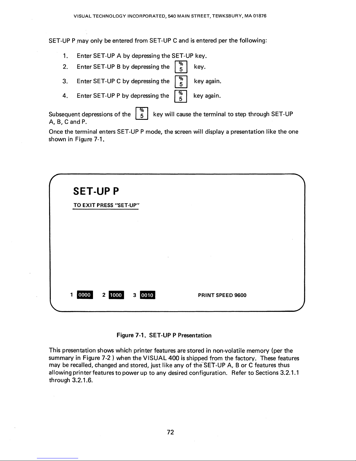
VISUAL
TECHNOLOGY
INCORPORATED,
540
MAIN
STREET,
TEWKSBURY,
MA
01876
SET-UP P
Subsequent depressions
A,
B,
Once the terminal enters SET-UP P mode, the
shown in Figure 7-1.
.may
only
be
entered from SET-UP C and
1.
Enter SET-UP A
2.
Enter SET-UP B
3. Enter SET-UP C
4. Enter SET-UP P by depressing the W key again.
C and
P.
by
depressing the SET-UP key.
will
rnSVo
rnSVo
f%lSVo
cause
screen
by
depressing the W key.
by
depressing the W key again.
of
the I
~
I key
SET-UP P
TO
EXIT
PRESS
"SET·UP"
is
entered per the following:
the terminal
will
display a presentation like the one
to
step through SET-UP
'.
This presentation shows which printer features
summary in Figure 7-2 ) when the
may
be
recalled, changed and stored, just like any
allowing printer features
through 3.2.1.6.
2_
Figure 7-1. SET-UP P Presentation
to
3am
VISUAL
power up
PRINT SPEED 9600
are
stored in non-volatile memory (per the
400
is
shipped from the factory.
of
the
SET-UP A, B or C features thus
to
any desired configuration. Refer
72
These
to
Sections 3.2.1.1
features
Page 83

VISUAL
TECHNOLOGY
INCORPORATED,
540
MAIN
STREET,
TEWKSBURY,
MA
01876
COPY MODE
PRINTER
r----
CONTROLLER
MODE
r-
AUTO
MODE
UNDERLINE
SEQUENCE
1 r I I 1 I
PRINT
21
I I
ON
{ 1 =
O=OFF
{ 1 = ON
O=OFF
{ 1 =
ON
O=OFF
{1
= ON
0=
OFF
II
PARITY
PARITY
BITS
3
'---'--~
SELECT
ENABLE
PER
CHAR.
BUSY
POLARITY
PRINT SPEED
j 1 = EVEN
l 0 = ODD
{ 1 = ON
0=
OFF
{ 1 = 8 BITS
O=7BITS
\
1 = HIGH BUSY
{
0=
LOW BUSY
'-
-LF
,--PRINTER
L----PRINTER
Figure 7-2. SET-UP P Summary
CANCEL
SUPPRESSED
SE
TYPE
BUSY
=
DEL
1
LECT 0 = CAN
{
{
1
{
O=OFF
1 =
{
0=
1 =
XON,XOFF
0=
CONTROL
= ON
NON
FULL
FULL-LINE
LINE
IS
CANCEL
IS
CANCEL
BUFFERED
LINE
BUFFERED
73
Page 84

VISUAL
7.2
SET-UP P FEATURE DEFINITIONS
TECHNOLOGY
INCORPORATED,
540
MAIN
STREET,
TEWKSBURY,
MA
01876
This section details each SET-UP P feature and
7.2.1
Copy Mode
The
setting
explained
of
in
Section 7.3.2.
Resetting Copy
7.2.2
Printer Controller Mode
The
setting
Printer
of
Controller mode
Setting
Controller
7.2.3
Auto
Print Mode
The
setting
Print
mode
of
is
explained
this feature determines
mode
this feature determines
is
explained
whether
will also reset Printer Controller mode.
whether
in
Section 7.3.3.
Printer Controller mode will also
mode
will also reset Copy mode.
this feature determines
in
Section 7.3.4.
whether
their
or
NOTE
or
NOTE
or
effects on
not
Copy
not
Printer Controller mode
set
Copy mode. Resetting Printer
not
Auto
the
terminal and printer.
mode
is
enabled. Copy
Print mode
is
enabled.
mode
is
enabled.
Auto
is
7.2.4
7.2.5
Underline Sequence
This feature
causes underlined data on
plished by sending
by
the
When this feature
when
the
is
applicable
the
data
underline character
is
disabled only
Print Page function
to
the
Print Page
the
screen
character followed by
to
the
printer
the
is
initiated.
Printer Busy
The
setting
to
the
If
the
should be
a
BUSY condition, this feature should be set
of
terminal.
printer
set
The
to
send XOFF/XON
this feature depends
uses a
to
"0",
printer
the
control
busy control line
line state. If
Receiver XON/XOF F SET-UP feature
to
the
command
to
also be underlined on
only. When enabled, this feature
the
backspace character (BS) followed
for every underlined character on
characters
on
how
on
the
screen will be
the
attached
to
indicate a BUSY condition, this feature
the
to
"1",
printer
printer uses XON/XOFF
the
XON/XOFF state.
NOTE
must
be enabled for
host
when
the
printer
is
the
printer. This
the
sent
to
indicates a BUSY
the
busy.
is
screen.
the
to
indicate
terminal
accom-
printer
condition
74
Page 85

VISUAL
TECHNOLOGY
INCORPORATED,
540
MAIN
STREET,
TEWKSBURY,
MA
01876
7.2.6
Printer Type
This feature applies
not
the
terminal will pass
to
Printer Controller mode and Copy mode and determines
the
code
sequences for exiting these modes on
printer.
When this feature
position,
the
is
set
to
the
OFF
Controller and Copy modes will be transmitted
feature will then append
printer. This feature should
When this feature
is
set
to
the
the
CAN
or
DE L code
be
set
to
the
ON
position, no codes
OFF position for full-line buffered printers.
Controller and Copy modes will be transmitted
CANCEL SELECT feature
for F
I
Fa
buffered printers,
is
disregarded. This feature should be
or
printers with no buffer
7.2.7 LF Suppress
This feature determines
printe~.
codes
The
In
will
setting
the
ON
state,
be
sent
to
the
of
this feature depends on how
whether
no
printer.
or
not
LF
codes will be
LF
codes received by
sent
the
Some printers perform a new line function (CR & LF)
case,
the
LF Suppress feature should be enabled
printed data. Some printers perform only
code.
to
the
In
this case,
printer.
the
LF Suppress feature should be disabled
the
carriage return function
ESC
code
sequences for exiting Printer
to
the
printer. The CANCE L SE LECT
to
to
cancel
the
to
the
effect
in
the
sequences for exiting Printer
of
printer. Thus,
set
to
at
all.
the
terminal are
the
printer.
In
the
attached printer reacts
in
response
to
prevent double line spacing
to
to
allow
to
the
the
setting
the
OFF
to
received
the
CR code.
in
response
LF
the
ESC
ON
sent
state,
codes
whether
attached
code
on
of
the
position
to
the
all
CR
codes.
In
on
the
to
the
to
be
or
the
LF
this
CR
sent
7.2.8
Cancel Select
This feature applies
determines
CAN
Controller mode,
Select
DE L code
the
printer
7.2.9
Parity Select and Parity Enable
These
whether
code
or
the
DE L code
or
the
CAN
code
if
the
printer interprets
to
erase its buffer.
two
features determine if parity
Parity enable determines
and
one
disabled
(1) corresponds
Parity select determines
one
(1
and
) corresponds
to
Printer Controller mode and Copy mode, (see Section 7.3.3) and
the
terminal will automatically append and
exit
Copy mode.
if
the
whether
whether
to
immediately following
printer
interprets
DE L as
or
to
parity
the
is
enabled, and if
not
parity
parity enabled.
is
odd
even parity.
the
CAN
as
the
cancel function.
is
enabled. Zero (0) corresponds
or
even. Zero (0) corresponds
Control Sequence
"Cancel
it
is,
whether
transmit
function",
The
to
the
printer
to
exit
and select
cancel function causes
parity
is
to
odd
odd
Printer
or
even.
to
parity
parity
the
the
75
Page 86

VISUAL
TECHNOLOGY
INCORPORATED,
540
MAIN
STREET,
TEWKSBURY,
MA
01876
7.2.10
7.2.11 Busy Polarity
7.2.12
7.3
PRINTER COMMANDS AND MODES
Bits Per Character
This feature determines
code
is
elected,
This feature determines
level
or a true
The
setting
Printer Busy lead high when busy
busy. Check
Print Speed
PRINT SPEED
The
print
printer
19,200
This section describes
In
printed
transmitted.
option
baud).
all
cases, space suppression
line are
the
low level.
of
this feature depends
your
indicates
speed
is
provides
not
whether 7 or 8 data
most
significant
whether
printer
the
changed
for
the
transmitted
bits will be used for each character. If 8 bit
bit
(bit#8)
the
terminal interprets
on
the
and
some
documentation
rate
at
which data will be transmitted
by
depressing
the
same 16 baud rates as
commands
is
performed on a line basis, Le.,
to
the
and
the
printer. Embedded spaces on a line are always
is
printer
printers swing
for
the
rn
modes used
always
being used. Some printers
correct
set
to
space (0).
the
Printer Busy signal as a
their
Printer Busy lead low when
setting
key when
the
communication
to
control an
of
this feature.
to
in
SET-UP P mode.
attached
all
trailing spaces on each
the
attached
interface (50 -
true
"swing"
printer.
printer.
high
their
The
suppression
Space
7.3.1 Print Line/Page Commands
The Print Line/Page
the
operator
minal will use
enabled. XOFF will be
XON will be
be
transmitted
suppress
Table 7-2 summarizes
Commands.
7.3.2
Copy
mode
Copy
When Copy
and
the
from
sent
is
enabled, only CR will be
Mode
allows a variable
mode
printer
commands
the
the
XON/XOFF
to
the
at
the
selected
the
is
entered,
simultaneously.
is
keyboard. When
sent
to
host
on conclusion
various ways
number
all
NOTE
not
applicable
may be initiated via remote
synchronization codes if
the
host
print
rate a'nd be ended with
sent
to
of
data
received
in
Printer Controller
the
Print Line/Page function
upon
initiation
of
the
Print Line/Page function. Each line will
to
the
printer).
obtain
lines
to
by
hard
copy
be
output
the
terminal will be
or
Copy
command
is
the
Receiver
of
a Print Line/Page
the
CR/LF
via
the
Print
to
the
printer.
sent
mode.
from
the
host
initiated
XON/XOFF
codes. (If
Page/Line
to
the
function,
the
screen
or
ter-
feature
and
LF
by
is
76
Page 87

VISUAL
TECHNOLOGY
INCORPORATED, 540
MAIN
STREET, TEWKSBURY,
MA
01876
7.3.3
Printer
Controller
Printer Controller
without
printer
rate
XON/OFF
7.3.4
Auto
When
to
CR/LF
that
Auto
be
affecting
by using
the
Print
Print
Auto
output
codes
to
mode
nization codes
mode
the
the
XON/XOFF
printer
can accept.
be used.
Mode
allows a variable
Print
mode
to
the
printer. Each line
or
the
CR
will be used
Mode
allows
the
host
terminal screen.
synchronization codes
The
number
is
entered,
code
in
a received LF code causes
as
the
LF
Auto
Print Mode. See Table 7.2.
to
pass
all
data
In
effect,
through
the
terminal acts as a
to
limit
the
the
Receiver XON/XO F F feature
of
lines
to
be
transmitted
to
the
output
printer
to
the
line containing
will be
suppress feature dictates.
terminal
controller
transmitted
must
be enabled for
the
printer.
ended
The
XON/XOFF
to
with
the
for
data
the
printer
the
to
a
cursor
the
synchro-
77
Page 88

VISUAL
TECHNOLOGY
INCORPORATED, 540
MAIN
STREET,
TEWKSBURY,
MA
01876
SUMMARY
OF PRINT COMMANDS
Function From Keyboard
Print
Print
Page
Cu
rsor
PRINT
Key
Echoed Sequence
Line
Print
Line
Echoed Sequence
lip"
Print
lip"
Lines
to
"Q"
Echoed Sequence
TABLE
Remote
ESC
ESC
ESC
ESC
P;
Qi
7-2
[ i
[ ? 1 i
[ ? 1;
[ ? 1;
Pi
AND
MODES
Action
XOFF
code sent
to
suspend transmission.
Contents
ted
codes
to
printer
or
of
screen
only
with
CRafter
line. XON code sent
to
resume
Print
XOFF code sent
transmission once
Page
function complete.
to
suspend transmission.
of
Contents
mitted
codes
XON code sent
cursor line trans-
to
printer
or
only
CR
with
after line.
to
host
resume transmission once
Print
Line function complete.
XOFF
code sent
to
suspend transmission.
of
line
Contents
mitted
codes
to
or
printer
only
XON code sent
resume
transmission once
lip"
with
CR
after line.
to
host
Print Line function complete. Line P
is
in decimal
notation between the
of
1 and 24.
XOFF
Code sent
to
suspend transmission. Con-
of
lines
lip"
tents
"Q"
transmitted
with
CR/LF
CR
after
each
code sent
to
transmission once
tion
complete. Line P and
Q
are
both in decimal notation
between the
through
to
codes
or
line. XON
host
to
Print
limits
of
host
to
transmitCR/LF
each
to
host
host
to
CR/LF
to
host
to
trans-
CR/LF
to
limits
host
to
printer
only
resume
func-
1 and 24.
78
Page 89

VISUAL
TECHNOLOGY
INCORPORATED, 540
MAIN
STREET,
TEWKSBURY,
MA
01876
Function
Enter Copy
Mode
SUMMARY
From Keyboard Remote
FUNCTION PRINT
or
change
OF
in
PRINT
SET-UP P
Exit
Copy
Mode
FUNCTION PRINT
or
change in
SET-UP P
Enter Printer Echoed Sequence
Controller
or
change in through terminal
Mode SET-UP P
Exit
Printer
Controller
Mode
Auto
Enter
Print
Mode
Echoed Sequence
or
change in Controller mode, and auto-
SET-UP P
Echoed Sequence
or
change in
SET-UP P
Exit
Print
Auto
Mode
Echoed Sequence
or
change in
SET-UP
P.
TABLE
7-2
COMMANDS
ESC
[ ? 7 i
ESC
[ ? 6 i Terminal exits Copy mode
ESC
[ 5 i Data sent
ESC
[ 4 i Terminal exits
ESC
[ ? 5 i
ESC
[ ? 4 i
AND
MODES (Cont.)
Received data displayed on
screen
taneously.
host in response
busy. XON code sent
host in response
not
and automatically appends
the
CANCE L
dictates.
TYPE
will
XOFF
response
XON code sent
response
busy.
matically appends the CAN
or
SE
the PRINTER TYPE feature
is
appended.
On
code sent
of
with
line. XON code sent
after
Terminal exits
mode.
Action
and sent
to
XOFF
busy.
CAN
or
DE
L code
SE
LECT feature
If
the PRINTER
feature
be
appended.
from
is
host
code sent
to
printer
to
to
printer
printer
DEL
code
as
the CANCEL
LECT featu
ON, no code
receipt
re
will
of
LF
to
host. Contents
line transmitted
CR/LF
line
or
only
is
transmitted.
Auto
printer simul-
code sent
to
printer
to
to
printer
as
the
ON, no code
passed
to
printer.
to
host in
busy.
host in
not
dictates.
If
be
code
XOFF
to
printer
CR
after-
to
host
Print
to
79
Page 90

Page 91

8.1
GENERAL
VISUAL
TECHNOLOGY
INCORPORATED, 540
8.
PAGING
MAIN
STREET,
OPTION
TEWKSBURY,
MA
01876
The standard
page
of
The
Paging
different
1.
2. Five
Regardless
user may
VISUAL
data may
be
Option provides
forms:
Three total
total
of
whether the
select either
400
arranged
pages
pages
an
80
8.2 MEMORY ORGANIZATION
The contents
of
display memory
terminal's screen being a 24 line
up
or
down past the
at
anyone
Figure
8-1
time.
illustrates the memory organization
window
400 termfnals. Upon power-up
operator.
When operating in
Block mode and the document
nurnbers (lines 1-24 currently visible), attempts
result in no action. Conversely,
(lines
49-72 visible on three-page units and lines 97-120 visible on five-page units), attempts
to
move the document up
has
a display memory capacity equal
as
24 lines
for
added
of
display memory (72 lines)
of
display memory (120 lines)
VISUAL
or
132 column display format.
can
"window"
to
allow the user
or
if
the document
further
will
by
80 columns
pages
of
display memory and
400
is
configured
be
thought
to
the document. The document may be moved
to
of
reset,
page
number one (lines 1-24)
to
result in no action.
of
as
view any 24 line segment
both three-page and five-page
is
moved
move the document
is
moved
to
one
page
of
data. The
or
24 lines
as
a three-page
by
132 columns.
is
available in
or
five-page
a large multi-line document,
of
the document
VISUAL
will
be
visible
down
to
its lower-most line
down
to
its upper-most line numbers
further
two
unit,
with
to
the
the
the
will
When operating in Character mode,
Format Effectors and Editing Functions
Format Effectors are commands
any new
lines
that
are
previously existed on these lines. Table
movement
Editor
i.e., any new
lists
Editor
The
following
of
the document
Functions are commands
lines
that
Functions which may
example contrasts non-destructive document movement
Functions, and destructive document movement
assumes
the
VISUAL
scrolled
if
are scrolled
400
is
in Character mode.
it
is
very
that
into
cause
view
important
as
they
relate
"destructive" movement
of
the operator
8-1
lists Format Effectors which
to
to
will
received in Character mode.
that
cause
"non-destructive" movement
into
view
of
the operator
cause
non-destructive movement
caused
by
81
note
the
distinction between
movement
be
will
of
of
blank
lines
not
be
of
the document.
caused
the document.
the document, i.e.,
even
if
data
cause
destructive
of
the document,
altered. Table 8-2
by
Editor
Format Effectors. The example
Page 92

.--
- - - - - - -
VISUAL
TECHNOLOGY INCORPORATED, 540
---.
__
10----
LI
N E 1
MAIN
STREET, TEWKSBURY,
..
.-----
MA
01876
------
~---
PAGE 1
-
-----
PAGE 2
PAGE 3
...........
---L1NE2
..
..
L1NE4
L1NE7
4
8
2
PAGE 1
---.------
PAGE 2
--
PAGE 3
..
3-PAGE
NOTE
The
displayed 24 lines.-
dotted
UNIT
lines indicate
the
currently
L1NE9
LINE
6
1 20
..
...
5-PAGE
PAGE 4
PAGE 5
UNIT
Figure 8-1. Paging
Memory
82
Organization
Page 93

VISUAL
TECHNOLOGY
INCORPORATED, 540
MAIN
STREET,
TEWKSBURY,
MA
01876
TABLE
FORMAT
EFFECTORS WHICH CAUSE MOVEMENT OF THE DOCUMENT
Format Effector Code
line
Feed
Index
Backspace
Reverse
Index
Horizontal Tab*
Form
Feed
Space**
Entry
of
Any**
8-1
Octal
Equivalent
LF 012
ESC
BS
ESC
HT
FF
SP
D
M
033 104
008
033 115
010
014
040
Displayable Character
* Autowrap mode must be set
**
Autowrap
to
cause destructive movement
mode must be set and
to
cause destructive movement
the
cursor must be on
of
the
document.
TABLE
8-2
of
the
last column
the
document.
of
the
line
EDITOR FUNCTIONS WHICH CAUSE MOVEMENT OF THE DOCUMENT
Editor
Next
Function
Line*
Previous Line*
Cursor
Cursor
Cursor
Cursor
Left*
Right*
Up*
Down*
Cursor Horizontal Tab*
Cursor Back Tab*
Next Page**
Previous Page**
Scroll
Scroll
**These Editor Functions will always cause
Down*
*
Up**
*These Editor Functions will cause
is
set, see Section 8.3.1.
the
document
Code Octal
ESC [ Pn
ESC [ Pn
ESC [ Pn
ESC [ Pn
ESC [ Pn
ESC [ Pn
ESC [ Pn
ESC [ Pn
ESC [ Pn
ESC [ Pn
ESC [ Pn
ESC [ Pn
the
E 033 133 P n 1 05
F 033 133
D
033 133
C 033 133
A 033 133
B
033 133
I 033 133 P n
Z 033 133
U
V
033 133
033133
T 033 133
S
to
move only if Edit Boundary mode
document
to
033
move. See Section 8.4.
133
Pn
Pn
Pn
Pn
Pn
Pn
Pn
Pn
Pn
Pn
106
104
103
101
102
111
132
125
126
126
123
83
Page 94

VISUAL
Example 1
The document
gram
1)
and the cursor
TECHNOLOGY
is
positioned
is
on
INCORPORATED,
so
that
page
the
last line
540
one
of
MAIN
STREET,
is
currently visible
page
one (line 24).
TEWKSBURY,
to
the operator
MA
01876
(see
Dia-
LINE
1
r-------
•
F---------
PAGE 1
PAGE 2
PAGE 3
---
DIAGRAM
1
LINE
72
If
a Line
The visible effect on the
will
I n the aforementioned example,
instead
Feed
code (Format Effector)
1.
The document moves up destructively one line.
2. Line number 25 becomes a blank line
screen.
screen
come
into
view on the last line
of
the Line
1.
. The document moves up non-destructively one line.
2. Line number 25
altered.
Feed
Code, the
is
is
scrolled
that
of
if
a Cursor Down command
resu
is
now
received
all lines
the screen.
It
is:
into
view
84
by
the
terminal the result
and
is
scrolled on
will
scroll-up one line
of
the operator. No data on line 25
to
(Editor
the last line
and
a new blank line
Function)
is:
of
the
is
received
is
Page 95

VISUAL
8.3 ADDITIONAL MODES
There
are
not
do
TECHNOLOGY
two
modes which concern the operation
appear in
the
INCORPORATED,
standard
VISUAL
540
MAIN
STREET,
400. These modes are:
of
VISUAL
TEWKSBURY,
MA
01876
400
multi-page units which
8.3.1
Edit
Boundary Mode,
Edit
Boundary mode provides a choice
document
When reset,
rently displayed
to
affect
The
Edit
board in
procedure should
To
set/reset
should
or
the
Editor
Boundary mode may
SET-UP mode.
1.
Depress the SET-UP key
2. Depress the
of
A one (1) corresponds
ary mode reset.
be
used:
Ps
= 19
only
the
currently
Edit
Boundary mode allows certain
24
lines. When set,
entire document.
Functions
group 7. Depress
Edit
that
To
be
followed:
I
~
Boundary mode remotely, the
are
affected
be
set
set/reset
I key
the
displayed
or
to
to
to
for
having certain
24
lines.
Editor
Edit
Boundary mode allows certain
by
Edit
Boundary mode are listed in Table 8-3.
reset remotely via
Edit
Boundary mode
enter SET-UP mode.
enter SET-UP B mode. Position the cursor over
I
~
I key
to
alternately set/reset
Edit
Boundary mode
following
Editor
Functions
control
sequence
from
set
and a zero (0)
set/reset mode
Functions affect the entire
to
affect
the keyboard, the
only
Editor
or
Edit
control
Functions
from
Boundary mode.
to
Edit
the cur-
the key-
following
bit
3
Bound-
sequences
Set
Edit
Reset
Page
8.3.2
This
When
displayed
display memory.
Page
the transmittable
Page
in
SET-UP mode.
cedure should
Transfer Mode,
is a VISUAL
Page
24
Transfer mode
Transfer mode may
Boundary mode
Edit
Boundary mode
Technology Incorporated defined mode
Transfer mode
lines. When
is
used
portion
To
set/reset
be
followed:
ESC
[19h
ESC
[ 19 Q
Ps
= 161
is
set, the terminal may transmit data
Page
Transfer mode
in
conjunction
of
memory.
be
set
or
Page
(See
reset remotely via
Transfer mode
is
reset, the terminal may
with
the other transmission modes
Section 6.0.)
control
from
that
applies
from
sequence
the keyboard,
to
Block mode only.
only
the
currently
transmit
or
from
the
the
to
condition
the keyboard
following
entire
pro-
85
Page 96

VISUAL
TECHNOLOGY
INCORPORATED,
540
MAIN
STREET,
TEWKSBURY,
MA
01876
EDITOR
Editor
FUNCTIONS
Function Code Sequence
I nsert Character
Delete Character
Insert Line
Delete Line
Entry
of
Data
with
I nsert Replace Mode Set
Erase
in Area
Erase
in Display
Erase
in Field
Erase
Character
Cursor Back Tab
Cursor Horizontal Tab
TABLE
AFFECTED
ESC [ Pn
ESC [ Pn
ESC [ Pn
ESC [ Pn
ESC [ Ps
ESC [ Ps
ESC [ Ps
ESC
ESC [ Pn
ESC [ Pn
8-3
BY
EDIT
BOUNDARY
@
P 033 133
L 033 133
M 033 133
0 033 133
J
N
[ Pn.X
Z 033 133
I
MODE
Octal Equivalent
033 133
033133
033 133
033 133
033133Pn
Pn
Pn
Pn
Pn
Ps
Ps
Ps
Pn
Pn
100
120
114
115
117
112
116
130
132
111
Cursor
Left
Cursor Right
Cursor
Up
Cursor Down
Cursor
Next
Line
Cursor Previous Line
ESC [ Pn
ESC [ Pn
ESC [ Pn
ESC [ Pn
ESC [ Pn
ESC [ Pn
D 033 133
C
033 133
A 033 133
B 033 133
E
033 133
F 033 133
Pn
Pn
Pn
Pn
Pn
Pn
104
103
101
102
105
106
86
Page 97

VISUAL
1.
TECHNOLOGY
Depress
the
INCORPORATED,
SET-UP
key
540
MAIN
STREET,
to
enter SET-UP A mode.
TEWKSBURY,
MA
01876
To
should
8.4
ADDITIONAL
There
page
are:
8.4.1
This command
tion.
screen.
page
position
2. Depress the
of
group 9. Depress
A one (1) corresponds
mode reset.
set/reset
Set
Reset
terminals which
Scroll-Up,
The visible effect on
units and lines 97-120 on five-page units) all Scroll
Page
be
used:
Page
Transfer mode
Page
Transfer Mode
COMMANDS
are
five additional commands which concern
ESC [ Pn
causes
If
the
top
of
the cursor on
I
~
I key
to
enter SET-UP B mode. Position the cursor over
the
I
~
I key
to
Page
Transfer mode set and a zero (0)
Transfer mode remotely,
ESC [ 161
ESC [ 161
do
not
appear in the standard
S
the
24
document
lines
the
the
of
the document
screen
screen
to
move up
is
that
is
not
to
the
following
data
are
currently
altered.
alternately set/reset
Pn
will
Page
Transfer mode.
to
set/reset mode
h
Q
the
operation
VISUAL
lines.
move up
400
Pn
is
specified in decimal nota-
from
displayed (lines 49-72 on three-
Up
commands are ignored. The
control
of
VISUAL
terminal. The commands
the
bottom
Page
Transfer
sequences
400
multi-
of
bit
the
1
8.4.2 Scroll
This command
down
Pn
data
will
are
currently
of
the cursor on
8.4.3
Next
This command
of
the Pn'th
notation.
will
be
moved up
Next
The
Down,
lines.
move
Page,
If
Page
ESC [ Pn
is
the
Pn
is
specified in decimal
down
displayed (lines 1-24) all Scroll Down commands are ignored. The position
the
screen
ESC [ Pn
causes
page
following
the
currently
to
the
command
T
opposite
from
the
is
U
the
document
the
displayed
Pn'th
can
of
the Scroll Up command and
top
of
the screen.
not
altered.
to
currently
window
page
following
never move
notation.
move up
displayed
is
the
The visible effect on
If
the
(to
window.
not
on a
the
page
document
causes
bottom
higher numbered lines)
Pn
page
boundary
on which
beyond
the
document
the
24
lines
of
is
specified in decimal
the
the
bottom
the
top
page.
screen
the document
to
the
document
lines reside.
to
move
is
that
beginning
87
Page 98

VISUAL
TECHNOLOGY
INCORPORATED,
540
MAIN
STREET,
TEWKSBURY,
MA
01876
8.4.4 Previous
This command
ning
notation.
be
The Previous
8.4.5 Print
This command
causes
8.5
ADDITIONAL
of
moved
Page,
ESC [ Pn
the
All,
Pn'th
If
the
down
Page
ESC
causes
is
the document
page
preceding
currently
to
the Pn'th
command
[ ? 9 i
functional
the entire document
KEYBOARD
V
displayed
page
can
only
to
be transferred
CONTROLS
The user may perform the Scroll Up, Scroll
commands
from
the
keyboard
by
the additional keyboard controls on
8.6
MODIFIED
There
minals
COMMAND
are
three commands which
as
opposed
OPERATIONS
to
the standard
8.6.1 Absolute Cursor Positioning Command
to
move
down
(to
the
currently
window
preceding
never move
if
the
Buffered Printer I nterface
lower numbered lines)
displayed window.
is
not
on a
page
the
page
on which the
the
document beyond
to
an
attached printer.
Down,
Next
Page,
Pn
is
boundary
top
to
Option
Previous
specified in decimal
the
lines reside.
the
Page
to
the begin-
document
bottom
is
installed and
and Home
page.
depressing the appropriate keys. Table 8-4 summarizes
VISUAL
cause a different
VISUAL
400
mUlti-page terminals.
action on
400
terminal. These commands are:
ESC
[ y ; x H
VISUAL
400
mUlti-page ter-
will
This command
24 lines
as
The above sequence
specified
is
used
for
positioning
described in Section 5.3.2.
will
position the cursor
by
"x".
Both line and column parameters
the
cursor anywhere
to
8.6.2 Horizontal and Vertical Position Command
This command
The above sequence
specified
mand may
from
view.
8.6.3 Form
This
control
page,
and home
8.6.4 What
This command
VISUAL
displayed
the response
is
used
to
position the cursor anywhere
will
position
by
"x".
Both line and column parameters
cause
the cursor
It
is
recommended
Feed
(octal 014)
code
will
the
cursor.
is
Cursor Location Relative
will
cause
400
Reference Manual provided
24
lines.
will
be
If
as
to
move
move the document
the terminal
the cursor
follows:
the
cursor
off
that
the keyboard
to
to
is
not
to
the
currently
to
the beginning
the
Screen?
respond
the
cursor
positioned
within
the line specified
are
in decimal notation.
ESC
[ y ; x f
within
the
line specified
are
in decimal notation. This com-
by
the entire display memory.
by
displayed 24 lines and thus disappear
be
locked while the cursor
of
the next
ESC
[ 6 n
as
indicated in Section 5.3.9
is
positioned
within
the
currently
the currently displayed
"y"
and
the
column
"y"
and the column
is
off
screen.
page,
erase
the
of
the
within
the
currently
displayed 24 lines
88
Page 99

VISUAL
TECHNOLOGY
INCORPORATED,
540
MAIN
STREET,
TEWKSBURY,
MA
01876
Depressed
Keys
FUNCTION
FUNCTION
FUNCTION
FUNCTION
FUNCTION
with
with
with
with
with
ADDITIONAL
~
[!]
B
\ .... \
IHOMEI
TABLE
KEYBOARD CONTROLS
Code
Transmitted in Mode
Character Mode Mode
ESC
ESC
ESC
ESC
ESC
ESC
8-4
Sequence
[T
[S
[V
[U
[99
V
[H
Action
Scroll Down
Scroll Up
Previous
Next
Cursor
Position
will
Caused
or
if
Sequence Echoed
Page
Page
goes
of
also
be
in Block
in Character
to
Home
Page
displayed.
1.
Page
1
*SHIFTwith
*SH
I FT
*SHIFT
*SH I FT
*SH I FT
*These keyboard controls are local
Character mode. These controls allow
transmitting any codes.
with
with
with
with
~
[!]
B
\ .... 1
\
HOMEI
only
None
None
None
None
None
and are provided mainly for
the
user
to
move
the
document
Scroll Down
Scroll Up
Previous
Page
Next
Cursor
Position
will
the
user
up and down locally
also
who
goes
is
operating
Page
to
of
Page
be
displayed.
Home
1.
Page
in
without
1
89
Page 100

VISUAL
TECHNOLOGY
INCORPORATED,
540
MAIN
STREET, TEWKSBURY,
MA
01876
In
both
responses, y
and y = 1-120 on five
notation.
8.6.5 What
is
Cursor Location Relative
This command
The response
ESC
y
is
the current line number
page
units) and x
[y
from
; x R
Cursor Position
Cursor
lower
the
is
positioned
line number than
cu
rrently displayed
on
24 lines.
Cursor
higher line number than
the
is
positioned
currently
on
displayed
24 lines.
is
the current line number
page
units) and x
to
will
cause
the terminal
the terminal
is
the
column position. Both y and x are in decimal notation.
of
will
be:
the
cursor (y = 1-72 on three-page units and 1-120 on five-
a
a
of
the cursor
is
the
column position. Both y and x are in decimal
the Entire Memory?
to
respond
with
the
Terminal
ESC
ESC
(y
absolute position
Response
[<
y ; x R
[>
y ; x R
= 1-72 on three-page units
ESC
[ ? n
of
the
cursor.
8.7
RECEIVING
When a mUlti-page
appear
8.8
OPERATION
DATA
VISUAL
400
terminal
zontal and Vertical Position command
into
a memory
from
area
not
currently
displayed. By using this command,
the operators view and no screen scrolling
ing throughput.
It
is
also suggested
(see
3.2.3.41,3.2.3.44,5.4.2
not
interfere
with
that
prior
the
incoming data.
to
sending any data
of
the
VISUAL
unlocked.
RESTRICTIONS
There
5.3.1
restriction
the
and
is
one notable restriction concerning the Scrolling Region command
of
VISUAL
is
Scrolling Region command
the
Scrolling Region command is issued,
that
400
Reference Manual) on
page
number one (lines 1-24) should be
is
issued. I f
is
receiving data,
be
used
400
After
the
VISUAL
page
loss
it
to
address
to
the
will
occur thus significantly increas-
the terminal
Reference Manual)
data
is
received the keyboard
400
mUlti-page terminals. The
currently
number one
of
data may occur.
is
suggested
cursor
the
is
not
that
the
Hori-
if
data
is
to
be
written
the
cursor
will
dis-
keyboard be locked
so
the
operator does
can
be
(see
Section
displayed whenever
currently
displayed
90
 Loading...