


TIMECORE
MANUAL
© VISUAL PRODUCTIONS BV WWW.VISUALPRODUCTIONS.NL

Contents
1 Introduction 5
2 Protocols 8
3 Quickstart 11
4 Setting up 16
5 Network 18
6 vManager 21
7 Show Control 24
8 Monitors 28
9 Settings 30
Appendices 36
A Templates 37
B Trigger Types 38
C Task Types 46
D API 52
2

c
2014-2017 Visual Productions BV. All rights reserved.
No parts of this work may be reproduced in any form or by any means - graphic,
electronic, or mechanical, including photocopying, recording, taping, or information storage and retrieval systems - without the written permission of the
publisher.
While every precaution has been taken in the preparation of this document,
the publisher and the author assume no responsibility for errors or omissions,
or for damages resulting from the use of information contained in this document or from the use of programs and source code that may accompany it. In
no event shall the publisher and the author be liable for any loss of profit or
any other commercial damage caused or alleged to have been caused directly or
indirectly by this document.
Due to the dynamic nature of product design, the information contained in
this document is subject to change without notice. Revisions of this information or new editions may be issued to incorporate such changes.
Products that are referred to in this document may be either trademarks and/or
registered trademarks of the respective owners. The publisher and the author
make no claim to these trademarks.
3

Declaration of Conformity
We, manufacturer Visual Productions BV, herby declare under sole responsibility,
that the following device:
TimeCore
Conforms to the following EC Directives, including all amendments:
EMC Directive 2004/108/EG
And the following harmonized standards have been applied:
NEN-EN-IEC 61000-6-1:2007
NEN-EN-IEC 61000-6-3:2007
Full name and identication of the person responsible for product quality and
accordance with standards on behalf of the manufacturer
Date: Place:
May 8th, 2017 Haarlem, The Netherlands
ing. Maarten Engels
Managing Director
Visual Productions BV
VISUAL PRODUCTIONS BV
IZAAK ENSCHEDEWEG 38A
NL-2031CR HAARLEM
THE NETHERLANDS
TEL +31 (0)23 551 20 30
WWW.VISUALPRODUCTIONS.NL
INFO@VISUALPRODUCTIONS.NL
ABN-AMRO BANK 53.22.22.261
BIC ABNANL2A
IBAN NL18ABNA0532222261
VAT NL851328477B01
COC 54497795

Chapter 1
Introduction
The TimeCore is a solid-state device for handling timecode. It is intended to
be used for entertainment shows at events, concerts, festivals and in themed
environments. The TimeCore will help in keeping the various show elements
like sound, lighting, video, laser and special FX synchronised.
Figure 1.1: TimeCore
The TimeCore can generate timecode, it can convert it between different
protocols and it can display any received timecode on its display. The unit
features inbuilt web-server; this web-interface allows the user to configure the
unit. The web-interface also enables other non-timecode protocols like UDP,
OSC and sACN to be linked to certain timecode events. The TimeCore can be
the bridge between timecode and other non-timecode show equipment such as
video players, relays and dimmers.
The TimeCore features a rich suite of protocols that include the two most
popular timecodes in show business SMPTE and MTC. Furthermore, it has ArtNet timecode implemented, which has the advantage of being network-based.
This document discusses setting up the device and programming its internal
software functions.
5

1.1 Features
The feature set of the TimeCore includes:
• Ethernet port
• Programming via web-interface
• SMPTE
• MTC
• MIDI, MSC, MMC
• OSC, UDP, TCP
• Art-Net (data & timecode)
• sACN
• Large 7-segment LED display
• 2x user-definable push-button
• 9-24V DC 500mA (PSU included)
• Power over Ethernet (class I)
• Desktop or DIN Rail mounted (optional adapter)
• Operating temperature -20C to +50C (-4F to 122F)
• Compliance EN55103-1 EN55103-2
• Bundled with vManager and Kiosc software
1.2 What’s in the box?
The TimeCore packaging contains the following items (see figure 1.2):
• Info card
• TimeCore
• Power supply (inc. internation plug set)
6

Figure 1.2: TimeCore box contents
1.3 Saving data to memory
This manual will describe how to configure the TimeCore and program actions
tasks, etc. The unit’s web-interface is used for editing these kinds of elements.
When changes are made, these changes are directly stored in the RAM memory
of the TimeCore and the programming will directly influence the behaviour of
the unit. RAM memory is, however, volatile and its content will be lost through
a power cycle. For this reason the TimeCore will copy any changes in the RAM
memory to its onboard flash memory. Flash memory retains its data even when
not powered. The TimeCore will load all its data back from the flash memory
upon startup.
This memory copy process is conducted automatically by the TimeCore and
should not be of any concern of the user. One point of consideration is, however, that after making a change the unit should be given time to perform the
copy to flash. As a rule of thumb, do not disconnect the power from the device
within 30 seconds from making a programming change.
1.4 Further Help
If, after reading this manual, you have further questions then please consult
the online forum at http://forum.visualproductions.nl for more technical
support.
7

Chapter 2
Protocols
The TimeCore is fitted with several communication ports and supports various
protocols. This chapter describes these protocols and to which extent they are
implemented in the TimeCore
2.1 SMPTE
SMPTE is timecode signal which can be used to synchronise audio, video, lighting and other show equipment. The TimeCore supports receiving and transmitting SMPTE that is transferred as an audio signal, also know as LTC timecode.
2.2 MIDI
The MIDI protocol is intended for inter-connecting musical devices such as synthesisers and sequencers. Furthermore, this protocol is also very suitable to
send triggers from one device to another and is often used to synchronise audio,
video and lighting equipment. There is also a large collection of MIDI control surfaces available; user-interface consoles with knobs, (motorised-)faders,
rotary-encoders, etc.
The TimeCore is fitted with a MIDI input and MIDI output port. It supports
receiving and sending MIDI messages like NoteOn, NoteOff, ControlChange and
ProgramChange.
2.2.1 MTC
MIDI Timecode (MTC) is the timecode signal which is embedded into MIDI.
The TimeCore supports receiving and transmitting MTC. It is not recommended
to combine the use of MTC with ordinary MIDI as MTC consumes the bandwidth of the MIDI connection.
2.2.2 MMC
MIDI Machine Control (MMC) is part of the MIDI protocol. It defines special
messages for controlling audio equipment such as multi-track recorders. The
8

TimeCore supports the sending of MMC commands; please refer to page 47.
2.2.3 MSC
MIDI Show Control (MSC) is an extension of the MIDI protocol. It comprises
of commands for synchronising show equipment like lighting, video and audio
devices. The TimeCore supports sending MSC commands; please refer to page
48.
2.3 Art-Net
The Art-Net protocol primarily transfers DMX-512 data over Ethernet. The
high bandwidth of an Ethernet connection allows Art-Net to transfer up to 256
universes. The data sent out for Art-Net does put a certain load on the network,
therefore it is recommended to disable Art-Net when not in use.
Additional to transmitting DMX-512 data, Art-Net can also be used for transferring timecode information for equipment synchronisation.
The TimeCore supports sending and receiving of Art-Net timecode as well as
Art-Net data.
2.4 sACN
The streaming Architecture of Control Networks (sACN) protocol uses a method
of transporting DMX-512 information over TCP/IP networks. The protocol is
specified in the ANSI E1.31-2009 standard.
The sACN protocol supports multi-cast in order to take efficient use of the
network’s bandwidth.
The TimeCore supports sending and receiving of one sACN universe.
2.5 TCP
The Transmission Control Protocol (TCP) is a core protocol of the Internet
Protocol Suite. It is used for its reliable, ordered and error checked delivery
of a stream of bytes between applications and hosts over IP networks. It is
considered ’reliable’ because the protocol itself checks to see if everything that
was transmitted was delivered at the receiving end. TCP allows for the retransmission of lost packets, thereby making sure that all data transmitted is received.
The TimeCore supports reception of TCP message.
9

2.6 UDP
User Datagram Protocol (UDP) is a simple protocol for sending messages across
the network. It is supported by various media devices like video projectors and
Show Controllers. It does not incorporate error checking, therefor it is faster
than TCP but less reliable.
There are two ways how to have the TimeCore respond to incoming UDP
messages. The API (see page 53) makes typical TimeCore functions available
through UDP. Furthermore, custom messages can be programmed in the Show
Control page (see page 24). This is also the place where to program outgoing
UDP messages.
2.7 OSC
Open Sound Control (OSC) is a protocol for communicating between software
and various multi-media type devices. OSC uses the network to send and receive messages, it can contain MIDI and custom information. There are apps
available for creating custom-made user interfaces on iOS (iPod, iPhone, iPad)
and Android. These tools allow to program fool-proof user-interfaces for controlling the device. E.g. TouchOSC from http://hexler.net/software/touchosc.
There is a TouchOSC layout available from http://www.visualproductions.
nl/products/quadcore.html that is configured to control the Playbacks of the
TimeCore.
There are two ways how to have the TimeCore respond to incoming OSC messages. Firstly, the API (see page 52) makes typical TimeCore functions available
through OSC. Secondly, custom messages can be programmed in the Show Control page (see page 24).
2.8 DHCP
The Dynamic Host Configuration Protocol (DHCP) is a standardised network
protocol used on Internet Protocol (IP) networks for dynamically distributing
network configuration parameters, such as IP addresses.
The TimeCore is a DHCP client.
10

Chapter 3
Quickstart
This chapter provides step by step tutorials on how to program your TimeCore
for some typical tasks:
• SMPTE Generator
• SMPTE Display
• MTC to Art-Net Converter
3.1 SMPTE Generator
This tutorial shows how to use the TimeCore to generate timecode and send it
out via SMPTE.
1. Setup network and connections
Connect the TimeCore and the computer to a network with DHCP server.
11

2. Discover the TimeCore
Install and run the vManager software to detect the TimeCore on the
network. Select the unit in vManager and press the ’Browse’ button.
3. Add template
Go to the Show Control page and select the ’Buttons ->Timecode’
template. Press the ’Add >>’ button in the lower left corner of the
screen.
4. Configure timecode input
Go to the TimeCore Settings page and set the timecode input to ’Internal’.
12

5. Configure timecode output
Go to the TimeCore Settings page and enable SMPTE in the timecode
output.
Pressing the left push-button will now start the timecode.
3.2 SMPTE Display
This example sets up the TimeCore to receive SMPTE and display the timecode
on its display:
1. Setup network and connections
Connect the TimeCore and the computer to a network with DHCP server.
2. Discover the TimeCore
Install and run the vManager software to detect the TimeCore on the
network. Select the unit in vManager and press the ’Browse’ button.
13
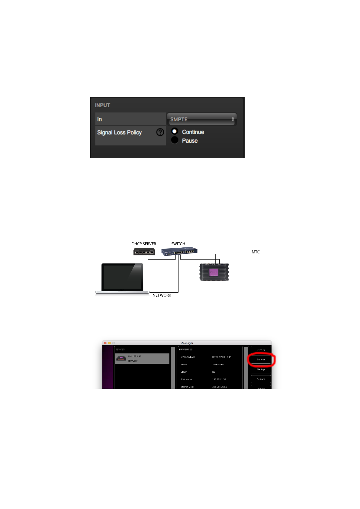
3. Configure timecode input
Go to the TimeCore Settings page and set the timecode input to ’SMPTE’.
The TimeCore will now show the received SMPTE timecode on the display.
3.3 MTC to Art-Net Converter
This example show how to use the TimeCore to convert MIDI timecode to
Art-Net timecode:
1. Setup network and connections
Connect the TimeCore and the computer to a network with DHCP server.
2. Discover the TimeCore
Install and run the vManager software to detect the TimeCore on the
network. Select the unit in vManager and press the ’Browse’ button.
14

3. Configure timecode input
Go to the TimeCore Settings page and set the timecode input to ’MTC’.
4. Configure timecode output
Go to the TimeCore Settings page and enable Art-Net in the timecode
output.
The TimeCore will now convert the incoming MTC to Art-Net.
15

Chapter 4
Setting up
This chapter discusses how to set up the TimeCore.
4.1 Mounting
The device can be placed desktop or it can be DIN Rail mounted. The device
is prepared for DIN Rail mounting by using the ’DIN rail holder TSH 35’ from
Bopla (Product no. 22035000).
Figure 4.1: Bopla DIN rail adapter
This adapter is - amongst others - available from:
• Farnell / Newark (order code 4189991)
• Conrad (order code 539775 - 89)
• Distrelec (order code 300060)
4.2 Kensington Lock
The device can be secured by using a Kensington style laptop lock.
16

Figure 4.2: Kensington lock
4.3 Power
The TimeCore requires a DC power supply between 9 and 24 Volt with a minimum of 500mA. The 2,1 mm DC connector is center-positive. The TimeCore
is also Power-over-Ethernet (PoE) enabled. It requires PoE Class I.
Figure 4.3: DC polarity
17
Chapter 5
Network
The TimeCore is a network capable device. A network connection between
between a computer and the unit is required to configure and program the
TimeCore, however, once the device is programmed then it is not necessary
anymore for the TimeCore to be connected to an Ethernet network.
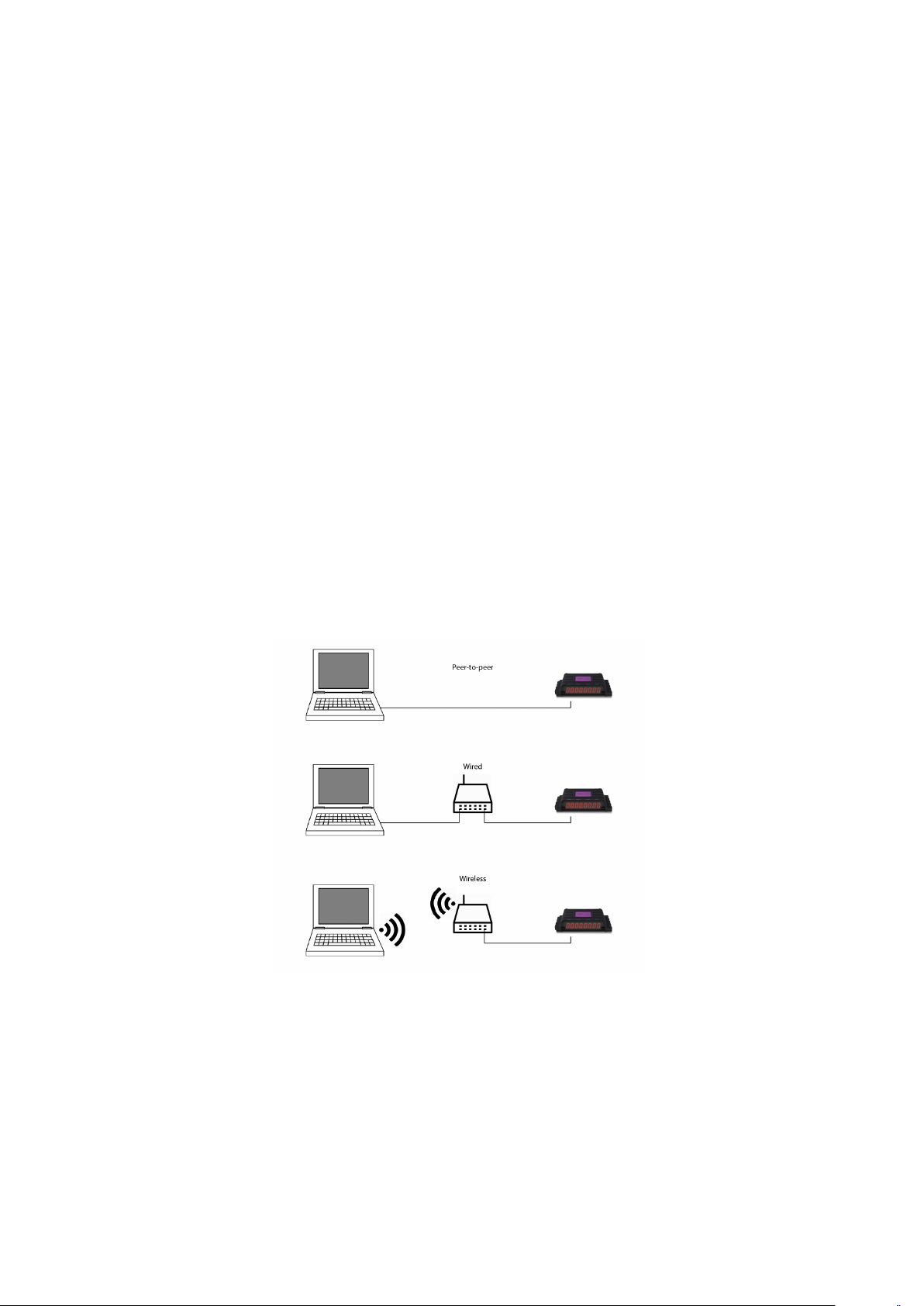
There are multiple arrangements possible for connecting the computer and the
TimeCore. They can be connected peer-to-peer, via a network switch or via
Wi-Fi. Figure 5.1 illustrates these different arrangements.
Figure 5.1: Network arrangements
The Ethernet port on the TimeCore is auto-sensing; it does not matter whether
a cross or straight network-cable is being used.
18

5.1 IP Address
The TimeCore supports both static IP addresses and automatic IP addresses.
By default, the TimeCore is set DHCP in which it will be automatically assigned an IP address by the DHCP server in the network. The ’DHCP server’
is typically part of the router’s functionality.
Static IP addresses are useful when there is no DHCP server in the network, for
instance when there is a direct peer-to-peer connection between a TimeCore and
a computer. It is also useful in permanent installations where the IP address
of the TimeCore is known by other equipment and therefor should not change.
When using DHCP there is always the risk of automatically being given a new
IP address in the event that the DHCP server is replaced. When using static IP
addresses make sure that all equipment on the network have unique IP addresses.
The TimeCore’s LED helps to determine which kind of IP address is set. The
LED will indicate red when using DHCP and it will indicate white in the case
of a static IP address.
There are three ways to change the IP address setting of the TimeCore.
• vManager can be used to detect a TimeCore on the network. Once
found, the vManager software (figure chapter 6) allows for changing the
IP address, subnet mask and DHCP settings.
• If the IP address is already known then browsing to this address using the
computer’s browser will show the TimeCore’s web-interface. The Set-
tings page on this web-interface enables changing the IP address, subnet
mask and DHCP settings.
• By briefly pressing the reset button on the device it toggles between
static and automatic IP addresses. By pressing and holding the reset
button (see figure 5.2) on the device for 3 seconds, it will reconfigure the
unit to the factory default IP address and subnet mask. No other settings
will be changed. The default IP address is 192.168.1.10 with the subnet
mask set to 255.255.255.0.
5.2 Access via Internet
The TimeCore can be accessed through the Internet. There are two ways to
achieve this: Port-Forwarding and VPN.
• Port-Forwarding Is relatively easy to setup in the router. Each router
is different so it is advised to consult the router’s documentation (sometimes it is revered to as NAT or Port-Redirecting). Please note that port
forwarding is not secure, since anybody could access the TimeCore this
way.
• Accessing via a Virtual Private Network (VPN) tunnel requires more
setup efforts, also the router needs to support the VPN feature. Once set
19

Figure 5.2: Reset button
up, this is a very secure way to communicate with the TimeCore. A VPN
is a network technology that creates a secure network connection over a
public network such as the Internet or a private network owned by a service
provider. Large corporations, educational institutions, and government
agencies use VPN technology to enable remote users to securely connect
to a private network. For further information about VPN please refer to
http://whatismyipaddress.com/vpn.
20

Chapter 6
vManager
A free-of-charge software tool called vManager has been developed to manage
the devices. This tool is available on Microsoft Windows, MacOS and Ubuntu
Linux via the Visual Productions website. vManager allows for:
• Setup the IP address, subnet mask, router and DHCP
• Backup and restore the device’s internal data and settings
• Perform firmware updates
• Set the real-time clock of the TimeCore (The computer’s date and time
will be used)
• Identify a specific device (in a multi device set-up) by blinking its LED
• Revert to factory defaults
The following section explain the buttons in the vManger, as seen in figure 6.1.
6.1 Backup
Backups of all the programming data inside the device can be made. This
backup file (an XML) is saved on the computer’s hard-disk and can be easily
transferred via e-mail or USB stick. The data of the backup can be restored via
the Restore button.
The backup files created by vManager can be found at the following loca-
tions:
Microsoft Windows \Users\[username]\Documents\Visual Productions\Common\Backups
MacOS /Users/[username]/Visual Productions/Common/Backups
Ubuntu Linux /home/[username]/Visual Productions/Common/Backups
21

Figure 6.1: vManager
Figure 6.2: Creating a backup
6.2 Upgrade Firmware
To upgrade the firmware, first select the device and press the Upgrade Firmware
button. The dialogue allows for selecting from the list of firmware versions
available.
Figure 6.3: Firmware upgrade
22

Warning: Make sure the power to the device is not interrupted during the
upgrade process.
6.3 Set Date & Time
The computer’s date and time can be quickly copied to the TimeCore by selecting a device and clicking the Set Date & Time button. Not all Visual
Productions devices feature an internal clock.
6.4 Blink
The device’s LED can be set to blink fast for identifying the particular unit
amongst multiple devices. The blinking is enabled by double-clicking on a device
in the Devices list or by selecting a device and then clicking the Blink button.
6.5 Factory Defaults
All the user data like cues, tracks and actions are stored on the memory. They
will be completely erased and all settings will reverted to their defaults by
pressing the Factory Defaults button. This action does not affect the device’s
IP settings.
23

Chapter 7
Show Control
The TimeCore can interact with the outside world; it can receive messages and
values through various protocols and it can send out many protocols. It is possible to automate the TimeCore by having it respond automatically to incoming
signals. An example of this would be to start the timecode upon receiving a
specific UDP network message. The Show Control page (See figure 7.1) enables
this kind of programming to be made.
Figure 7.1: Show Control page
The Show Control page presents a system of ’actions’. A signal that the
TimeCore needs to respond to or perhaps convert into some other signal, needs
to be expressed in an actions. With the exception of converting timecode protocols; this can be done in the Settings page (see page 30). Before programming
actions please consider the Show Control structure in figure 7.2.
24

Figure 7.2: Show Control structure
The TimeCore is capable of listening to various protocols. These available
protocols are listed in Sources, however, the TimeCore can only actively listen
to 8 protocols at once. The active protocols are listed in ’Action Lists’. Each
action list can contain actions. Within a protocol/source each individual signal
requires its own action. For example, when listening to channel 1 and 2 on
the incoming Art-Net, the Art-Net actionlist needs two actions; one for each
channel.
Inside the action we define the trigger and tasks. The trigger specifies for which
signal to filter. In the above Art-Net example the trigger would be set to ’channel 1’ and ’channel 2’ respectively. The tasks determine what the TimeCore
will do when this action is triggered. Several tasks can be placed in the action.
There are tasks available for a wide range of TimeCore features and external
protocols. Task types are detailed in Appendix C on page 46.
Please consult the API appendix on page 52 before implementing incoming
OSC or UDP messages; the API already exposes typical functionality through
OSC and UDP and therefor it might not be necessary to implement custom
messages.
7.1 Sources and Actionlists
The Sources listing presents all protocols that the TimeCore is capable of receiving. It also includes internal features that can create events that can be
used for triggering actions, such as the Randomizer. These sources are available, however, they will only be actively listened to once moved to the actionlist
table.
25

Buttons One of the two buttons is pressed
MIDI MIDI messages
UDP UDP network messages
TCP TCP network messages
OSC OSC network message
DMX Input DMX received on one or more of the DMX ports (switch
port to input in the settings page)
Art-Net Art-Net DMX data
sACN sACN DMX data
Timecode Timecode signal, specify the incoming timecode protocol on
the Settings page.
Touch Screen Triggers from VisualTouch. For each Action various
controls can be chosen such as buttons and sliders, colour
picker etc. The order of the actions will control the
arrangement in VisualTouch.
Randomiser The randomiser can generate a random number
System Events such as ’Power on’
Variable The Variable source works in combination with the variable
task (For more information about the Variable task please
refer to Task Types). The Variable task will set a value of
which an enabled actionlist type with Variable as Source
will use as a trigger. The TimeCore will keep the values of
the 8 variables even after shut down so long as the RTC
battery is not empty.
Timer There are 4 internal timers in the TimeCore. An event will
be raised when a timer expires. Timers are set and
activated by the Timer tasks.
Actionlist Events such as ’Power on’
User List 1-4 These actionlists will never trigger an event, however, they
are useful for advanced programming.
actionlists can be temporarily suspended by disabling their checkbox in the
Show Control page. There is also a task available to automate changing the
state of this checkbox.
7.2 Actions
Actions are executed when a certain signal is received. This signal is defined by
the trigger. A trigger is always relative to the actionlist the action belongs to.
For example, when the trigger-type is set to ’Channel’ then it refers to a single
sACN channel if the action is placed inside a ’sACN’ actionlist and it means a
single Art-Net channel if the action resides in an Art-Net actionlist.
26

A trigger is determined by the trigger-type, trigger-value and trigger-flank fields.
Although these fields are not applicable for all actionlists and are therefor sometimes omitted in the web GUI. The trigger-type field specifies what kind of signal
the action will be triggered by. For example, when making an action in the Button list there is the choice between ’Short press’ and ’Long press’ trigger-types.
In some actionlists actions do also need to specify the trigger-flank. The flank
further specifies the value that the signal should have before triggering the action. For example, when an action is triggered from a Touch Screen list and
it is linked to a button in the VisualTouch software, the flank will determine
whether to trigger only when the button goes down or only when it goes up.
Appendix B provides an overview of the available trigger-types.
An actionlist can have up to 48 actions, system-wide there is a maximum of
64 actions.
7.3 Tasks
Tasks are added to an action in order to specify what to do when it gets executed. Up to 8 tasks can be included in an action, systemwide there is a
maximum of 128 tasks. The tasks are executed in the order of the list. There
is a wide selection of tasks available to choose from, they include altering any
of the internal software features like playbacks and recorder but also sending
out messages through any of the supported protocols. The tasks are organised
in categories. Once a task is chosen from these categories each task allows for
further choice between several ’Features’ and ’Functions’. Tasks contain up to
two parameters that might be required for its execution.
A task can be tested by selecting it and pressing the ’execute’ button in the
action-edit dialog. The complete action can also be tested; go to the Show Control page, select the action and press the ’execute’ button.
Appendix A provides a detailed overview of the available tasks, features, functions and parameters.
7.4 Templates
The Show Control page presents a list of templates. A template is a set of actionlists, actions and task. These templates configure the TimeCore to perform
typical functions; for example convert start and stop the internal timecode by
pressing the front push-buttons. The templates thus save time; otherwise actions should have been set up manually. They can also function as a guide to
soften the learning curve on actions; a lot can be learned from adding a template and then exploring the actions and tasks it created. Please note that some
templates require settings to changed in the settings page.
27

Chapter 8
Monitors
This page allows the user to inspect the incoming and outgoing data, both
DMX-type data (See figure 8.1) as well as control messages (See figure 8.2).
Monitoring incoming and outgoing data can help the user troubleshoot during
programming.
28

Figure 8.1: Art-Net Monitor page
Figure 8.2: OSC Monitor page
29
Chapter 9
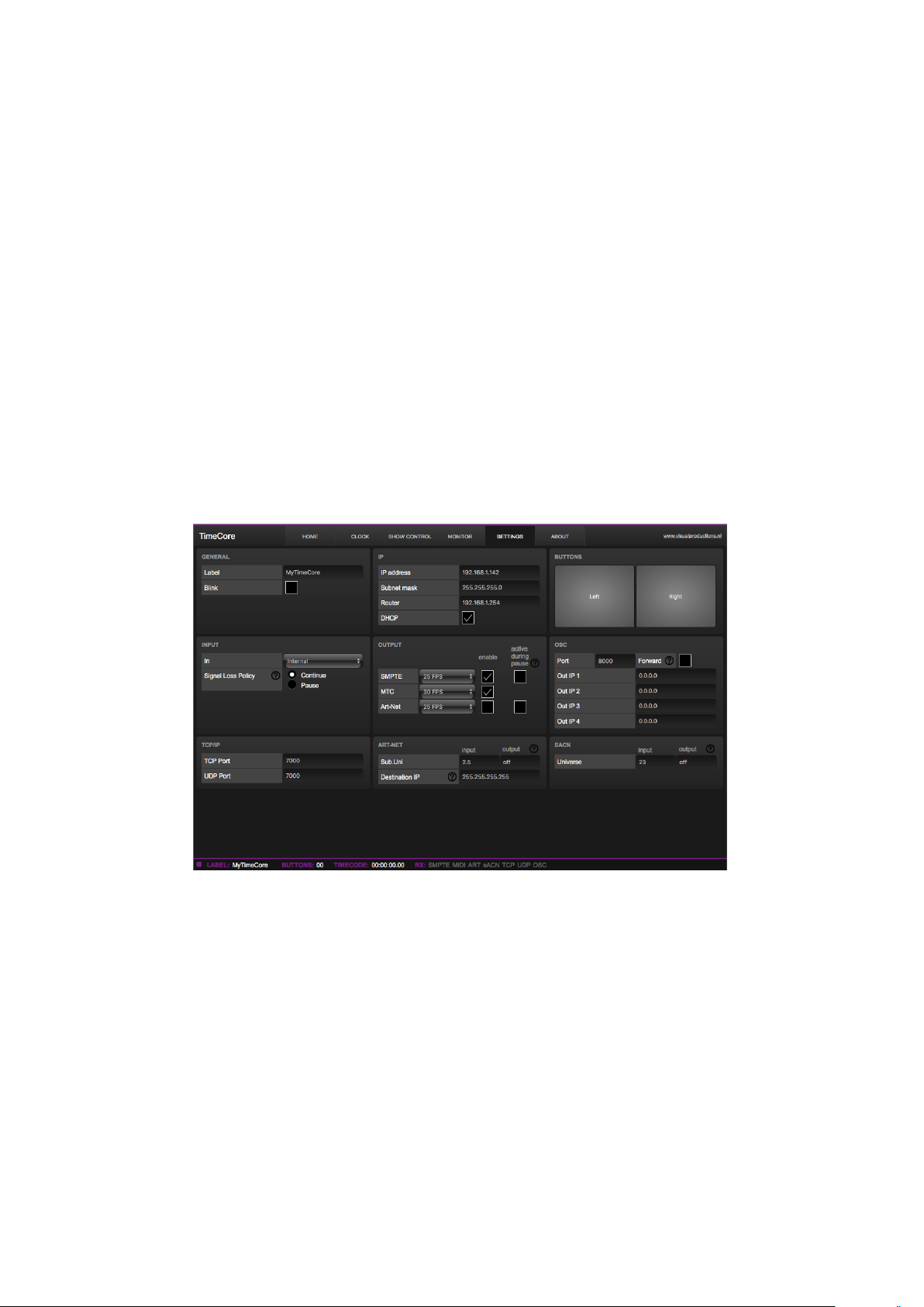
Settings
The TimeCore’s settings are organised into sections, see the Settings page figure
9.1. This chapter will discuss each section.
Figure 9.1: Settings page
9.1 General
You can change the TimeCore’s label. This label can be used to distinguish the
unit in a set-up with multiple devices. By enabling the ’Blink’ checkbox the
device’s LED will blink to help to identify it amongst multiple devices.
30

Figure 9.2: General Settings
9.2 IP
The IP fields are for setting up the IP address and subnet mask of the TimeCore.
The ’Router’ field is only required when Port Forwarding is used. You can also
enable or disable the DHCP feature (For more information see chapter 5 at page
18).
Figure 9.3: IP Settings
9.3 Buttons
The two buttons in the web-interface mimic the two push-buttons on the physical device. These software buttons are useful for testing or controlling the unit
when it is placed out of your reach.
31

Figure 9.4: Buttons Settings
9.4 Input
This section determines the timecode source for the TimeCore. The options are:
Source Description
Internal Timecode will be generated internally by the TimeCore
SMPTE LTC signal received on SMPTE IN connector
MTC MTC signal received on MIDI IN connector
Art-Net Art-Net timecode received via the network port
Figure 9.5: Input settings
The SMPTE and Art-Net protocol do not offer means to distinguish a signal
loss from a ’pause’ of the time. Therefor, the ’Signal Loss Policy’ allows you to
control how an interruption in the timecode signal should be interpreted.
32

Policy Description
Continue In the case of a signal loss the TimeCore will continue the
timecode by using its internal clock. When the signal reappears
the TimeCore will sync again to it.
Pause The TimeCore will pause the timecode when the signal is lost.
It will continue the timing as soon as the signal is restored.
9.5 Output
This section controls if any timecode protocol is transmitted from the TimeCore.
Each timecode protocol has its own frame-rate setting.
Figure 9.6: Output settings
The SMPTE and Art-Net protocol do not offer means to indicate a ’pause’ of
the timecode signal. Therefor, the TimeCore offers an ’active during pause’
checkbox to control the behaviour of the SMPTE and Art-Net signal during a
pause state.
When disabled, both SMPTE and Art-Net signal will cease; no signal will
be generated. In this case it is hard for the recipient to determine the difference
between a ’pause’ and ’signal loss’.
When ’active during pause’ is enabled for SMPTE then the TimeCore will
generate invalid SMPTE frames during the pause. This enabled the recipient
to still detect activity on the SMPTE line (this would not be the case during a
signal loss). When the checkbox is enabled for Art-Net then the TimeCore will
continue repeating the last timecode frame during the pause.
9.6 OSC
External equipment sending OSC messages to the TimeCore need to be aware
of the number specified in the ’Port’ field. This is the port the TimeCore listens
to for incoming messages.
The TimeCore will send its outgoing OSC messages to the IP addresses specified in the ’Out IP’ fields. Up to four IPs can be specified here. Use the ’ipaddress:port’ format in these fields, e.g. ”192.168.1.11:9000”. If a field should not
33

Figure 9.7: OSC Settings
be used that it can be filled with IP 0.0.0.0:0. It is possible to enter a broadcast
IP address like 192.168.1.255 in order to reach more than four recipients.
Enabling the ’Forward’ checkbox will have the TimeCore copy every incoming
OSC message and send it the addresses specified in the ’Out IP’ fields.
9.7 TCP/IP
Defines the listening ports for TCP and UDP messages. External system intending to send TCP or UDP message to the TimeCore should need to know
the unit’s IP address and this port number. By default both ports are set to
7000.
Figure 9.8: TCP/IP settings
9.8 Art-Net
The Art-Net (DMX data) feature in the TimeCore supports one universe out and
one universe in. These universes can be mapped to any of the 256 available universes in the Art-Net protocol. The universe is entered in the ’subnet.universe’
format, i.e. the lowest universe number is written as ’0.0’ and the highest universe number is denoted as ’15.15’. The outgoing Art-Net transmission can be
disabled by entering ’off’ in the output field.
The destination IP determines where the outgoing Art-Net data will be
send to. Typically, this field contains a broadcast address like 2.255.255.255
which will send the Art-Net data to the 2.x.x.x IP range. Another typical
34

Figure 9.9: Art-Net settings
Art-Net broadcast address is 10.255.255.255. When using broadcast address
255.255.255.255 then all the devices on the network will receive the Art-Net
data.
It is also possible to fill in a unicast address like 192.168.1.11; in this case
the Art-Net data will be send to one IP address only. This keeps the rest of the
network clean of any Art-Net network messages.
9.9 sACN
Figure 9.10: sACN settings
The TimeCore supports one incoming sACN universe and one outgoing universe. Each universe field should hold a number in the range of [1,63999].
Outgoing sACN transmission can be disabled by entering ’off’ into the sACN
output field.
35

Appendices
36

Appendix A
Templates
This appendix discusses the templates provided in the Show Control page.
Template Description
Buttons ->Timecode Configures the left push-button as a Start/Pause-command and the
right push-button as a Restart-command.
37

Appendix B
Trigger Types
The following tables list the different types of triggers that can be used in the
TimeCore. The different types are accompanied with values and flanks.
B.1 Button
Trigger Type Trigger Value Flank Description
Button Button number Change Button state changes
Button Button number Down Button is depressed
Button Button number Up Button is released
Short press Button number - Button is depressed momentary
Long press Button number - Button is depressed for long time
B.2 MIDI
Trigger Type Trigger Value Flank Description
MIDI Address Address Change Receive a message that matches the address
MIDI Address Address Down Receive a message that matches the address and
the value non-zero
MIDI Address Address Up Receive a message that matches the address and
the value is zero
Receiving - - Receive any message
MIDI address can be any note-on, note-off, control-change, program-change
and machine-control.
38

B.3 UDP
Trigger Type Trigger Value Flank Description
Message String - Receive a message that matches the trigger-value
Receiving - - Receive any message
The user can define his own string as the trigger value of a message. Please
note that this string has a maximum length of 31 characters.
B.4 TCP
Trigger Type Trigger Value Flank Description
Message String - Receive a message that matches the trigger-value
Receiving - - Receive any message
The user can define his own string as the trigger value of a message. Please
note that this string has a maximum length of 31 characters.
B.5 OSC
Trigger Type Trigger Value Flank Description
Message URI Change Receive a message that matches the URI
Message URI Down Receive a message that matches the URI and the
value non-zero
Message URI Up Receive a message that matches the URI and the
value is zero
Receiving - - Receive any message
The user can define his own URI as the trigger value of a message, however,
the OSC specification dictate this string must start with a ’/’ sign. Please note
that this string has a maximum length of 31 characters, including the ’/’.
39

B.6 Art-Net
Channel DMX Address Change Channel changes
Channel DMX Address Non-zero Channel becomes non-zero
Channel DMX Address Zero Channel becomes zero
UniverseA - - A DMX level change in the first universe
Receiving - Change Start receiving or loose Art-Net signal
Receiving - Stop Lost Art-Net signal
Receiving - Start Start receiving Art-Net signal
B.7 sACN
Trigger Type Trigger Value Flank Description
Channel DMX Address Change Channel changes
Channel DMX Address Non-zero Channel becomes non-zero
Channel DMX Address Zero Channel becomes zero
UniverseA - - A DMX level change in the first universe
Receiving - Change Start receiving or loose sACN signal
Receiving - Stop Lost sACN signal
Receiving - Start Start receiving sACN signal
40

B.8 Timecode
Trigger Type Trigger Value Flank Description
Time Frame - Timecode frame
Playing - - Timecode started
Paused - - Timecode paused
Stopped - - Timecode stopped
Receiving SMPTE - Change Start receiving or loose timecode signal
Receiving SMPTE - Stop Lost timecode signal
Receiving SMPTE - Start Start receiving timecode signal
Receiving MTC - Change Start receiving or loose timecode signal
Receiving MTC - Stop Lost timecode signal
Receiving MTC - Start Start receiving timecode signal
Receiving Art-Net - Change Start receiving or loose timecode signal
Receiving Art-Net - Stop Lost timecode signal
Receiving Art-Net - Start Start receiving timecode signal
B.9 Touch Screen
Trigger Type Trigger Value Flank Description
- - Change Button/Fader goes up or down
- - Down Button is pressed
- - Up Button is released
B.10 Randomizer
Trigger Type Trigger Value Flank Description
Result - - The Randomizer made a new
value
Specific Value Number in the range of [0,255] - The Randomizer made a value
that matches
41

B.11 System
Trigger Type Trigger Value Flank Description
Startup - - The TimeCore has been power up
Network Connection - Change Network connection established or lost
Network Connection - Stop Network connection lost
Network Connection - Start Network connection established
ReleasedByMaster - Change Master (e.g. CueluxPro) released or
obtained connection
ReleasedByMaster - Stop Master released connection
ReleasedByMaster - Start Master obtained connection
42

43

B.12 Variable
Trigger Type Trigger Value Flank Description
Channel Variable Index - The specified variable changes
Variable 1 Number in the
range of [0,255]
Variable 1 Number in the
range of [0,255]
Variable 1 Number in the
range of [0,255]
Variable 2 Number in the
range of [0,255]
Variable 2 Number in the
range of [0,255]
Variable 2 Number in the
range of [0,255]
Variable 3 Number in the
range of [0,255]
Variable 3 Number in the
range of [0,255]
Variable 3 Number in the
range of [0,255]
Variable 4 Number in the
range of [0,255]
Change Variable 1 becomes equal or not equal to
the specified number
Equal Variable 1 becomes equal to the specified
number
Unequal Variable 1 becomes not equal to the
specified number
Change Variable 2 becomes equal or not equal to
the specified number
Equal Variable 2 becomes equal to the specified
number
Unequal Variable 2 becomes not equal to the
specified number
Change Variable 3 becomes equal or not equal to
the specified number
Equal Variable 3 becomes equal to the specified
number
Unequal Variable 3 becomes not equal to the
specified number
Change Variable 4 becomes equal or not equal to
the specified number
Variable 4 Number in the
range of [0,255]
Variable 4 Number in the
range of [0,255]
Variable 5 Number in the
range of [0,255]
Variable 5 Number in the
range of [0,255]
Variable 5 Number in the
range of [0,255]
Variable 6 Number in the
range of [0,255]
Variable 6 Number in the
range of [0,255]
Variable 6 Number in the
range of [0,255]
Variable 7 Number in the
range of [0,255]
Variable 7 Number in the
range of [0,255]
Equal Variable 4 becomes equal to the specified
number
Unequal Variable 4 becomes not equal to the
specified number
Change Variable 5 becomes equal or not equal to
the specified number
Equal Variable 5 becomes equal to the specified
number
Unequal Variable 5 becomes not equal to the
specified number
Change Variable 6 becomes equal or not equal to
the specified number
Equal Variable 6 becomes equal to the specified
number
Unequal Variable 6 becomes not equal to the
specified number
Change Variable 7 becomes equal or not equal to
44
Equal Variable 7 becomes equal to the specified
the specified number
number
Variable 7 Number in the
range of [0,255]
Variable 8 Number in the
Unequal Variable 7 becomes not equal to the
specified number
Change Variable 8 becomes equal or not equal to

B.13 Timer
Trigger Type Trigger Value Flank Description
- Timer # Change The timer starts or stops
- Timer # Stop The timer stops
- Timer # Start The timer starts
B.14 Actionlist
Trigger Type Trigger Value Flank Description
- Actionlist # Change Enabled checkbox changed
- Actionlist # Down Enabled checkbox set
- Actionlist # Up Enabled checkbox cleared
45

Appendix C
Task Types
Actionlist Tasks allow you to automate the functionality in the TimeCore. All
this functionality is categorized in task-types. This appendix provides a listing
of the various task-types. The tables present an overview of all available features
and functions per task-type.
C.1 Action
Trigger another action.
Feature Function Parameter 1 Parameter 2
Link Set Action -
C.2 Actionlist
Manipulate an actionlist.
Feature Function Parameter 1 Parameter 2
Enable Set Actionlist On or Off
Enable Toggle Actionlist -
Enable Control Actionlist -
Enable Inverted Control Actionlist -
C.3 Button
Force the GPI actions to be triggered.
Feature Function Parameter 1 Parameter 2
Refresh Set - -
46

C.4 DMX
Manipulate the DMX levels. These levels can be send out via Art-Net or sACN.
Feature Function Parameter 1 Parameter 2
Universe Control HTP Universe # -
Universe Control LTP Universe # -
Universe Control Priority Universe # -
Universe Clear Universe # -
Channel Set DMX Channel DMX Value
Channel Toggle DMX Channel -
Channel Control DMX Channel -
Channel Inverted Control DMX Channel -
Channel Decrement DMX Channel -
Channel Increment DMX Channel -
Bump Set DMX Channel DMX Value
Bump Control DMX Channel -
Clear Set - -
RGB Set DMX Address RGB Colour Value
RGB Control DMX Address -
RGBA Control DMX Address -
XY Control DMX Address -
XxYy Control DMX Address -
C.5 MIDI
Send an MIDI message.
Feature Function Parameter 1 Parameter 2
Send Set MIDI Address MIDI Value
Send Control MIDI Address -
C.6 MMC
Send an MMC (MIDI Machine Control) message via the MIDI port.
47

Feature Function Parameter 1 Parameter 2
Send Start MIDI Channel -
Send Stop MIDI Channel -
Send Restart MIDI Channel -
Send Pause MIDI Channel -
Send Record MIDI Channel -
Send Deferred Play MIDI Channel -
Send Record Exit MIDI Channel -
Send Record Pause MIDI Channel -
Send Eject MIDI Channel -
Send Chase MIDI Channel -
Send Fast Forward MIDI Channel -
Send Rewind MIDI Channel -
Send Goto MIDI Channel Time
C.7 MSC
Send an MSC (MIDI Show Control) message via the MIDI port.
Feature Function Parameter 1 Parameter 2
Send Set Control Number [0,16383] Control Value [0,16383]
Send Start Q number Q list
Send Stop Q number Q list
Send Resume Q number Q list
Send Load Q number Q list
Send Fire Macro -
Send All Off - -
Send Restore - -
Send Reset - -
Send Go Off Q number Q list
C.8 OSC
Send an OSC message via the network. The OSC recipients are specified in the
Settings page.
48

Feature Function Parameter 1 Parameter 2
Send Float Set URI floating point number
Send Float Control URI -
Send Unsigned Set URI positive number
Send Unsigned Control URI -
Send Bool Set URI true or false
Send Bool Control URI -
Send String Set URI String of characters
Send String Control URI -
Colour Set URI RGB colour
Colour Control URI -
Please note that string in parameter 1 has a maximum length of 31 characters, including the compulsory leading ’/’ sign.
C.9 UDP
Send an UDP message via the network. Specify the recipient in Parameter 2.
For example ”192.168.1.11:7000”.
Feature Function Parameter 1 Parameter 2
Send Float Set floating point number IP address & port
Send Float Control - IP address & port
Send Unsigned Set positive number IP address & port
Send Unsigned Control - IP address & port
Send Bool Set true or false IP address & port
Send Bool Control - IP address & port
Send String Set text string IP address & port
Send String Control - IP address & port
Please note that string in parameter 1 has a maximum length of 31 characters.
C.10 Randomiser
Trigger the Randomizer to generate a new random number.
Feature Function Parameter 1 Parameter 2
Refresh Set Minimum value Maximum value
49

C.11 System
Miscellaneous tasks.
Feature Function Parameter 1 Parameter 2
Blink Set On or Off -
Blink Toggle - -
Blink Control - -
Display Set Duration Text
Display Control Duration -
C.12 Timecode
Manipulate the internal timecode generator.
Feature Function Parameter 1 Parameter 2
Playstate Start - -
Playstate Stop - -
Playstate Restart - -
Playstate Pause - -
Playstate Toggle Start Pause - -
Playstate Toggle Start Stop - -
Time Set - Timecode frame
Source Set Source -
Source Toggle Source Source
Source Increment - -
Autonoom Pause Set On/Off -
Enable Set Source On/Off
C.13 Timer
Manipulate on of the four internal timers.
50

Feature Function Parameter 1 Parameter 2
Playstate Start Timer # -
Playstate Stop Timer # -
Playstate Restart Timer # -
Time Set Timer # Time
C.14 Variable
Manipulate one of the eight variables.
Feature Function Parameter 1 Parameter 2
Set Value Set Variable # Number in the range of [0,255]
Set Value Toggle Variable # Number in the range of [0,255]
Set Value Control Variable # -
Set Value Inverted Control Variable # -
Set Value Decrement Variable # -
Set Value Increment Variable # -
Set Value Control Scaled Variable # -
Set Value Control Offset Variable # -
Refresh Set Variable # -
Single Dimmer Set Variable # Delta
51

Appendix D
API
The TimeCore is pre-programmed to make its internal functionality available via
OSC and UDP. There is a simple API implemented for each protocol. Notwithstanding these API’s, it is possible to create your own OSC and UDP implementation in the Show Control page.
D.1 OSC
The following table uses actionlist #1 as an example. The number ’1’ can be
replaced by any number in the range of [1,8]. The table also uses action #2 as
an example. The number ’1’ can be replaced by any number in the range of
[1,48].
URI Parameter Description
/core/al/1/2/execute bool/float/integer Execute action #2 inside action list #1
/core/al/1/enable bool Set the ’enable’ checkbox for action list #1
The following table shows how to manipulate the internal timecode.
URI Parameter Description
/core/tc/start - Start timecode
/core/tc/stop - Stop timecode
/core/tc/restart - Restart timecode
/core/tc/pause - Pause timecode
/core/tc/set time-string Set the timecode frame at the specified string. For example
”23:59:59.24”
The following table uses timer #1 as an example. The number ’1’ can be
replaced by any number in the range of [1,4].
52

URI Parameter Description
/core/tm/1/start - Start timer #1
/core/tm/1/stop - Stop timer #1
/core/tm/1/restart - Restart timer #1
/core/tm/1/pause - Pause timer #1
/core/tm/1/set time-string Set timer #1 at the time-string
The following table uses variable #1 as an example. The number ’1’ can be
replaced by any number in the range of [1,8].
URI Parameter Description
/core/va/1/set integer Set the value of variable #1
/core/va/1/refresh - Refresh variable #1; a trigger will be generated as if the
variable changed value
/core/va/refresh - Refresh all variables; triggers will be generated
The following table shows how to active miscellaneous functions.
URI Parameter Description
/core/blink - Momentarily flashes the TimeCore’s LED
D.2 UDP
The following table uses actionlist #1 as an example. The number ’1’ can be
replaced by any number in the range of [1,8]. The table also uses action #2 as
an example. The number ’1’ can be replaced by any number in the range of
[1,48].
String Description
core-al-1-1-execute=<arg> Execute action #2 inside action list #1
core-al-1-enable=<bool> Set the ’enable’ checkbox for action list #1
The following table shows how to manipulate the internal timecode.
String Description
core-tc-start Start timecode
core-tc-stop Stop timecode
core-tc-restart Restart timecode
core-tc-pause Pause timecode
core-tc-set=<text> Set the timecode frame at the specified string. For example
”23:59:59.24”
53

The following table uses timer #1 as an example. The number ’1’ can be
replaced by any number in the range of [1,4].
String Description
core-tm-1-start Start timer #1
core-tm-1-stop Stop timer #1
core-tm-1-restart Restart timer #1
core-tm-1-pause Pause timer #1
core-tm-1-set=<text> Set timer #1 at the time-string
The following table uses variable #1 as an example. The number ’1’ can be
replaced by any number in the range of [1,8].
String Description
core-va-1-set=<integer> Set the value of variable #1
core-va-1-refresh Refresh variable #1; a trigger will be generated as if the
variable changed value
core-va-refresh Refresh all variables; triggers will be generated
The following table shows how to active miscellaneous functions.
String Description
core-blink Momentarily flashes the TimeCore’s LED
54

Index
Action, 24
Action list, 25
Active during pause, 33
API, 52
Art-Net, 9, 34
Auto-sensing, 18
Backup, 21
Blink, 23
Box contents, 6
Buttons, 31
Date, 23
Destination IP, 34
DHCP, 10, 19
Factory Defaults, 23
Feature, 46
Firmware, 22
Flank, 27, 38
Function, 46
General, 30
Input, 32
Internal, 32
IP, 31
Kensington, 16
Pause, 33
PoE, 17
Port-Forwarding, 19
Quickstart, 11
Reset button, 19
sACN, 9, 35
Settings, 30
Show Control, 24
Signal Loss Policy, 32
SMPTE, 8
Source, 25
Subnet mask, 19
Task, 25
Task type, 46
TCP, 9, 34
TCP/IP, 34
Template, 27
Templates, 37
Time, 23
Trigger, 25
Trigger type, 38
Tutorial, 11
UDP, 10, 34
URI, 39
LED, 19
LTC, 8
Memory, 7
MIDI, 8, 38
MMC, 8, 47
Monitor, 28
MSC, 9, 48
MTC, 8
OSC, 10, 33
Output, 33
vManager, 21
VPN, 19
55
 Loading...