


CUECORE3
MANUAL
© VISUAL PRODUCTIONS BV WWW.VISUALPRODUCTIONS.NL

Revision History
Revision Date Author(s) Description
1 29.03.2021 ME Initial version.
1 20.06.2022 ME Added Patch and Purple Cloud.
2

Contents
1 Introduction 7
2 Protocols 13
3 Quickstart 19
4 Installation 33
5 Network 36
6 Operating Modes 40
7 Patch 44
8 Tracks 47
9 Playbacks 54
10 Show Control 61
11 Protocol Conversion 74
12 Monitors 79
13 Settings 82
14 Purple Cloud 92
15 vManager 95
16 Kiosc 100
Appendices 102
A Trigger Types 103
B Task Types 114
C Templates 127
3

D API 128
4

c
2022 Visual Productions BV. All rights reserved.
No parts of this work may be reproduced in any form or by any means - graphic,
electronic, or mechanical, including photocopying, recording, taping, or information storage and retrieval systems - without the written permission of the
publisher.
While every precaution has been taken in the preparation of this document, the
publisher and the author assume no responsibility for errors or omissions, or for
damages resulting from the use of information contained in this document or
from the use of programs and source code that may accompany it. In no event
shall the publisher and the author be liable for any loss of profit or any other
commercial damage caused or alleged to have been caused directly or indirectly
by this document.
Due to the dynamic nature of product design, the information contained in this
document is subject to change without notice. Revisions of this information or
new editions may be issued to incorporate such changes.
Products that are referred to in this document may be either trademarks and/or
registered trademarks of the respective owners. The publisher and the author
make no claim to these trademarks.
5

EU Declaration of Conformity
We, manufacturer Visual Productions BV, herby declare under sole responsibility,
that the following device:
CueCore3
Conforms to the following EC Directives, including all amendments:
EMC Directive 2014/30/EU
And the following harmonized standards have been applied:
NEN-EN-IEC 61000-6-1:2007
NEN-EN-IEC 61000-6-3:2007
The object of the declaration is in conformity with the relevant Union
harmonisation Legislation.
Full name and identication of the person responsible for product quality and
accordance with standards on behalf of the manufacturer
Date: Place:
March 29th, 2021 Haarlem, The Netherlands
ing. Maarten Engels
Managing Director
Visual Productions BV
VISUAL PRODUCTIONS BV
IZAAK ENSCHEDEWEG 38A
NL-2031CR HAARLEM
THE NETHERLANDS
TEL +31 (0)23 551 20 30
WWW.VISUALPRODUCTIONS.NL
INFO@VISUALPRODUCTIONS.NL
ABN-AMRO BANK 53.22.22.261
BIC ABNANL2A
IBAN NL18ABNA0532222261
VAT NL851328477B01
COC 54497795

Chapter 1
Introduction
Thank you for choosing the CueCore3; a lighting controller designed for (semi)permanent installations. The CueCore3 is the most powerful controller developed so far by the engineers at Visual Productions.
We hope you will create beautiful lighting installations using the CueCore3 and
enjoy commissioning your CueCore3 projects as much as we enjoyed designing
this new controller.
Figure 1.1: CueCore3
At the time of writing this manual the CueCore3’s firmware was at version
1.26.20.
1.1 Design Goals
The CueCore3 builds on the success of the CueCore2 and QuadCore, using the
same functionality, while at the same time expanding capacity and adding new
7

features. The CueCore3 will not make the CueCore2 obsolete, rather it will
give the user an additional choice for a lighting controller for more demanding
projects, offering even more capabilities than the CueCore2.
The key extensions offered by the CueCore3 are:
1.1.1 Track Capacity
Featuring a flash memory 256 times the size of the memory in a CueCore2,
the CueCore3 can store considerably longer DMX recordings. This makes the
CueCore3 the preferred choice for channel heavy LED pixel projects.
1.1.2 Number of Playbacks
The number of playbacks has been increased from 6 to 16. The additional
playbacks makes it easier to program multiple zones or create more interactivity
by having various external triggers activate different playbacks.
1.1.3 Number of Actions
The CueCore3’s larger memory also facilitates a higher number of actions and
tasks to be programmed in the show control section. Taking the automation of
the lighting controller to the next level.
1.1.4 RDM
The DMX ports are bi-directional and RDM capable, featuring RDM discovery
and remote addressing.
1.1.5 Four Universes
The CueCore3 is has four DMX ports fitted with 5-pin XLR connectors. Each
port has an independent optical isolation; a surge on one DMX port is preventing
from affecting the other ports.
1.1.6 Patch
The previous CueCores did not contain fixture information; they only have
DMX channel data. The new CueCore3, however, features a patch. In this
patch the user can - it is optional - enter the fixture data like starting address
and personality. When the patch is setup then the CueCore3 is capable of
controlling the fixture’s parameters. Also, the patch is used for determining the
intensity channels when smartly dimming playbacks containing pre-recorded
tracks. In the CueCore2 this function relied on the Intensity Map.
8

1.1.7 Purple Cloud
The CueCore3 is designed to be remotely monitored and controlled by the Purple Cloud. The Purple Cloud is cloud service that has been developed by Visual
Productions parallel to the development of the CueCore3.
1.2 Features
The feature set of the CueCore3 includes:
• 4x DMX-512 (ANSI E1.11) optically isolated port (bi-directional)
• RDM (ANSI E1.20)
• 4x GPI
• MIDI, MSC & MMC
• SMPTE, MTC & Art-Net timecode
• Art-Net, sACN & KiNet
• TCP, UDP & OSC
• Master-slave protocol for synchronising multiple CueCore3 units
• Scheduling with Real-Time clock1, weekdays and sunrise/sunset
• NTP time synchronisation
• Desktop or DIN Rail mounted
• Kensington lock
• Locked power cable protection
• PoE (Power Over Ethernet) Class I
• Bundled with CueluxPro, vManager and Kiosc software
1.3 Comparison
The following table visualises the difference between the CueCore3, CueCore2 ,
QuadCore and CueCore1. This overview might prove to be helpful to CueCore
users considering choosing the model for their new designs.
1
Please note that there is no battery fitted inside the CueCore3. The Real-Time clock has
a backup charge through means of a super-capacitor.
9

CueCore3 QuadCore CueCore2 CueCore1
CPU 4x1.2GHz 180MHz 180MHz 120MHz
Memory 8GB 32MB 32MB 8MB
DMX 4 in/out 4 in/out 2 in/out 2 out + 1 in
RDM yes - - -
MIDI in+out - in+out in+thru+out
GPI 4x digital/analog - 4x digital/analog 4x digital
SMPTE in - in in
MTC in+out - in+out in
Art-Net in+out in+out in+out in+out
sACN in+out in+out in+out -
KiNet out out out -
TCP in+out in in -
UDP in+out in+out in+out in+out
OSC in+out in+out in+out in+out
POE class I class I class I class I
DHCP yes yes yes -
NTP yes yes yes -
Real-time Clock yes yes yes yes
CueluxPro 4 universes 4 universes 2 universes 2 universes
1.4 Limitations
The CueCore3 is a powerful device with many possibilities, there are however
some limitations, as shown in the following table.
10

Playbacks 16
Cues per Playback 32
Tracks 128
Action lists Each source once
Actions per list 64
Actions system-wide 128
Tasks per Action 16
Tasks system-wide 256
Variables 20
Timers 4
1.5 What’s in the box?
The CueCore3 packaging contains the following items (see figure 1.2):
• CueCore3
• Ethernet cable
• 6-pin terminal
• Power supply
• 4x international plug
• Information card
Figure 1.2: CueCore3 box contents
11

1.6 Saving data to memory
This manual will describe how to configure the CueCore3 and program tracks,
playbacks, action, etc. The unit’s web-interface is used for editing these kinds
of elements. When changes are made, these changes are directly stored in the
RAM memory of the CueCore3 and the programming will directly influence the
behaviour of the unit. RAM memory is, however, volatile and its content will be
lost through a power cycle. For this reason the CueCore3 will copy any changes
in the RAM memory to its onboard flash memory. Flash memory retains its
data even when not powered. The CueCore3 will load all its data back from the
flash memory upon startup.
This memory copy process is conducted automatically by the CueCore3 and
should not be of any concern of the user. One point of consideration is, however,
that after making a change the unit should be given time to perform the copy to
flash. As a rule of thumb, do not disconnect the power from the device within
30 seconds from making a programming change.
1.7 Document Organisation
This manual discusses setting up and programming the unit. Chapter 2 provides
background information on the communication protocols used the CueCore3.
Chapters 4 and 5 cover how to set up the unit and configure the network connection.
The Patch information is needed when controlling fixtures directly. This page
is covered in Chapter 7.
Chapter 8 and 9 cover recording, storing and playback of lighting content.
Programming the automation, triggering and converting functionality is done
in chapter 10.
Supporting tools such as Purple Cloud, vManager and Kiosc are explained in
chapters 14, 15 and 16 respectively.
When in a hurry, you could skip all chapters and directly follow the quickstart
tutorials in chapter 3.
1.8 Further Help
If, after reading this manual, you have further questions then please consult
the online forum at http://forum.visualproductions.nl for more technical
support.
12

Chapter 2
Protocols
The CueCore3 is fitted with several communication ports and supports various
protocols. This chapter describes these protocols and to which extent they are
implemented in the CueCore3
2.1 DMX-512
DMX-512 is the standard communication protocol for stage lighting. Its official
name is E1.11-2008 USITT DMX512-A. Nowadays the reach of the DMX protocol has extended beyond entertainment lighting and is also used for architectural
lighting.
Originally one DMX network contained 512 channels which is called a ’universe’.
With the growing size and complexity of lighting systems it is now very common
for a system to compose of multiple universes, each conveying 512 channels.
It is advised to use a shielded twisted pair cable for DMX cabling. The cable
should be terminated with an 120 Ohm resistor.
DMX-512 is a very successful protocol with, however, a few limitations. The
maximum number of attached devices is limited to 32 and they all have to be
connected in bus-topology having one cable running via each device. Furthermore, a DMX-512 cable should not be longer than 300 meters.
13

Figure 2.1: Visual Productions’ RdmSplitter
The DIN Rail RdmSplitter from Visual Productions (See figure 2.1) helps tackle
those inconvenient limitations. The Splitter takes a DMX signal and sends it
out again on its 6 DMX output ports for scaling group topology. Each output
port is capable of driving 32 more devices. The Splitter can also function as a
signal booster as each port supports another 300 meter long connection.
2.2 RDM
The Remote Device Management (RDM) protocol - officially called ANSI E1.20
- is build on top of the DMX-512 protocol. RDM enhances DMX with bidirectional communication allowing the fixtures to be detected, addressed and
polled for status information.
Although standard DMX cables can be used, the equipment requires specific
electronic considerations for being RDM capable.
The CueCore3 can discover RDM fixtures, set starting addresses and choose
modes.
2.3 Art-Net
The Art-Net protocol primarily transfers DMX-512 data over Ethernet. The
high bandwidth of an Ethernet connection allows Art-Net to transfer up to 256
universes.
The data sent out for Art-Net does put a certain load on the network, therefore
it is recommended to disable Art-Net when not in use.
Additional to transmitting DMX-512 data, Art-Net can also be used for transferring timecode information for equipment synchronisation.
Each CueCore3 supports sending and receiving of 2 Art-Net universes as well
as receiving Art-Net timecode.
14

2.4 sACN
The streaming Architecture of Control Networks (sACN) protocol uses a method
of transporting DMX-512 information over TCP/IP networks. The protocol is
specified in the ANSI E1.31-2009 standard.
The sACN protocol supports multi-cast in order to take efficient use of the
network’s bandwidth.
The CueCore3 supports sending and receiving of 2 sACN universes.
2.5 KiNet
KiNet is a proprietary protocol of Philips Color Kinetics to control their LED
fixtures and power supplies. It is a lightweight Ethernet-based protocol that
carries DMX-style data. Within the CueCore3 it can only be used to output
data.
2.6 TCP
The Transmission Control Protocol (TCP) is a core protocol of the Internet
Protocol Suite. It is used for its reliable, ordered and error checked delivery
of a stream of bytes between applications and hosts over IP networks. It is
considered ’reliable’ because the protocol itself checks to see if everything that
was transmitted was delivered at the receiving end. TCP allows for the retransmission of lost packets, thereby making sure that all data transmitted is
received.
The CueCore3 supports receiving and sending TCP messages.
2.7 UDP
User Datagram Protocol (UDP) is a simple protocol for sending messages across
the network. It is supported by various media devices like video projectors and
Show Controllers. It does not incorporate error checking, therefor it is faster
than TCP but less reliable.
There are two ways how to have the CueCore3 respond to incoming UDP messages. The API (see page 131) makes typical CueCore3 functions available
through UDP. Furthermore, custom messages can be programmed in the Show
Control page (see page 61). This is also the place where to program outgoing
UDP messages.
15

2.8 OSC
Open Sound Control (OSC) is a protocol for communicating between software
and various multi-media type devices. OSC uses the network to send and receive
messages, it can contain various information.
There are apps available for creating custom-made user interfaces on iOS (iPod,
iPhone, iPad) and Android. These tools allow to program fool-proof userinterfaces for controlling the device. E.g. Kiosc from Visual Productions.
There are two ways how to have the CueCore3 respond to incoming OSC messages. Firstly, the API (see page 128) makes typical CueCore3 functions available through OSC. Secondly, custom messages can be programmed in the Show
Control page (see page 61).
2.9 GPI
The CueCore3 features four General Purpose Input (GPI) ports that can be
connected to external equipment, switches and sensors. State changes on these
GPI ports can be used to trigger programmed events inside the CueCore3.
Each GPI port can be switched between Digital and Analog. Set to Digital
the port works as a contact-closure. In Analog mode the port is a 0-10V level
input.
2.10 MIDI
The MIDI protocol is intended for inter-connecting musical devices such as synthesisers and sequencers. Furthermore, this protocol is also very suitable to
send triggers from one device to another and is often used to synchronise audio,
video and lighting equipment. There is also a large collection of MIDI control surfaces available; user-interface consoles with knobs, (motorised-)faders,
rotary-encoders, etc.
The CueCore3 is fitted with a MIDI input and MIDI output port. It supports
receiving and sending MIDI messages like NoteOn, NoteOff, ControlChange and
ProgramChange.
2.10.1 MTC
MIDI Timecode (MTC) is the timecode signal which is embedded into MIDI.
The CueCore3 supports receiving and transmitting MTC. It is not recommended
to combine the use of MTC with ordinary MIDI as MTC consumes the bandwidth of the MIDI connection.
16

2.10.2 MMC
MIDI Machine Control (MMC) is part of the MIDI protocol. It defines special
messages for controlling audio equipment such as multi-track recorders. The
CueCore3 supports the sending of MMC commands; please refer to page 125.
2.10.3 MSC
MIDI Show Control (MSC) is an extension of the MIDI protocol. It comprises
of commands for synchronising show equipment like lighting, video and audio
devices. The CueCore3 supports receiving MSC commands. This support is
hard coded and does not require any Show Control programming. Please refer
to appendix ??.
2.11 SMPTE
SMPTE is timecode signal which can be used to synchronise audio, video, lighting and other show equipment. The CueCore3 supports receiving SMPTE that
is transferred as an audio signal, also know as LTC timecode.
The CueCore3 only supports receiving timecode. If a timecode generator is
required then the Visual Productions’ TimeCore is recommended as shown in
figure 2.2.
Figure 2.2: TimeCore
2.12 NTP
Network Time Protocol (NTP) is a networking protocol for clock synchronisation between computer systems over networks.
The real-time clock (RTC) in the CueCore3 can have a small deviation and drift
over time. By occasionally synchronising (e.g. once per day) to an external time
server - using the NTP protocol - the RTC stays accurate.
17

2.13 DHCP
The Dynamic Host Configuration Protocol (DHCP) is a standardised network
protocol used on Internet Protocol (IP) networks for dynamically distributing
network configuration parameters, such as IP addresses.
The CueCore3 is a DHCP client.
18

Chapter 3
Quickstart
This chapter provides step by step tutorials on how to program your CueCore3
for some typical tasks:
• Playback lighting scenes based on the scheduler
• Choose between different lighting scenes via incoming UDP messages
• Record a show from an external DMX console
• Configure as Art-Net Node
3.1 Playback based on scheduler
This tutorial shows how to create a lighting scene and have it activated at a
certain time of the day. The scene will be de-activated at another time. Follow
the steps below:
1. Connect to the network
Connect the CueCore3 with an Ethernet cable to the router. It is required
that the network is managed by a router that features a DHCP server. If
the network router is not DHCP capable then read the network chapter
on page 36 for alternative setups.
19

2. Install the vManager
To access the web-interface of the CueCore3, the vManager tool is
required. This tool can be downloaded from the Visual Productions
website. Once the installation is complete, run the vManager to discover
the IP address of the CueCore3.
3. Open the web-interface
Choose the CueCore3 from the device list and click on the Browse button
to open the web-interface.
4. Create the scene
Use the browser to go to the CueCore3’s ’Track’ page. Select a track
from the table and press the ’Open Console’ button. Create a scene by
using the command-line syntax. E.g. 1<thru>3 @ <full>
20

5. Create a cue
Go to the Playback page and select Playback 1. Press the Add button to
create a new cue. Once the Cue is added it will automatically refer to
Track 1.
21

6. Start playback
Press Go+ on the transport area to start the Playback. The playback
now indicated the green ’play’ icon.
3.2 Choose scenes via UDP
This example will create two lighting scenes. They will be put into a single
playback. This means only one scene will be active at a time. Furthermore, a
cross-fade will be defined between the scenes and the scenes will be triggered
by receiving simple UDP network messages. Please take the following steps:
22

1. Connect to the network
Connect the CueCore3 with an Ethernet cable to the router. It is required
that the network is managed by a router that features a DHCP server. If
the network router is not DHCP capable then read the network chapter
on page 36 for alternative setups.
2. Create the first scene
Use the browser to go to the CueCore3’s ’Track’ page. Select a track from
the table and press the ’Open Console’ button. Create a scene by using
the command-line syntax. E.g. 1 @ <full> or 2+3 @ 50 <enter>
23

3. Create the second scene
Press the ’right arrow’ button to switch to the next track. Again make a
scene by using some command-line syntax; e.g. 1 THRU 4 @ 10 ENTER
4. Program the playback
Go to the ’Playback’ page, select the first of the six playback and insert
two cues by pressing the ’add’ button. Set cue #1 to refer to your first
track and cue #2 to refer to your second track.
24

5. Create an action list
Go to the ’Show control’ page. Select ’UDP’ from the ’Sources’ table.
Copy UDP to the ’Action list’ table by using the ’Add >>’ button. Select
the new UDP action list and insert two actions by pressing the ’<< Add’
button twice.
25

6. Create actions
Select the first action and press ’Edit’ to open the dialog. Change the
trigger value to ”tulip”. Add one task by using the ’Add’ button. Choose
’Playback’ from the list of task types. Select the newly added task and set
the ’feature’ to ’Transport’ and set the ’function’ to ’Jump. Parameter
1 should be set to ’1’ (addressing the first playback) and parameter 2
should be set to ’1’ (jump to the first cue).
Press the ’Close’ button, select the second action and press ’Edit’
again. Change this trigger value to ”crocus”. Add a task by pressing
’Add’ and choose the ’Playback’ task-type. Select the newly added task
and set the ’feature’ to ’Transport’ and set the ’function’ to ’Jump.
Parameter 1 should be set to ’1’ (addressing the first playback) and
parameter 2 should be set to ’2’ (jump to the second cue).
26

7. Test with netcat and monitor
On your computer, use a simple command-line tool like netcat to send
a UDP string to the CueCore3. On Mac OSX netcat is started with
the command nc -u 192.168.1.10 7000 (replace 192.168.1.10 with IP
address of your CueCore3). From now on you can type tulip <enter>
or crocus <enter> to send this messages to the CueCore3.
Go to the ’Monitor’ page in your browser and select ’UDP In’ to verify
your device is receiving the UDP messages correctly. On the ’Playback’
page you should see playback #1 respond to the incoming UDP commands by activating either cue #1 or cue #2.
3.3 Record a show from an external DMX
The CueCore3 is capable of recording DMX data. This tutorial explains the
required procedure.
27

1. Connect the external console
Connect the DMX output of the DMX console to Port A of the CueCore3.
Connect the fixtures to Port B.
2. Configure port settings
Go to the Settings page and set DMX Port A to In. Set Port B to
Universe A, it will now transmit DMX channels 1-512.
28

3. Throughput the DMX
The DMX received by the CueCore3 will not automatically be output
to the fixtures, however, it is desirable to see the console’s output
on the actual fixtures. To achieve throughput of the DMX, go to the
Show Control page. Create a DMX Input action list and insert one action.
Edit the action. Set the Trigger Type to UniverseA. Add a DMX task
and set its feature to Universe and its function to Control HTP, the first
parameter should be set to 1.
29

4. Configure the recording
Go to the Track page. Select the first track and press the Erase button.
Wait until the erase process is completed. Set Mode to Manual. Set
Source to DMX and set Sample rate to 40 FPS.
5. Record
Press the Record button at the begin of the console’s show. Press the
Stop button when the show is finished.
6. Test the result
Make sure the console outputs only zero values. Then playback the track’s
content by enabling the Track Preview checkbox.
3.4 Configure as Art-Net Node
The CueCore3 is capable of sending and receiving various data protocols. This
tutorial shows you how to receive Art-Net, and transmit the data through the
DMX ports on the CueCore3.
30

1. Connect to the network
Connect the CueCore3 with an Ethernet cable to the router. It is required
that the network is managed by a router that features a DHCP server. If
the network router is not DHCP capable then read the network chapter
on page 36 for alternative setups.
2. Configuring the Art-Net input
Go to the Settings page and set the desired Art-Net universes for port A
and B at Sub.Uni A and Sub.Uni B The CueCore3 counts the Art-Net
universes from 0.0. For example, Art-Net universe 1 is at 0.0, Art-Net
universe 16 is at 0.15 and Art-Net universe 17 is at 1.0. It is also possible
to enter the Art-Net universe number (0, 16 or 17 for example) and the
CueCore3 will automatically convert the value to a valid format.
31

3. Configure port settings
Go to the Settings page and set DMX Port A to Universe A and Port B
to Universe B.
4. Forwarding Art-Net to the DMX outputs
To forward the Art-Net values to the DMX ports, the Receiving Art-Net
template can be used. Select it, and add it by clicking the Add >> button.
The Art-Net input is now forwarded to the DMX output.
32

Chapter 4
Installation
This chapter discusses how to set up the CueCore3.
4.1 DIN Rail Mounting
The device can be DIN Rail mounted. The device is prepared for DIN Rail
mounting by using the ’DIN rail holder TSH 35’ from Bopla (Product no.
22035000).
Figure 4.1: Bopla DIN rail adapter
This adapter is - amongst others - available from:
• Farnell / Newark (order code 4189991)
• Conrad (order code 539775 - 89)
• Distrelec (order code 300060)
33

4.2 Rackmount
There is an adapter available for mounting the CueCore3 into a 19” rack . The
rackmount adapter is 1 HE and is sold separately. It fits two units, however, it
is supplied with one position closed by a blind panel, see figure 4.2.
Figure 4.2: Rackmount adapter
4.3 Power
The CueCore3 requires a DC power supply between Volt with a minimum of
500mA. The 2,1 mm DC connector is center-positive. The CueCore3 is also
Power-over-Ethernet (PoE) enabled. It requires PoE Class I.
Figure 4.3: DC polarity
4.4 GPI
The CueCore3 features four General Purpose Inputs (GPI) ports that can be
connected to external equipment, switches and sensors. State changes on these
GPI ports can be used to trigger programmed events inside the CueCore3.
Each GPI port can be switched between ’digital’ and ’analog’. In the digital
mode the signal is held up by an internal pull-up resistor and results in a logic
’0’. The external equipment is intended to short the port’s pin to the provided
ground pin. This short will create a logic ’1’. All four ports share one common
ground pin.
When set to analog the external equipment is supposed to supply a voltage
between 0V and 10V to the port’s pin. For convenience, a 10V supply is available
on one of the pins of the GPI connector. Please refer to figure 4.4 for the pinout
of the GPI connector. Be careful not to supply more than 10V to the GPI port
as that might cause permanent damage.
34

Figure 4.4: GPI Pinout
Figure 4.5 shows examples of how to wire a contact-closure to a GPI port set
to digital. And it shows an example of potentiometer connected to a GPI port
set to analog.
(a) Contact-closure
(b) Potentiometer
Figure 4.5: GPI Wiring examples
Please refer to page 90 for more information on configuring the GPI ports.
Programming events based on GPI activity is done in the Show Control page,
which is discussed on page 61.
Figure 4.6: GPI Connector
The green connector used for the GPI port has part number CTB9200/6A and
replacements can be ordered from Farnell/Newark (order code 3881880).
35

Chapter 5
Network
The CueCore3 is a network capable device. A network connection between
a computer and the unit is required to configure and program the CueCore3,
however, once the device is programmed then it is not necessary anymore for
the CueCore3 to be connected to an Ethernet network.
There are multiple arrangements possible for connecting the computer and the
CueCore3. They can be connected peer-to-peer, via a network switch or via
Wi-Fi. Figure 5.1 illustrates these different arrangements.
Figure 5.1: Network arrangements
The Ethernet port on the CueCore3 is auto-sensing; it does not matter whether
a cross or straight network-cable is being used. Although the Ethernet port is
classified as 100 Mbps, buffer limits may apply for specific tasks as API messages.
36

5.1 IP Address
The CueCore3 supports both static IP addresses and automatic IP addresses.
By default, the CueCore3 is set DHCP in which it will be automatically assigned
an IP address by the DHCP server in the network. The ’DHCP server’ is
typically part of the router’s functionality.
Static IP addresses are useful when there is no DHCP server in the network, for
instance when there is a direct peer-to-peer connection between a CueCore3 and
a computer. It is also useful in permanent installations where the IP address
of the CueCore3 is known by other equipment and therefor should not change.
When using DHCP there is always the risk of automatically being given a new
IP address in the event that the DHCP server is replaced.
IP addresses make sure that all equipment on the network have unique IP addresses.
The CueCore3’s LED helps to determine which kind of IP address is set. The
LED will indicate red when using DHCP and it will indicate white in the case
of a static IP address.
There are three ways to change the IP address setting of the CueCore3.
When using static
Figure 5.2: Reset button
• vManager can be used to detect a CueCore3 on the network. Once
found, the vManager software (figure chapter 15) allows for changing the
IP address, subnet mask and DHCP settings.
• If the IP address is already known then browsing to this address using the
computer’s browser will show the CueCore3’s web-interface. The Settings page on this web-interface enables changing the IP address, subnet
mask and DHCP settings.
• By briefly pressing the reset button on the device it toggles between
static and automatic IP addresses. By pressing and holding the reset
button (see figure 5.2) on the device for 3 seconds, it will reconfigure the
unit to the factory default IP address and subnet mask. No other settings
will be changed. The default IP address is 192.168.1.10 with the subnet
mask set to 255.255.255.0.
37

5.2 Web-interface
The CueCore3 features an inbuilt web-server. This web-interface can be accessed
via a standard browser. It is recommended to use any of the following browsers:
• Microsoft Edge
• Google Chrome (v83 or higher)
• Apple Safari (v14 or higher)
• Mozilla Firefox (v54 or higher)
The web-interface enables you to configure and program the CueCore3. When
browsing to the unit the home page (figure 5.3) will appear first. The home
page is read-only; it provides information but does not allow for changing any
setting. The other pages present many settings that can be edited. These pages
will be discussed in the subsequent chapters.
Figure 5.3: Home page
5.2.1 Uptime
This field indicates how long the unit has been alive since its last reboot.
5.2.2 Last Server Poll
Indicates the last time the time & date was fetched from a NTP time server.
38

5.2.3 Master IP
When the unit is not in Stand Alone mode, then this field displays the IP
number of system that is mastering the CueCore3. Refer to chapter 6 for more
information on operating modes.
5.3 Access via Internet
The CueCore3 can be accessed through the Internet. There are two ways to
achieve this: Port Forwarding and VPN.
• Port Forwarding Is relatively easy to setup in the router. Each router
is different so it is advised to consult the router’s documentation (sometimes it is revered to as NAT or Port-Redirecting). Please note that port
forwarding is not secure, since anybody could access the CueCore3 this
way.
• Accessing via a Virtual Private Network (VPN) tunnel requires more
setup efforts, also the router needs to support the VPN feature. Once set
up, this is a very secure way to communicate with the CueCore3. A VPN
is a network technology that creates a secure network connection over a
public network such as the Internet or a private network owned by a service
provider. Large corporations, educational institutions, and government
agencies use VPN technology to enable remote users to securely connect
to a private network. For further information about VPN please refer to
http://whatismyipaddress.com/vpn.
39

Chapter 6
Operating Modes
A CueCore3 can operate in three modes, each mode resulting in a different
behaviour of the device.
• Stand-alone
• Slave
• CueluxPro
By default the CueCore3 operates in the Stand-alone mode.
Figure 6.1: Status bar
The status bar at the bottom of the web-interface (figure 6.1) indicates the
current operating mode. When mastered by CueluxPro the home page of the
web-interface show the IP address of the CueluxPro system (figure 6.2).
Figure 6.2: Master IP
6.1 Stand-alone mode
In this mode the CueCore3 is an autonomous device for controlling lighting.
Typically it is loaded with lighting content and programmed to respond to
external triggers and/or internal scheduling. This is the default behaviour of a
40

CueCore3; the stand-alone mode is active whenever the CueCore3 is not in the
slave or CueluxPro mode.
6.2 Slave Mode
Some demanding lighting designs can require more than two universes of DMX.
When multiple CueCore3 units are combined to create a large multi-universe
system there is the need for synchronisation of those CueCore3 devices. The
Slave mode facilitates this. See figure 6.3.
Figure 6.3: Master/Slave setup
When in Slave mode the CueCore3 is taken over by a master-CueCore3 and
is no longer responsible for its playbacks and scheduling; the master takes care
of this. All the slave requires is to contain the lighting content in its tracks.
The master-CueCore3 will control all its slaves to activate the same tracks and
keep the playback of those tracks synchronised.
It is necessary to put all action-programming in the master-CueCore3. In fact,
the playback information inside the slaves will be overwritten by the master.
The master does this because it stores a copy of its playback-data in each slave to
enable the slave to continue autonomously in case the communication between
master and slave is interrupted.
The logical place for the action lists and action for a master/slave system is also
inside the master, however, it is allowed to place actions in a slave and they will
get executed.
The Slave mode is enabled in the Settings page (See chapter 13, page 83).
Once enabled, the Slave mode is entered as soon as the master connects to the
slave. The Slave mode reverts back to the Stand-alone mode when the master
disconnects or when the slave disables Master/Slave in the Settings page.
41

6.3 CueluxPro Mode
CueluxPro (see figure 6.4) is a software-based lighting console that is bundled
with the CueCore3. The purpose of the CueCore3 in this mode is to be an
interface between CueluxPro and the DMX lighting fixtures. Therefore the
CueCore3 will forward the data received from the CueluxPro software to its
DMX outlets. During this mode all internal playback and scheduling within the
CueCore3 is suspended. Figure 6.5 illustrates a typical CueluxPro/CueCore3
system.
Figure 6.4: CueluxPro
The CueCore3 enters the CueluxPro mode as soon as it is patched to one or more
universes within the CueluxPro software. This mode is exited by un-patching
the CueCore3 or closing down the CueluxPro software.
Figure 6.5: A typical CueluxPro system
Using the CueluxPro software in combination with the CueCore3 results in a
42

lighting control system with a larger feature set than using the CueCore3 on its
own in the stand-alone mode. CueluxPro features:
• Personality library with 3000+ fixtures
• FX Generator
• Matrix Pixel-mapping
• Groups
• Palettes
• Timeline editor
CueluxPro can also be used for generating the lighting content that can be
uploaded to the CueCore3. After uploading, the CueCore3 can continue to
be used stand-alone. For information on how to use CueluxPro please refer
to the CueluxPro manual on the Visual Productions website. This manual
provides instructions for connecting to CueluxPro and uploading content to the
CueCore3.
43

Chapter 7
Patch
The Patch page is the starting point when using the CueCore3 to control DMX
fixtures. This page is used for identifying which fixtures will be controlled. Up
to 256 fixtures can be entered.
Figure 7.1: Patch Page
7.1 Address
DMX starting addresses range between 1 and 2048 (or between A.1 and D.512).
The CueCore3 automatically sets the DMX address when adding fixtures to the
patch, by finding the first available DMX channel in your configuration. You
are free to change the address.
44

If you have multiple fixtures selected, the CueCore3 will set the entered address
for the first selected fixture and will automatically have the next selected fixtures
follow the previous ones. For example, if you select four RGB fixtures in the
patch and set the address to 101, this will result in addresses 101, 104, 107 and
110 for the selected fixtures.
7.2 Personality
Each fixture requires a personality; a profile that matches the fixture’s DMX
traits. The personality can be composed out of the following parameters:
I Intensity
R Red
G Green
B Blue
C Cold White
W Warm White
A Amber
U UV
Z Zoom
F Focus
S Special
When a parameter is 16-bit it requires two DMX channels. In this case, the fine
channel is denoted by the parameter character in small capitals. E.g. a 16-bit
RGB fixture, occupying 6 DMX channels, would have the following personality
RrGgBb.
A personality string can be entered directly in the patch table or by using the
Personality dialog (figure 7.2).
7.3 Virtual Dimmer
Personalities with RGB but without Intensity will automatically be given a virtual dimmer. This means that the CueCore3 will act as if the fixture has an
intensity channel and allows for RGB and intensity to be programmed separately, however, it will modulate the intensity on the RGBCWA values.
45
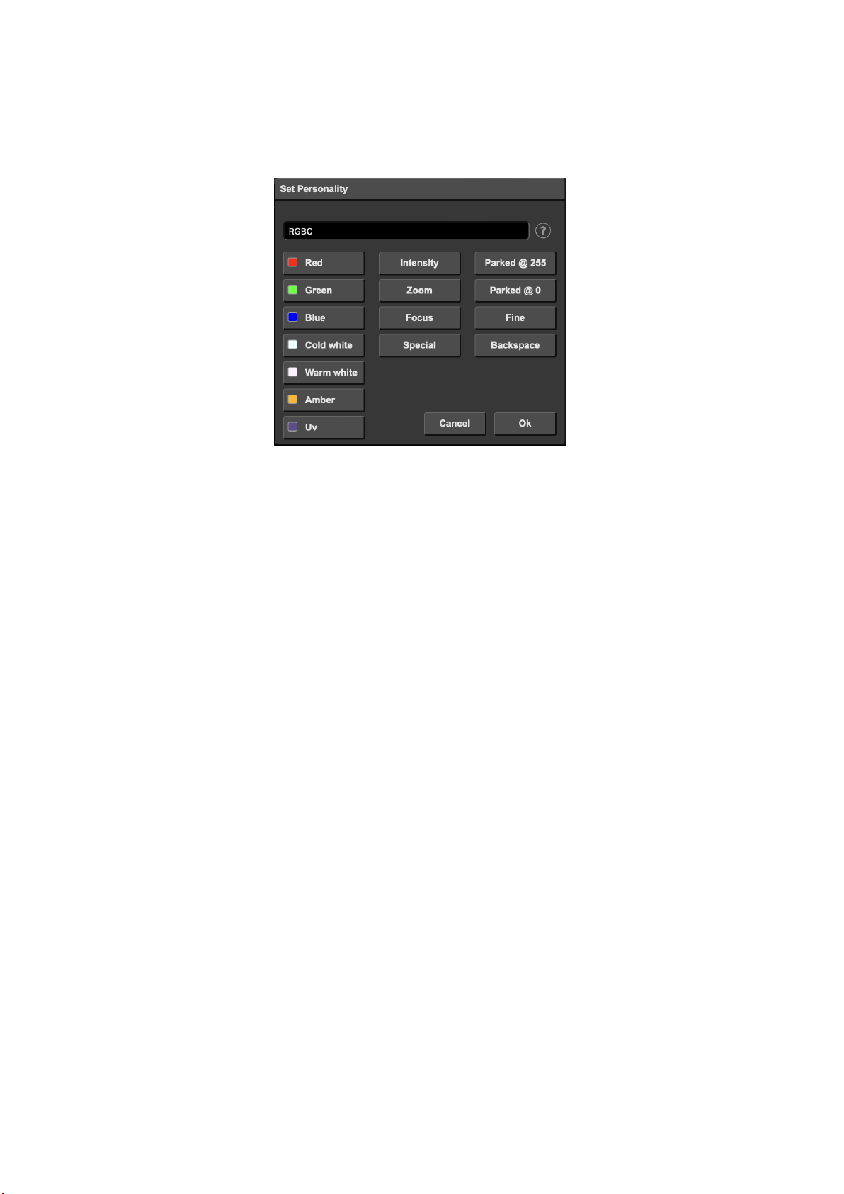
Figure 7.2: Personality dialog
7.4 Discover
Use the Discover button to search for RDM capable fixtures. Fixtures found
via a RDM discovery will show their RDM UID in the patch table.
Before using RDM, RDM needs to be enabled. This can be done on the Patch
or Settings page. By default RDM is disabled.
7.5 Locate
When the Locate checkbox is enabled, then all fixtures will be doused except the
selected fixtures; they will be fully on. This function will help identify selected
fixtures.
46

Chapter 8
Tracks
A Track is a piece of lighting content that can be activated by a playbacks.
Tracks can contain dynamic lighting effects; each track can be a ’DMX recording’
with a certain duration. Of course a static scene can also be stored in a track.
There are three different ways to put the content inside the track. The Console
page allows the user to create and edit a static scene directly via the webinterface. This page also is capable of recording a static scene from an external
DMX, Art-Net or sACN source. The Console page is discussed in detail on page
48.
The second way for storing content into the tracks is done via the Recorder
section; this section of the Track page contains control for recording dynamic
DMX content from external DMX, Art-Net and sACN sources.
Furthermore, it is also possible to create the lighting content using the CueluxPro software and upload it to the CueCore3. This can be dynamic as well as
static content. For more information on CueluxPro see chapter 6, page 40.
8.1 Number of Tracks
The CueCore3 has a fixed number of 128 tracks.
8.2 Track Properties
The Track listing (See figure 8.1) displays the following track properties:
47
Figure 8.1: Tracks
Label The name of the track; this field can be changed by
double-clicking.
Size The number of bytes used by the data inside the track.
Duration The length of the track displayed in
hours:minutes:seconds.milliseconds.
FPS The sample rate of the track displayed in Frames Per Second
(FPS). The sample rate has been chosen during the recording
process and cannot be altered afterwards.
8.3 Console
The Console page (see figure 8.2) allows to edit a track directly through the webinterface, however, a track does need to be a static scene; it should only contain
a single DMX frame. If the track already contains more than one DMX frames
and thus it is a dynamic track, then it can be made static by erasing it. The
track can be edited by selecting the track in the table and then pressing the Open
Console button. This will automatically enable the Track Preview checkbox so
the content that is being edited in the Console page is also outputted live.
The ’Track Preview’ is a useful option to briefly test the content stored in a
track without having to configure a playback for it. Please note that any active
playback will be released when the Track Preview is enabled.
48

Figure 8.2: Console page
Inside the Console page the DMX values of the track can be changed by using the
Command-line interface. The following table offers examples of the supported
commands.
Command Function
1 @ 50 ENTER Sets channel 1 at 50%
1 + 2 @ FULL Sets channel 1 and 2 at 100%
1 THRU 3 @ 0 Sets channels 1 through 3 at 0%
1 THRU 3 + 5 @ 0 ENTER Sets channels 1, 2, 3, and 5 at 0%
ALL @ 100 ENTER Sets all channels in the selected universe at
100%
1 @ + 10 ENTER Increases channel 1 value with 10%
ALL @ − 20 ENTER Decreases all channels in the selected universe
by 20%
By default the Console page presents the DMX values in percentage (%). When
the representation is switched to decimal (by using the ’Decimal’ button) then
the values in the table above would be interpreted as decimal values as well.
E.g. 1 @ 50 ENTER would set the channel at decimal value 50 which relates to
20%.
Instead of setting the values manually, the Console page also offers to make a
snapshot - record the entire scene - from an external DMX, Art-Net or sACN
49

source. The buttons in the Capture section become available when the CueCore3
is receiving the signal of the corresponding protocol. I.e. that the ’DMX’ button
is disabled unless the unit is receiving actual DMX. Please be aware that - once
enabled - pressing one of the capture buttons will overwrite the current channel
levels in all universes.
8.4 Recorder
The Recorder section is used to capture dynamic content from an external source
and store it inside a track. In order to be stored in flash memory, a track requires
to be erased first. It is advised to manually erase the track before starting a
record. This is done by selecting it in the table and then pressing the ’Erase’
button. In case a non-erased track will be directly recorded then the CueCore3
will automatically first erase the track, however, this gives less control over the
timing of the start of the recording, especially in the Manual mode.
Figure 8.3: Recorder section
The icons in the track table visualise the different states of the recorder. The
’trash icon’ indicates a track is being erased. The ’orange dot’ signifies a track
being ready to start recording, this corresponds to the Triggered or Timecode
mode. A ’red dot’ indicates a recording in progress.
8.4.1 Mode
The triggering modes define how the recorder is initiated. There are three
different modes.
50

• The most simple mode is Manual. In this mode the user has to manu-
ally press the ’Record’ button to start and press the ’Stop’ button to end
the recording. Although simple to operate, this mode does not give accurate control over the timing of the begin and end of the recording. Both
human interaction and operation through a web-based user-interface will
introduce some degree of lag.
• An automated way of starting and stopping the recording process is done
in the Triggered mode. One of the data channels is allocated to control
the start/stop. The channel address is denoted by the ’Trigger Channel’
field. It is advised to include this channel in the show programming done
on the external source; a typical lighting console allows accurate timing
of DMX channels which gives fine control over when the recording starts
and ends in relationship to the show content. When using the Triggered
mode pressing the ’Record’ button will prepare the track for recording;
it will be erased when necessary and then stay idle in anticipation of the
trigger channel going high to indicate ’start’. The recording is ended by
setting the trigger channel to 0%.
• The Timecode mode allows for the recording process to be synchronised
by incoming timecode. Pressing the ’Record’ button will prepare the track
for recording; it will be erased when necessary and then stay idle in anticipation of the timecode to start running, it stops when the timecode resets
back to 00:00:00.00. Always record from frame 00:00:00.00. If the content
is supposed to run at a different frame then use the playback’s ’TC Offset’
property to achieve that.
A typical challenge with recording dynamic DMX data is to create a seamless
loop. Often the manual mode will most likely not be sufficiently accurate to
achieve a seamless loop. The triggered mode offers a way to remote control
and make the recording seamless. Alternatively, the lighting content can be designed in CueluxPro instead of recording from an external source, as CueluxPro
automatically takes care of making its content seamless.
8.4.2 Sources
The CueCore3 is capable of recording DMX data from an external source by
using three different protocols:
• DMX
• Art-Net
• sACN
Please consider that the operation of these protocols depend on their properties
the Settings page.
51

8.4.3 Sample Rate
The Sample Rate setting will determine how many samples of the data are taken
per second and stored in memory. This setting variants are 5, 10, 30 and 40
Frames Per Second (FPS). 40 FPS gives maximum quality in terms of smooth
dimming curves. 5 FPS is a low value but useful for slow DMX changes and
consumes much less memory. The 40 FPS setting is recommended unless there
is a reason to reduce the sample rate.
8.4.4 XLR Adapter
The DMX ports on the CueCore3 are mainly used for outputting DMX and
therefor are fitted with female XLR connectors. When using the ports as an
input it is likely that the XLR needs to ’gender change’ into a male connector.
Neutrik offers the NA5MM (figure 8.4), a 5-pin XLR male-to-male adapter for
this purpose.
Figure 8.4: Neutrik NA5MM
8.5 Track Capacity
The CueCore3 has 8GB memory, of which approximately 4GB is reserved for the
tracks. The device uses a compression algorithm to store the data and optimise
the storage for best use. The duration of the recording that the track can hold
depends on several parameters: number of tracks, dynamic lighting content and
the number of DMX channels used. Therefor the maximum duration is hard to
specify, however, some guidance can be provided:
In a typical scenario where 32 moving heads - together consuming 512 channels
- are constantly changing their primary attributes (position, shutter, colour &
gobo) then the memory will hold approx. 16 minutes per track in a 8-track setup.
In a 32-track it will hold 3 minutes per track. Both examples are recording at
40 FPS.
52

In a worst-case scenario with 2,048 channels actively changing to random values
(pixel-mapping content) then a 1-track setup will hold approx. 6m32s, a 16track setup will hold 24s per track. Both examples are recording at 40 FPS.
If the limits of the capacity are reached then there are three different ways to
help overcome this.
• Reduce the ’number of tracks’ in the settings page. Note that the current
track content is lost when changing this setting.
• Reduce the sample rate.
• Spread the content over multiple tracks. They can be linked together later
on the Playback page (For more information go to chapter Playbacks, page
20). This way cross-fades can be generated by the CueCore3 instead of
being recorded.
53

Chapter 9
Playbacks
A playback is capable of activating the lighting content stored in the tracks.
Tracks are merely storage for lighting scenes and effects; the playbacks actually
plays them. The playbacks are located in the Playback page in the web-interface,
see figure 9.1.
Figure 9.1: Playback page
There are 16 playbacks available. Each can contain up to 32 steps, called ’cues’.
A cue will contain a reference to a track plus additional information such as
fade-time and duration. Figure 9.2 illustrates the structure of a playback.
Playbacks can be run independently of each other; they can all start or stop at
different times. It is possible to control the same DMX channels from multiple
54

Figure 9.2: Playback structure
playbacks and have them merged together. Also, it is possible to have each playback control a different set of DMX channels; making each playback responsible
for a different zone. Figure 9.3 shows an example of controlling multiple zones
in a hypothetical restaurant.
Figure 9.3: Playbacks controlling zones in a restaurant
9.1 Precedence
All active Playbacks produce DMX values. These values will be merged together and sent to the DMX output. The precedence setting determines how
this merging is done. Each playback can be set to either HTP (Highest Takes
Precedence), LTP (Latest Takes Precedence) or Priority.
55

HTP is the most common choice in precedence. With HTP the output of all
playbacks is compared to each other; for each DMX channel the level is set to
the highest value found in that particular channel amongst all playbacks. The
table below shows an example of HTP merging.
Playback 1 Playback 2 Playback 3 Merged Output
Channel 1 0% 0% 25% 25%
Channel 2 100% 0% 25% 100%
Channel 3 0% 0% 0% 0%
Channel 4 0% 100% 25% 100%
In the LTP approach only one playback is active amongst all LTP playbacks.
The output of that active playback is included in the merge with all HTP
playbacks. All other LTP playbacks are ignored. Which LTP playback is active
is determined by which playback is started latest, or which received a Go+
command latest. Please consider figure 9.4.
Figure 9.4: Playback precedence
If there is a playback active with its precedence set to Priority then all other
playbacks are ignored. When there are multiple Priority playback then those
will be merged together according to the HTP principle.
9.2 Playback Properties
Each playback provides a set of properties that can be used to customise the
playback’s behaviour. Some properties are changed by double-click.
56

Label The name of the playback.
Intensity The output level of the playback.
Typically, a DMX recorder stores the values of the channels
without knowing its functions. When reducing the output
level at the Playback all channels are reduced, also the ones
that contain information other than intensity/dimmer levels.
This has the undesired effect that RGB or Pan Tilt channels
are also affected, whereas ideally only the intensity levels
should be lowered. This is a challenge all DMX recorders
have. The CueCore3 overcomes this issue by using the
information from the Patch page to check which channels
control intensity, only those channels will be dimmed.
If no fixtures are patched, then all channels will be dimmed.
Rate The speed of the playback. By default, it is set to 0%. It can
go up to 100% (faster) and down to -100% (slower).
Release When released the playback can fade out to zero. This release
time defines how long this fade out will take. Setting it to 0s
will result in an instant release.
TC When enabled, the playback is synchronised to the current
timecode (TC). By default, TC is disabled. Note that the
Settings page provides a field for selecting the timecode
protocol, e.g. ’internal’ or ’Art-Net’.
TC Offset Specifies at which timecode frame the playback starts.
Precedence Determines how the output of the playbacks is merged
together, as explained on page 55.
MFade Normally the fade time between cues is determined by the
’fade’ field in the cue properties. When Mfade is enabled then
the playback will ignore the cue’s fade times and use the
master fade time for all its cues.
Repeat This property determines what the playback does when it
finishes the last cue.
Loop: Will start over from the beginning.
Bounce: Will make it traverse back to the beginning, and it
will keep going back and forth.
Random: The order of the cues will be random.
Off: The Playback will automatically release when reaching
the end of the cues.
Cue Current/Total of Cues. Indicates which cue is currently active
and indicates the total number of cues in the Playback.
The intensity and rate properties are not stored in the CueCore3’s internal
flash memory. It is expected that these properties can change often during the
operation of the CueCore3 and could consequently wear out the flash memory.
57

A consequence of not storing these properties is that after a power cycle their
levels will be reverted to the default values. If the intensity or rate requires to be
permanently set to a value other than the default value then it is recommended
to use the Show Control page and create an action in the ’System’ action list.
This action can have its trigger set to ’Startup’ and contain tasks to set the
playback’s intensity and rate to the desired values.
9.3 Cue
A cue is a step inside a playback. A playback can contain up to 32 cues. A
cue does not contain a lighting scene, rather, it refers to a track which does
contain the lighting scenes. It is possible for multiple cues to refer to the same
track. The cue does contain information on how long the lighting scene should
be played and if it should be cross-faded from the previous cue.
Figure 9.5: Cues
Each cue provides the following properties:
58

Track A reference to the track that will be played in this step.
Fade The cue will fade from the current levels to its programmed
levels. The time it takes to cross-fade is specified by ’Fade’.
When the fade is set to 0 then there will be no cross-fade; the
values will change instantly.
Duration Determines how long the cue will be active before traversing to
the next cue. This is the time between the completion of the
cross-fade into this cue and and the start of the cross-fade to
the next cue.
The duration field accept not only ’time’ input such as ”.5”
”30s” or ”1m15”, it also accepts ’number of cycles’; the
playback can run the cue ”1x” or ”10x”. This is particularly
useful when the track referred to by the cue contains a
(seamless-)looped effect. Please note that if the track contains a
static scene; i.e. the track only holds a single DMX frame, then
running it for a number of cycles will create a very short cue as
a single DMX frame only takes 25ms.
The third option for the duration field is to input ”halt”. In this
case the cue will continue to run indefinitely; it requires a Go+,
Go-, Jump or Release command to traverse to the next cue.
The Playback page provides the following buttons to edit the cues:
• Add: Will add a new empty cue.
• Remove: Will remove the selected cue
• Up: Will move the selected cue up a position.
• Down: Will move a selected cue down a position.
• Fade: Will open a pop-up window where you can set the fade time.
• Duration: Will open a pop-up window where you can set the duration.
9.4 Transport
The transport section offers buttons to control the playbacks.
Go+ Jump to the next cue.
Go- Jump to the previous cue.
Release Deactivates the selected playback. Press and hold to release all
playbacks.
9.5 Master
The master section provides features that are applied to all playbacks.
59

Intensity The master intensity works like a theatrical ’grand master’; it
dims the output of all playbacks taking their individual
intensity setting into account.
Rate The master rate will control the play speed of all playbacks;
with taking their individual rate settings into account.
Fade The master fade time overrides the fade time of all cues. This
only applies to playbacks that have ’MFade’ enabled.
Similar to some of the playback properties, the master properties are not stored
in the internal flash memory. Please refer to the discussion on page 57.
60

Chapter 10
Show Control
The CueCore3 can interact with the outside world;
Another option is integrating the CueCore3 with other systems, by using the
various protocols it can receive to trigger its functionality. The Show Control
page (See figure 10.1) enables this kind of programming to be made.
Figure 10.1: Show Control page
The Show Control page presents a system of actions. A signal that the CueCore3
should to respond to or perhaps convert into some other signal, needs to be
expressed in an action. Before programming actions please consider the show
control structure in figure 10.2.
The CueCore3 is capable of listening to various protocols. These available protocols are listed in Sources, however, the CueCore3 can only actively listen to 8
61

Figure 10.2: Show Control structure
protocols at once. The active protocols are listed in Actionlists. Each actionlist
can contain actions. Within a protocol/source each individual signal requires
its own action. For example, when listening to channel 1 and 2 on the incoming
DMX, the DMX actionlist needs two actions; one for each channel.
Inside the action we define the trigger and tasks. The trigger specifies for which
signal to filter. In the above DMX example the trigger would be set to ’channel
1’ and ’channel 2’ respectively. The tasks determine what the CueCore3 will do
when this action is triggered. Several tasks can be placed in the action. There
are tasks available for a wide range of CueCore3 features and external protocols.
Task types are detailed in Appendix B on page 114.
Please consult the API appendix on page 128 before implementing incoming
OSC or UDP messages; the API already exposes typical functionality through
OSC and UDP and therefor it might not be necessary to implement custom
messages.
10.1 Sources and Actionlists
The Sources listing presents all protocols that the CueCore3 is capable of receiving. It also includes internal features that can create events that can be used for
triggering actions, such as the calendar-scheduler. These sources are available,
however, they will only be actively listened to once moved to the action-list
table.
62

UDP Incoming UDP network messages
TCP Incoming TCP network messages
OSC Incoming OSC network message
DMX Input DMX received on one or more of the DMX ports (switch
port to input in the settings page)
Art-Net Incoming Art-Net DMX data
sACN Incoming sACN DMX data
Timecode Timecode signal, specify the incoming timecode protocol on
the Settings page.
Kiosc Triggers from Kiosc. For each Action various controls can
be chosen such as buttons and sliders, colour picker etc. The
order of the actions will control the arrangement in Kiosc.
Scheduler Triggers based on time, date, weekdays, sunrise, sunset &
timespan.
Playback Events generated by the playbacks
Randomiser The randomiser can generate a random number
System Events such as ’Start up’
Variable The Variable source works in combination with the variable
task (For more information about the Variable task please
refer to Task Types). The Variable task will set a value of
which an enabled actionlist type with Variable as Source
will use as a trigger. The CueCore3 will keep the values of
the 10 variables even after shut down so long as the RTC
battery is not empty.
Timer There are 4 internal timers in the CueCore3. An event will
be raised when a timer expires. Timers are set and
activated by the Timer tasks.
Actionlist Gives an event when an actionlist is enabled or disabled.
User List 1-4 These actionlists will never trigger an event, however, they
are useful for advanced programming.
Actionlists can be temporarily suspended by disabling their checkbox in the
Show Control page. There is also a task available to automate changing the
state of this checkbox.
10.2 Actions
Actions are executed when a certain signal is received. This signal is defined by
the trigger. A trigger is always relative to the actionlist the action belongs to.
For example, when the trigger-type is set to ’Channel’ then it refers to a single
DMX channel if the action is placed inside a ’DMX Input’ list and it means a
63

single Art-Net channel if the action resides in an Art-Net actionlist.
Figure 10.3 shows the screen when editing an action.
Figure 10.3: Edit Action dialog
A trigger is determined by the trigger-type, trigger-value and trigger-flank fields.
Although these fields are not applicable for all actionlists and are therefor sometimes omitted in the web GUI. The trigger-type field specifies what kind of signal
the action will be triggered by.
For example, when making an action in the Scheduler list there is the choice
between ’DateAndTime’ and ’WeekdayAndTime’ trigger-types. The triggervalue specifies the actual signal value. In the schedular example the trigger-value
could be set to ”2016-03-24 11:00” or ”Weekend 10:00” respectively.
In some actionlists actions do also need to specify the trigger-flank. The flank
further specifies the value that the signal should have before triggering the
action. For example, when an action is triggered from the Kiosc list, the flank
will determine whether to trigger only when the button goes down or only when
it goes up. Appendix A provides an overview of the available trigger-types.
An actionlist can have up to 48 actions, system-wide there is a maximum of 64
actions.
10.3 Tasks
Tasks are added to an action in order to specify what to do when it gets executed.
Up to 8 tasks can be included in an action, systemwide there is a maximum of 128
tasks. The tasks are executed in the order of the list. There is a wide selection of
tasks available to choose from, they include altering any of the internal software
features like playbacks and recorder but also sending out messages through any
of the supported protocols. The tasks are organised in categories. Once a task is
chosen from these categories each task allows for further choice between several
Features and Functions. Tasks contain up to two parameters that might be
required for its execution.
64

If the event that triggers the action passes a parameter along then this parameter
can be used in a task. The Set function makes a task use a fixed value, however,
when using the Control function then the trigger’s parameter is used. This is
very useful for conversions between protocols.
For example when converting 0-10V to DMX the GPI action specifies the port
(e.g. #1) and flank (e.g. OnChange) on which it will trigger. The actual 0-10V
level sampled on the GPI port will be passed along and fed into the action.
Then when a task (e.g. DMX) uses the function Control this 0-10V level will
be used for setting the DMX value.
A task can be tested by selecting it and pressing the ’execute’ button in the
Edit Action dialog. The complete action can also be tested; go to the Show
Control page, select the action and press the Execute button.When either of
these Execute buttons are used, the source of the Control value for tasks will
be the Execute button. The result will depend on the chosen task and feature,
but will most likely be 100%, 1.0, or 255 when pressed and 0%, 0.0, or 0 when
depressed.
Appendix B provides a detailed overview of the available tasks, features, functions and parameters.
10.4 Templates
The Show Control page presents a list of templates. A template is a set of actionlists, actions and task. These templates configure the CueCore3 to perform
typical functions; for example convert Art-Net to DMX or control the 6 playbacks through OSC. The templates thus save time; otherwise actions should
have been set up manually. They can also function as a guide to soften the
learning curve on actions; a lot can be learned from adding a template and then
exploring the actions and tasks it created.
Please note that some templates require settings to be changed in the settings
page; for example the ’Receiving Art-Net’ template needs the DMX outlets to
be set to outputs in order to achieve an Art-Net to DMX conversion.
Appendix C gives an overview of the available templates.
10.5 Variables
Variables are part of the show control system in the CueCore3. There are 20
variables and each can hold a value in the range of [0,255]. These values can
be manipulated by tasks and can be used for advanced action programming.
Variables can be added as sources in order to have actions triggered when a
variable changes value.
You can see the status of the variables in the monitor page, as discussed on page
79.
65

The values of the variables are stored in the same battery backed-up memory
as the RTC; it will hold the values between power cycles, if the time between
power-on does not exceed a few days.
To illustrate the use of variables, please see the following example in which
a variable is used to keep track of the cue index between power-cycles. (By
default, the CueCore3 does not remember which playback or cue was active after
a power-cycle.) For simplicity, we assume that an external system is selecting
cues inside the CueCore3 by sending UDP messages.
• Program a playback to contain 4 cues.
• Add the Variable source and insert one action. If the variable changes
then jump to the appropriate cue by adding a Playback task to this action.
• Have the external system use the UDP API to set the variable values in order to select a cue. The appropriate API message is
core-va-1-set=<integer> where integer is the cue index.
66

• Add the System source and insert one action. At start-up, trigger a
variable ’change’ in order to jump to the previously selected cue.
10.6 Timers
The show control system of the CueCore3 features four internal timers. By
using tasks, the timers can be set to certain durations and they can be started.
Once started the timers will countdown to zero. When the timer reaches zero
it will generate an event that can be captured by using the Timer actionlist.
Please note that the timer values are not stored between power cycles. You can
see the status of the four timers in the monitor page, under Timers.
The next example will show a timer being used to regularly send a UDP message
to an external system in order to notify that the CueCore3 is still ’alive’.
• Setup and start the timer at power-on. This is done by creating an action
in the System actionlist.
67

• If the timer expires then send the UDP message and restart the timer.
This is done by creating an action in the Timer actionlist.
10.7 Randomizer
The Randomizer is an internal software feature that can generate a (pseudo)random number. This is useful for having an event trigger a random lighting
scene in a themed environment. The randomizer is activated by the Randomizer
task. The result of the randomizer’s calculation can be obtained by catching
the event in the Randomizer actionlist.
The following example shows how to use a Kiosc button to trigger a random
cue.
68

• Inside the Kiosc actionlist is a button-action. This triggers the task
Randomizer, which is set to a range of between 1 and 6. (Parameters 1
and 2 of the task Randomizer)
Kiosc will just simply show one button.
69

• Next in the actionlist Randomizer there is an action triggered by the
Randomizer. The task Playback, controlled by the result of the Randomizer, jumps to a cue in Playback 1 (Parameter 1 of the task Playback).
• When the Kiosc button is pressed the Randomizer picks a number
between one and six, as defined in the Randomizer task. The Playback
task receives this number and triggers the corresponding cue.
10.8 User Lists
Normally a source is connected to a communication port, protocol or software
feature. Actionlists will be triggered as soon as an event happens in a source.
There is an exception; the User Lists are not connected to any source and
therefor will not be triggered by any communication or other event. The purpose
of User Lists is to have extra actionlists containing actions which can be triggered
by explicitly linking to it. See page 122 for details of the Link feature in the
Action task.
70

The following example demonstrates the use of a User List. Imagine a scenario
in which the GPI is used to change between three lighting scenes. To prevent
unauthorised use a key-contact-closure is connected to GPI pin 4; the first three
GPI should only respond when pin 4 is a closed contact by using the key.
• Create a playback with three cues
71

• Create an User List with three actions.
Set each action to jump to one of the three cues in playback 1.
72

• Add an GPI actionlist and link the first three GPI ports to the action in
the User List.
• Use the fourth GPI port enable or disable the User List.
For brevity the state of the GPI port 4 is ignored at start-up. Usually additional
actions are created to Refresh this port on start-up.
73

Chapter 11
Protocol Conversion
The CueCore3 is fitted with several communication ports and additionally supports various Ethernet-based protocols. Although some protocols are predominantly used for triggering the internal playbacks (such as GPI, MIDI, UDP,
OSC, etc.) and some other protocols are mainly used for recording (such as
DMX input, Art-Net and sACN) the CueCore3 is capable of converting one
protocol into another. This chapter provides an insight on which conversions
are possible and how to set them up.
All possible conversions can be organised into two categories: Converting Control Protocols and Converting DMX Universe Protocols.
11.1 Converting Control Protocols
The first category of conversions comprise the protocols typically used for triggering or transporting one piece of information. The following table shows these
protocols and what kind of information they are able to carry.
74

Control Protocols Information
Digital GPI On/Off
Analog GPI percentage [0%,100%]
MIDI number [0,127]
UDP -
TCP -
OSC percentage [0%,100%], number, string, colour, On/Off
DMX number [0,255]
Art-Net number [0,255]
sACN number [0,255]
Although DMX, Art-Net and sACN are dedicated lighting protocols and naturally fit in the next category, their individual channels lend themselves well for
conveying control messages.
Setting up a conversion is done in the Show Control page. First add the incoming protocol from the ’Sources’ table into the ’Action list’ table. Then add
an action to this new action-list. Inside this action the trigger-flank field (if
visible) should be set to Change; as this action should be triggered every time
the incoming signal changes. Furthermore, a task need to be added, the tasktype determines which protocol is the output of our conversion. It is important
that the ’function’ in this task is set to ’Control’. This will make sure that the
output is not a fixed value, rather it will output the information received from
the incoming signal.
Please consider two examples. Figure 11.1 shows a conversion between Digital
GPI and OSC. This example assumes the GPI Port 1 is set to ’Digital’ on the
Settings page.
(a) Step 1
(b) Step 2
Figure 11.1: Conversion from GPI to OSC
Figure 11.2 shows a conversion between MIDI and DMX. This example assumes
75

the DMX Port A is set to ’Output A’ on the Settings page.
(a) Step 1
Figure 11.2: Conversion from MIDI to DMX
(b) Step 2
11.2 Converting DMX Universe Protocols
This category includes all protocols that carry a DMX Universe (a block of 512
DMX channels). These protocols are DMX, Art-Net, sACN and to some extend
KiNet. The CueCore3 is capable of receiving a complete DMX universe from
one protocol and sending it out on a different protocol. Furthermore, it is able
to merge DMX universes from multiple sources into one output protocol. All
this is done with a minimal amount of configuration in the CueCore3. The
following table lists examples of the conversions that can be made.
Example DMX Universe Conversions
DMX ->Art-Net
Art-Net ->DMX
DMX ->sACN
sACN ->DMX
DMX ->KiNet
Art-Net ->sACN
It is also possible to create combinations of the examples above. For instance
you could set up a conversion from DMX to both Art-Net and sACN. Or merge
incoming Art-Net and sACN together into the DMX output. Also, at any point
it is possible to merge the incoming DMX data with the data generated by the
internal playbacks.
To set up the conversion go to the Show Control page and choose the incoming
protocol from the ’Sources’ table and add it to the ’Action lists’ table. Then add
an action for each DMX Universe you wish to convert; e.g. when converting two
DMX ports to Art-Net it requires two action to programmed. The trigger-type
76

in the actions should be set to ’Universe’ to make the CueCore3 process the 512
channels as a whole rather then process individual channels. Each action should
contain a DMX-task with the ’feature’ set to ’Universe’; all DMX Universe data
is first being copied into the CueCore3’s internal DMX buffer. From this buffer
it can be copied to the DMX outlet or the other protocols such as Art-Net and
sACN. Figure 11.3 provides a schematic for this data flow.
Figure 11.3: DMX merging data flow
The function needs to be set to Control HTP.
Function
Control HTP Highest Takes Precedence
Clear
All channels are compared and the highest levels are used for the merged output
(HTP precedence).
The additional ’Clear’ function is not related to the data merging precedence;
it is just a function to clear the whole universe to zero.
Please note that the ’Templates’ table provides pre-programmed configurations
for the most popular conversions.
A very typical conversion that can illustrate as an example is to convert Art-Net
universes 0.0 and 0.1 to DMX output A and B respectively. Figure 11.4 shows
action-list, figure 11.5 show the contents of ’Action 1’ and figure 11.6 show the
required configuration of the Settings page.
77

Figure 11.4: Converting Art-Net to DMX step 1
Figure 11.5: Converting Art-Net to DMX step 2
Figure 11.6: Converting Art-Net to DMX step 3
78

Chapter 12
Monitors
This page allows the user to inspect the incoming and outgoing data, both
DMX-type data (See figure 12.1) as well as control messages (See figure 12.2).
Monitoring incoming and outgoing data can help the user troubleshoot during
programming.
Figure 12.1: DMX Monitor
In the Monitor page three different sources of input can be found (DMX, ArtNet and sACN), along with the control input and output sources (TCP, UDP
and OSC). On the right side of the page there are the universes were the user
can swap between the two of them or choose a preferable unit for displaying the
requested information.
The Monitor page also presents an overview of timer and variable values. See
figure 12.3
79

Figure 12.2: OSC Monitor
The variables can be renamed for convenience. It also possible to set the variable
value directly in this screen.
80

Figure 12.3: Timer & Variable Monitor
81

Chapter 13
Settings
The CueCore3’s settings are organised into sections, see the Settings page figure
13.1. This chapter will discuss each section.
13.1 General
You can change the CueCore3’s label. This label can be used to distinguish the
unit in a set-up with multiple devices.
By enabling the Blink checkbox the device’s LED will blink to help to identify
it amongst multiple devices.
The API commands discussed in appendix D start with a prefix that is set to
core by default. When using multiple devices from Visual Productions it can be
useful to assign unique labels to these prefix, especially when using broadcasted
messages. Read more about feedback loops in paragraph D.4.1.
Unauthorised users can be prevented from making changes to the CueCore3 by
enabling the Password protection. Once enabled, the password can be disabled
via the web-interface (using the Disable button) and the reset button (see figure
5.2). Long-press the reset button to disable the password protection; this will
also revert the unit’s static IP back to the default factory settings.
13.2 IP
The IP fields are for setting up the IP address and subnet mask of the CueCore3.
The Router field is only required when Port Forwarding is used. You can also
enable or disable the DHCP feature (For more information see chapter 5 at page
36).
82

Figure 13.1: Settings page
Figure 13.3: IP Settings
13.3 Slaves
This section enables the master-slave synchronisation.
83

Figure 13.2: General Settings
Figure 13.4: Slaves Settings
The master-CueCore3 should specify the IP addresses of its slaves. When the IP
is indicated in white then the master-slave connection is established, otherwise
the IP is indicated in orange. For creating a system with more than four slaves, a
broadcast IP can be set. A message sent to a broadcast address may be received
by all network-attached hosts. A typical broadcast IP address is 192.168.1.255,
however, this depends on the subnet used.
The slave-CueCore3 units require the ’Allow control by master’ checkbox to be
enabled. Enabling ’Allow control by master’ checkbox will cause playback data
to be overwritten.
13.4 Date & Time
The date and time of the RTC can be set here. The clock has a back-up
battery to keep the time during a power down. Daylight Saving Time (DST) is
supported for the regions Europe and United States.
The Time Server field allows a NTP server to specified. At start up, the
CueCore3 will fetch the time and date from this server. Additionally, an action
can be used to fetch the time. The DST and the Coordinated Universal Time
(UTC) are taken into account when obtaining the time for the NTP server.
The following table lists suggested NTP servers.
84

Figure 13.5: Date & Time Settings
Continent Server
North America 64.90.182.55
South America 201.49.148.135
Europe 216.239.35.8
Africa 196.23.245.74
Asia 133.100.9.2
Australia 137.92.140.80
13.5 Location
The astronomical clock in the CueCore3 calculates the sunrise and sunset times
based on day of the year, latitude, longitude and UTC. The latitude and longitude values define the position in the world and should be entered in degrees.
The latitude value should be positive for North and negative for South, the
longitude should positive for East and negative for West.
The website http://www.findlatitudeandlongitude.com/ can help discover the
latitude and longitude values for the current location. The time-zone and perhaps daylight saving time of the current location is expressed in the UTC value.
UTC is - in this context - equivalent to Greenwich Mean Time (GMT).
For example, Visual Productions’ HQ is based in the city of Haarlem, the
Netherlands. During the winter the UTC equals +1 and in the summer during
day light saving time it is set to +2. So, the settings for the Visual Productions’
HQ are shown in Figure 13.6.
The Offset fields allows to shift the sunrise and sunset triggers, both earlier and
later. For example, to have a trigger half an hour before sunrise set the offset
to -00:30.
85

Figure 13.6: Location settings
13.6 OSC
External equipment sending OSC messages to the CueCore3 need to be aware
of the number specified in the ’Port’ field. This is the port the CueCore3 listens
to for incoming messages.
Figure 13.7: OSC Settings
The CueCore3 will send its outgoing OSC messages to the IP addresses specified in the ’Out IP’ fields. Up to four IPs can be specified here. Use the ’ipaddress:port’ format in these fields, e.g. ”192.168.1.11:9000”. If a field should
not be used then it can be filled with IP 0.0.0.0:0. It is possible to enter a broadcast IP address like 192.168.1.255 in order to reach more than four recipients.
Enabling the Forward checkbox will have the CueCore3 copy every incoming
OSC message and send it the addresses specified in the ’Out IP’ fields.
13.7 Timecode
The CueCore3 can receive SMPTE, MTC and Art-Net timecode. This section
allows to choose one of these protocols as the timecode source. Alternatively,
the CueCore3 also has ’internal’ timecode; a timecode generated by the unit
itself. Synchronisation of playbacks and actions depend on this choice.
86

Figure 13.8: Timecode Settings
The timecode freewheel will allow continue for some frames after the timecode
source stops. ”Forever” can be entered to continue when no timecode is received.
13.8 Purple Cloud
The CueCore3 can be remotely monitored via the Purple Cloud.
Figure 13.9: Cloud Settings
The Share Analytics checkbox needs to enabled - as well as an Internet connection - in order to establish a connection with the Purple Cloud. By enabling
the Share Analytics checkbox you agree to having anonymous statistics and usage data collected by the cloud. Visual Productions will only use this data for
improving its products.
The Cloud ID should contain your ID as generated by the Purple Cloud. This
ID can be found on the cloud’s Account page. This ID connects the CueCore3
device to your Purple Cloud account. The Cloud ID is displayed in yellow in
case no match has been found in the Purple Cloud ’s database.
13.9 TCP/IP
Defines the listening ports for TCP and UDP messages. External systems intending to send TCP or UDP message to the CueCore3 need to know the unit’s
IP address and this port number. By default both ports are set to 7000.
87

Figure 13.10: TCP/IP settings
13.10 DMX
The DMX settings specify whether the DMX port is an Input or output.
Figure 13.11: DMX settings
When the Slow DMX checkbox is enabled, the CueCore3 will slowdown the rate
at which it sends out DMX. This is done to facilitate DMX fixtures that have
difficulties keeping up with the optimal DMX transmission rate.
When programming a show that does not use all DMX universes it can be useful
to set multiple DMX ports to the same universe. This can make cabling more
efficient and perhaps prevent the need of a DMX splitter. For example, when
using only 512 channels bothDMX ports can be set to ’Universe A’.
RDM can be disabled by using the Enable RDM checkbox. This checkbox is
repeated on the Patch page.
13.11 Art-Net
The Art-Net feature in the CueCore3 supports 4 universe out and 4 universes
in.
These universes can be mapped to any of the 256 available universes in the
Art-Net protocol. The universe is entered in the ’subnet.universe’ format, i.e.
the lowest universe number is written as ’0.0’ and the highest universe number
is denoted as ’15.15’. The outgoing Art-Net transmission can be disabled by
entering ’off’ in the output fields.
88

Figure 13.12: Art-Net settings
The Destination IP determines where the outgoing Art-Net data will be sent to.
Typically, this field contains a broadcast address like 2.255.255.255 which will
send the Art-Net data to the 2.x.x.x IP range. Another typical Art-Net broadcast address is 10.255.255.255. When using broadcast address 255.255.255.255
then all the devices on the network will receive the Art-Net data.
It is also possible to fill in a unicast address like 192.168.1.11; in this case the
Art-Net data will be send to one IP address only. This keeps the rest of the
network clean of any Art-Net network messages.
13.12 sACN
The CueCore3 supports 4 incoming sACN universe and 4 outgoing universe.
The universe field should hold a number in the range of [1,63999]. Outgoing
sACN transmission can be disabled by entering off into the sACN output field.
Figure 13.13: sACN settings
Set priority field to control the priority level of the output universe. The priority
can be set from 0 (lowest) to 200 (highest).
89

13.13 KiNet v1
The CueCore3 features transmission of DMX data via KiNet; it supports KiNet
protocol version 1.
Figure 13.14: Kinet Settings
13.14 GPI
The GPI ports can be configured either as digital (contact-closure) or as analog
(0-10V) input.
In case a port is set as analog and the signal supplied falls within the 0-10V
range (e.g. 1-5V) then it is recommended to calibrate to port in order to map
the minimal voltage to a logical 0% and map the maximum voltage to 100%.
To perform a calibration first enable the Calibrate button, then bring the incoming signal to the minimum level, bring the signal to the maximum level and
then close the calibration process by clicking the Calibrate button again.
Figure 13.15: GPI Settings
Do not apply more than 10V to the GPI port, as this could cause permanent
damage.
90

Figure 13.16: Timespan settings
13.15 Timespan
The Timespan section allows for four periods of time to be defined. The beginning and end of the time periods will trigger actions in the show control
page.
An advantage of Timespans over normal scheduler actions is that Timespans are
power-cycle safe. When the CueCore3 is without power during the moment of
a normal scheduler trigger then it will miss that trigger. Timespans, however,
will still receive the trigger once the power is restored after the moment has
occurred.
Timespans are ideal for defining periods of time during a year (like Christmas
or Easter) or periods during the day (like opening times).
When entering the date and time data, XX’s can be used to signify a ’don’t
care’. This allows for easily programming of yearly, monthly or daily reoccurring
events.
91

Chapter 14
Purple Cloud
The Purple Cloud is a cloud service created by Visual Productions. It allows
CueCore3 and Kiosc Touch devices to be remote monitored via the internet.
The Purple Cloud is accessible via www.visualproductions.nl. Registration
is free of charge.
Figure 14.1: Account settings
Organisations can register an Account - see figure 14.1 - and add their team
members as Users.
To connect your devices to your cloud account, you would need to take the
following steps:
92

1. Enable Share Analytics
Enable the checkbox in the CueCore3’s Settings page. See also page 87.
2. Enter the Cloud ID
This ID can be found on the Purple Cloud’s account page. Copy this ID
into the Cloud ID field on the Settings page of the CueCore3.
Your device should now be visible in the Devices page of the Purple Cloud, see
figure 14.2
Figure 14.2: Devices overview
The CueCore3 can now be monitored by double clicking the device in the table.
This brings up a pop-up window that mimics the CueCore3’s web-interface.
93

Figure 14.3: Remote monitoring a CueCore3
94

Chapter 15
vManager
A free-of-charge software tool called vManager has been developed to manage
the devices. vManager allows for:
• Setup the IP address, subnet mask, router and DHCP
• Backup and restore the device’s internal data and settings
• Perform firmware upgrades
• Set the real-time clock of the CueCore3 (The computer’s date and time
will be used)
• Identify a specific device (in a multi device set-up) by blinking its LED
• Revert to factory defaults
Figure 15.1: vManager
95

The following section explain the buttons in the vManager, as seen in figure
15.1.
15.1 Backup
Backups of all the programming data inside the device can be made. This
backup file (an XML) is saved on the computer’s hard-disk and can be easily
transferred via e-mail or USB stick. The data of the backup can be restored via
the Restore button.
Figure 15.2: Creating a backup
Apps distributed by app stores are not allowed to access files outside this designated location. It is important to know where vManager is storing its files, in
case you wish transfer a backup file to memory stick or dropbox.
The designated file location differs per operating system and is likely to be a
long and obscure path. For this reason, vManager provides you with a shortcut
to the correct file location. A Folder button can be found in the file related
dialogs. Clicking this button will open a file browser at appropriate folder.
15.2 Upgrade Firmware
To upgrade the firmware, first select the device and press the Upgrade Firmware
button. The dialogue allows for selecting from the list of firmware versions
available.
Warning: Make sure the power to the device is not interrupted during the
upgrade process.
15.3 Set Date & Time
The computer’s date and time can be quickly copied to the unit by selecting a
device and clicking the Set Date & Time button. Not all Visual Productions
devices feature an internal real-time clock.
96

Figure 15.3: Firmware upgrade
15.4 Blink
The device’s LED can be set to Blink fast for identifying the particular unit
amongst multiple devices. The blinking is enabled by double-clicking on a device
in the Devices list or by selecting a device and then clicking the Blink button.
15.5 Factory Defaults
All the user data like cues, tracks and actions are stored in the on-board flash
memory. They will be completely erased and all settings will reverted to their
defaults by pressing the Factory Defaults button. This action does not affect
the device’s IP settings.
15.6 RTC Calibration
The CueCore3 features an internal real-time clock (RTC) that is used for generating scheduler triggers (date, time, sunrise, etc). In case that the clock is
drifting, i.e. slowly falling behind or getting ahead of the real time, then it can
be calibrated again using the vManager. The procedure is as follows:
1. Select the CueCore3
2. Click on the Start RTC Calibration button
3. wait approximately 30 minutes
4. Click on the Stop RTC Calibration button
5. Apply the recommended calibration value in the dialog (figure 15.4)
15.7 Reboot
The Reboot button allows you to remotely restart the device. This is useful for
testing the unit’s behaviour after a power-cycle.
97

Figure 15.4: Apply calibration value
15.8 Installing vManager
The vManager app is available on a wide range of operating systems, both
mobile and desktop.
The softwares is distributed through app-stores to take advantage of receiving
future software updates automatically.
15.8.1 iOS
vManager can be downloaded from the Apple iOS app-store at https://itunes.
apple.com/us/app/vman/id1133961541.
15.8.2 Android
vManager can be found on the Google Play store at https://play.google.
com/store/apps/details?id=org.visualproductions.manager.
Android 5.0 or higher is required.
15.8.3 Windows
Visit the Microsoft store at https://www.microsoft.com/en-us/p/vmanager/
9nblggh4s758.
Windows 10 is required.
15.8.4 macOS
Visit the Apple macOS app store at https://apps.apple.com/us/app/vmanager/
id1074004019.
macOS 11.3 is recommended.
98

15.8.5 Ubuntu
You can acquire the vManager from Snapcraft at https://snapcraft.io/
vmanager.
Alternatively, it can be installed by using the command-line:
snap find vmanager
snap install vmanager
To update the apps later on via the command-line type:
snap refresh vmanager
Ubuntu 20.04 LTS is recommended. The software is only available for the
amd64 architecture.
99

Chapter 16
Kiosc
Kiosc is an application for creating custom touch screen user-interfaces for the
range of lighting controllers from Visual Productions. Kiosc is designed to have
no editing capability, making it a fool-proof interface that can safely be presented
to non-technical operators.
Figure 16.1: Kiosc
Kiosc is the ideal way to remote control our solid-state lighting controllers like
CueluxPro, CueCore1, CueCore2, QuadCore, IoCore1, IoCore2, LPU-2, DaliCore, B-Station1 and the CueCore3. Kiosc enables you to choose scenes or
presets, set intensity levels or choose RGB colours.
You can also use it to control third-party AV equipment. Kiosc speaks UDP
and OSC.
100
 Loading...