

VISUALINT VI-3000-DOM-S-WH, VI-3000-BUL-S-WH Quick Start Manual
— 9 — — 10 — — 11 —
— 12 — — 13 — — 14 —
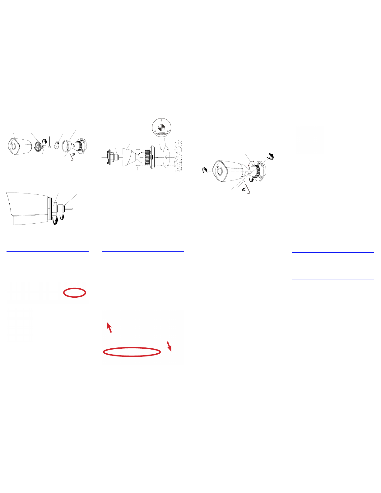
Installing the Bullet
Loosen (but do not remove) the set screw on the
side of the camera. Remove the camera assembly
from the base. Remove the rear cover. Open the
waterproof lock and remove the lock nut and
rubber gasket.
Using the adhesive template, drill 4.5mm holes
for the wall anchors (marked B on the template).
If needed, drill a hole for the cabling (marked A).
If the cabling will run along the wall, mount the
camera to a junction box.
If mounting on a pole, slip the straps through
the slits on each side of the base.
Slide the cabling through the rubber gasket and
the waterproof lock.
Insert the wall anchors, then place the camera
base in place and secure with screws.
Connect the network cable. If you are not using
POE, connect the power line.
Reattach the rear cover. Insert the rubber gasket
into the waterproof lock. Ensure the cabling is
reasonably taut, then tighten the lock to create a
good seal.
Attach the camera to the base by aligning the
unlocked icons on the housing and base, then
twisting until the locked icons align. Adjust the
camera’s aim, then tighten the set screw and lock
nut.
Attaching to a Mini Maxx NVR
Plug the camera cable into the Mini Maxx NVR’s
PoE port.
From the NVR’s main page, click on the
conguration tab.
Navigate to Channels > PoE
Power Information.
Click the checkbox next to
the channel into which you
plugged the camera, then
press the Enable button at the
bottom of the screen.
If your camera is plugged
into the NVR via an external PoE switch, click
the camera in the list of IP device shown in the
top window, then check the appropriate channel’s
checkbox and press Enable.
Attaching to a Line NVR
Download the Visualint IP Finder utility from the
product page’s support tab at SnapAV.com.
Install and run the utility to locate the camera.
Once the camera is located, select the camera
by clicking the checkbox to the le of its entry.
en edit the camera’s IP address, subnet mask,
gateway and DNS to the settings desired for that
camera. Press the Batch Modify IP button and the
utility will change the settings and set the camera
to static.
at done, go to the NVR’s main page, then
click on the conguration tab.
Navigate to Channels > PoE Power Information.
Click on the checkbox for the channel you want
the camera to be, then press the Modify button.
Enter the camera’s IP address and its username
and password. Leave all other items at their default
values.
Click the Enable button at the bottom of the
screen, and the NVR should pull all needed info
from your camera and start displaying its feed.
Visualint
VI-3000 Series
Quick Start Guide
VI-3000-BUL-S-WH
VI-3000-DOM-S-WH
Support
For help, email TechSupport@SnapAV.com.
Information, instructional videos, support
documentation, or ideas, visit our website.
3-Year Limited Warranty
is Luma Surveillance™ product has a 3-Year
Limited Warranty. is warranty includes parts
and labor repairs on all components found to
be defective in material or workmanship under
normal conditions of use. is warranty shall
not apply to products that have been abused,
modied or disassembled. Products to be repaired
under this warranty must be returned to a
designated service center with an assigned return
authorization (RA) number. Contact technical
support for an RA number.
Copyright ©2016–2017 by SnapAV. All rights
reserved. Visualint, SnapAV, and all related
marks and images are trademarks or registered
trademarks of SnapAV.
Version 171024-1400
— 15 —
set screw
lock nut
level 360°
rotate 360°
tilt 75°
rear cover
waterproof
lock
set screw
camer a
base
lock
nut
water proof lock
rear co vercamera shell
rubber
gasket
wall
camera base
screw
wall anchor
waterproof
lock
— 1 — — 2 — — 3 — — 4 —
— 5 — — 6 — — 7 — — 8 —
Read This Before Installing!
For maximum control and convenience, install
your camera with a connection to the Internet via
your NVR or through a local network router.
For installation using this guide, you must be
able to access this camera through a personal
computer. If your surveillance system is not on
a network, you’ll have to use the NVR’s local
interface for installation.
Safety Tips
• Handle this device with care. Do not strike or
shake this device.
• Protect the power cord from being stepped
on or pinched.
• Do not operate this device beyond its
specied power ratings.
• Do not use this device near any heat sources
such as radiators or stoves.
• Temperature aects the performance and
lifespan of the camera and SD card. Use this
in temperatures ranging from -30–140 °F.
• Clean this device with a dry cloth. Do not use
strong or abrasive detergents. If necessary, use
a mild detergent and wipe gently.
• Save your conguration settings. is helps
when changing the conguration, upgrading
the device, or with recovery if unexpected
failure or trouble occurs.
Required Equipment
• A network connection (and an NVR)
• Admin rights to a computer on the network
• Mobile device with Visualint Maxx Mini
mobile app (recommended) or CCTV tester
• Power source: PoE or 12V DC
• Tools for mounting
Box Contents
• Camera
• Self-adhesive mounting template
• 3 x wall anchors with screws
• Phoenix power connector (bullet only)
• Hex wrench
• Desiccant pack
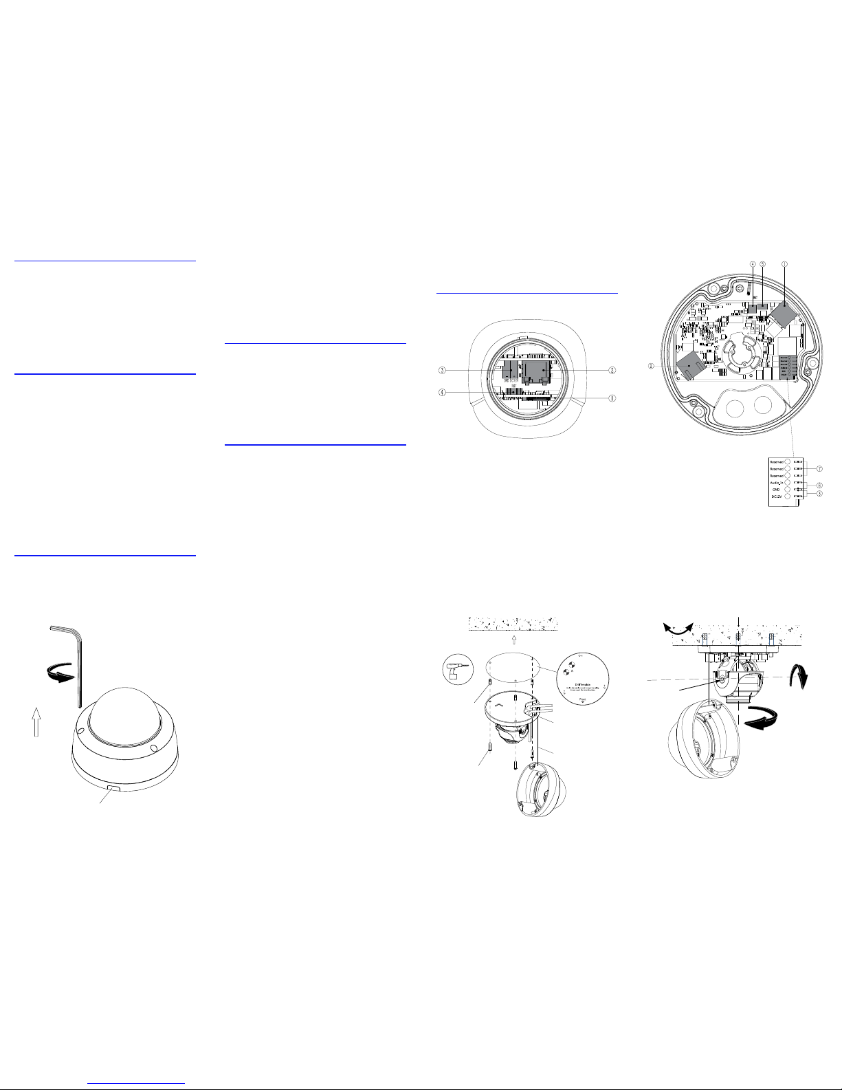
Anatomy of the Cameras
(1) Micro SD slot
(2) Ethernet port
(3) 12V power
(4) Reset button (hold for 5 seconds to reset)
(5) Microphone in
(6) Audio in
(7) Not for installer use
Installing the Dome
Loosen (do not remove) the screws in the dome
and open the camera. CAUTION: Do not throw
away the foam ring around the camera lens! It
prevents glare from the camera’s infrared lights.
Using the adhesive template, drill 4.5mm holes
for the wall anchors (marked B on the template).
If needed, drill holes for the cables (marked A on
the template).
If the cabling will run along the wall, use a
Phillips screwdriver to detach and remove the
cable access (see below le).
In addition, before you terminate the cables,
you must push the cable through the rubber
blisters that plug the cable access holes. Do not use
a tool to puncture the blisters; if you just push the
category cable through, it will create a watertight
seal.
Insert the wall anchors, then place the camera
base in place and secure with screws.
Connect the network cable. If needed, connect
the power and audio cabling. Note that the power
and audio share the same ground.
Remove the shroud around the camera and
loosen the set screw. Aim the camera as desired,
and tighten the set screw. Place the desiccant pack
inside the camera where it won’t interfere with the
view, and replace the shroud.
Secure the dome cover to the camera, Remove
the protective covering from the dome.
level 0°–330°
set
screw
rotate 0°–350°
angle 0°–75°
cable
access
wall
anchor
lanyard
camera
cabling
screw
 Loading...