

VisualGate SVP-1000 Full Manual
Network Video Decoder SVP-1000 Full Manual
1
NETWORK VIDEO DECODER
MODEL: SVP-1000
Full Manual (English)
Version 1.0
Network Video Decoder SVP-1000 Full Manual
2
Warning
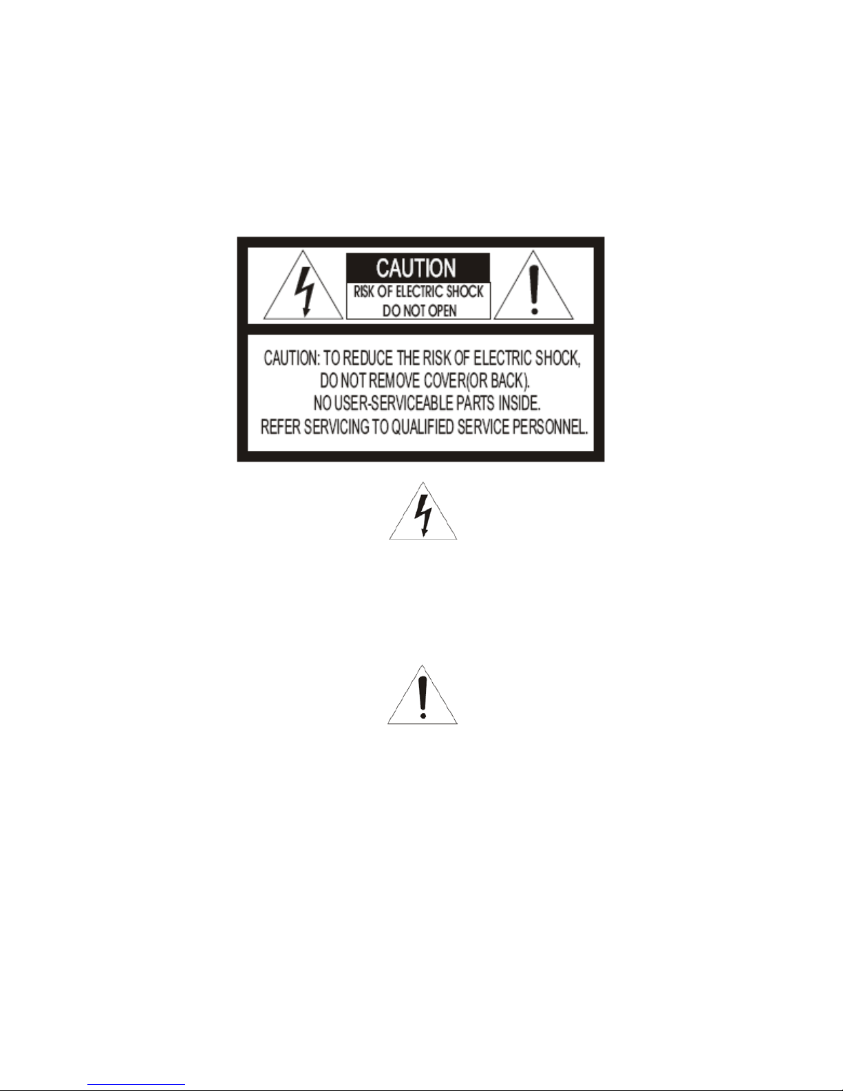
The lightning flash with arrowhead symbol, within an equilateral triangle, is intended to
alert the user to the presence of uninsulated "dangerous voltage" within the product's
enclosure that may be of sufficient magnitude to constitute a risk of electric shock to
persons.
The exclamation point within an equilateral triangle is intended to alert the user to the
presence of important operating and maintenance (servicing) instructions in the
literature accompanying the product.
Network Video Decoder SVP-1000 Full Manual
3
Warning
This equipment has been tested and found to comp ly with the limits for a Class B Digital Device,
pursuant to Part 15 of the FCC Rules. These limits are designed to provide reasonable protection
against harmful interference in a residential installation. This equipment can radiate rad io frequency
energy therefore, if it is not installed and used in accordance with the instruction, it may cause
harmful interference to radio communication. However, there is no guarantee that interference will
not occur in a particular installation. If this equipment causes harmful interference to radio or
television reception, which can be determined by turning the equipment off and on, the user is
encouraged to try to correct the interference by one or more of the following measures:
- Reorient or relocate the receiving antenna.
- Increase the separation between the equipment and receiver
- Connect the equipment into an outlet on a circuit different from that to which the receiver is
connected.
- Consult the dealer or an experienced radio/TV technician for help.
Caution
Any changes or modifications in construction of this device which are not expressly approved by the
party responsible for compliance could void the user’s authority to operate the equipment.

Network Video Decoder SVP-1000 Full Manual
4
Precautions
1. HEED WARNINGS
Adhere to all warnings on the appliance and in the operating instructions.
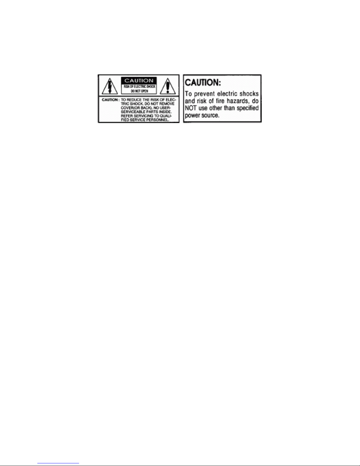
2. POWER SOURCES
Operate this equipment only from the type of power source indicated on the label. If you are not
sure of the type of power being used, consult your dealer or local power company.
3. OVERLOADING
Do not overload wall units and extension cords, as this can result in a risk of fire or electric shock.
Frayed power cords, damaged or cracked wire insulation, and broken plugs are dangerous.
Periodically examine the cord and replace it if appearance indicates damage or deteriorated
insulation.
4. POWER PLUG PROTECTION
Route the power supply cords so they cannot be walked on or pinched by items placed upon or
against them.
5. VENTILATION
Do not block the slots or openings of the video server and do not place the equipment on a bed,
soft rug, or other similar surface.
6. ATTACHMENTS
Do not use attachments other than those specifically recommended by the equipment
manufacturer as they may cause hazards.
7. TO PREVENT SHOCK HAZARD, DO NOT EXPOSE THIS UNIT TO RAIN OR
MOISTURE
If you spill liquid on the unit, consult authorized service personnel. Moisture can damage internal
parts. Do not use this equipment near sources of water.
8. ACCESSORIES
Use only with a manufacturer recommended card, stand, tripod, bracket or table. The equipment
may fall, causing serious injury to a child or adult and serious damage to the appliance.
9. CLEANING THE OUTSIDE SURFACES
Unplug this equipment from the wall outlet before cleaning. Use a damp cloth for cleaning.
10. REQUIRING SERVICE
Unplug the equipment from the wall outlet and request qualified service personnel.
11. SAFETY CHECK
Upon completion of any service or repairs to this equipment, ask the service technician to
perform safety checks to determine that the equipment is in safe operating condition.

Network Video Decoder SVP-1000 Full Manual
5
12. IMPORTANT NOTE TO THE INSTALLER
This installation should be made by a qualified service person and should conform to all local
codes. In order to provide this product with protection against risk of un intentional operation by
employees, customers, janitors and cleaners working on the premises, and from falling objects,
building vibrations and similar causes, it is recommended this product be enclosed in the tamperresistant lock box. Make sure that the lock box is well ventilated or maintained with an air cooling
system.

Network Video Decoder SVP-1000 Full Manual
6
Table of Contents
1. Introduction of SVP-1000................................................................................................7
1.1. Product Overview................................................................................................7
1.2. Features...................................................................... ... ................................... ........7
1.3. Packing Contents .................................................................................................8
1.4. System Requirements..........................................................................................8
1.5. System Configuration..........................................................................................9
1.6. Physical Description...........................................................................................10
1.6.1. Front View...................................................................................................10
2. Basic Setup of SVP-1000................................................................................................12
2.1. Installation.................................................................................................... .........12
2.2. Network Setting of a PC.............................. ................................ ... ......................13
2.2.1. Verifying the network setup status of a user PC......................................13
2.2.2. Operation of the Web Viewer (URL 192.168.1.10)...................................16
3. Configuration of Network Environment......................................................................19
3.1. Check up Network Environment and Installation Type...................................19
3.2. Installation.................................................................................................... .........20
3.2.1. IP Address Setup..........................................................................................20
4. Display Mode ................................................. ................................... ..............................23
4.1. Initial Login Screen...............................................................................................23
4.1.1. Installation of the Web Viewer..................................................................23
4.1.2. Initial Log-in Screen of SVP-1000.............................................................24
4.2. SVP-1000 Setting Page.........................................................................................25
5. Admin Setting Mode.......................................................................................................26
5.1. General Setting..................................................... ................................... .. ............26
5.2. Registration Setting................................................................ ..... ... ..... ..... ... ..... ....27
5.3. Language Setting............................. ..... ... ..... ... ..... ..... ... ..... ... ..... ...... .. ...... .. ...... ..... .28
5.4. Information Setting.............................................................. ... ..............................29
5.5. Network Setting............................... .. ...... .. ...... ..... ... ..... ..... ... ..... ... ..... ...... .. ...... .. ....31
APPENDIX A. Video Server Connection Diagram........................................... ..............33
APPENDIX B. Troubleshooting....................... ..... ... ..... ...... .. ...... .. ...... ..... ... ..... ..... ... ..... ... .35
APPENDIX C. Technical Specification of SVP-1000........................................ ..............36

Network Video Decoder SVP-1000 Full Manual
7
1. Introduction of SVP-1000
1.1. Product Overview
• About the Video DECODER
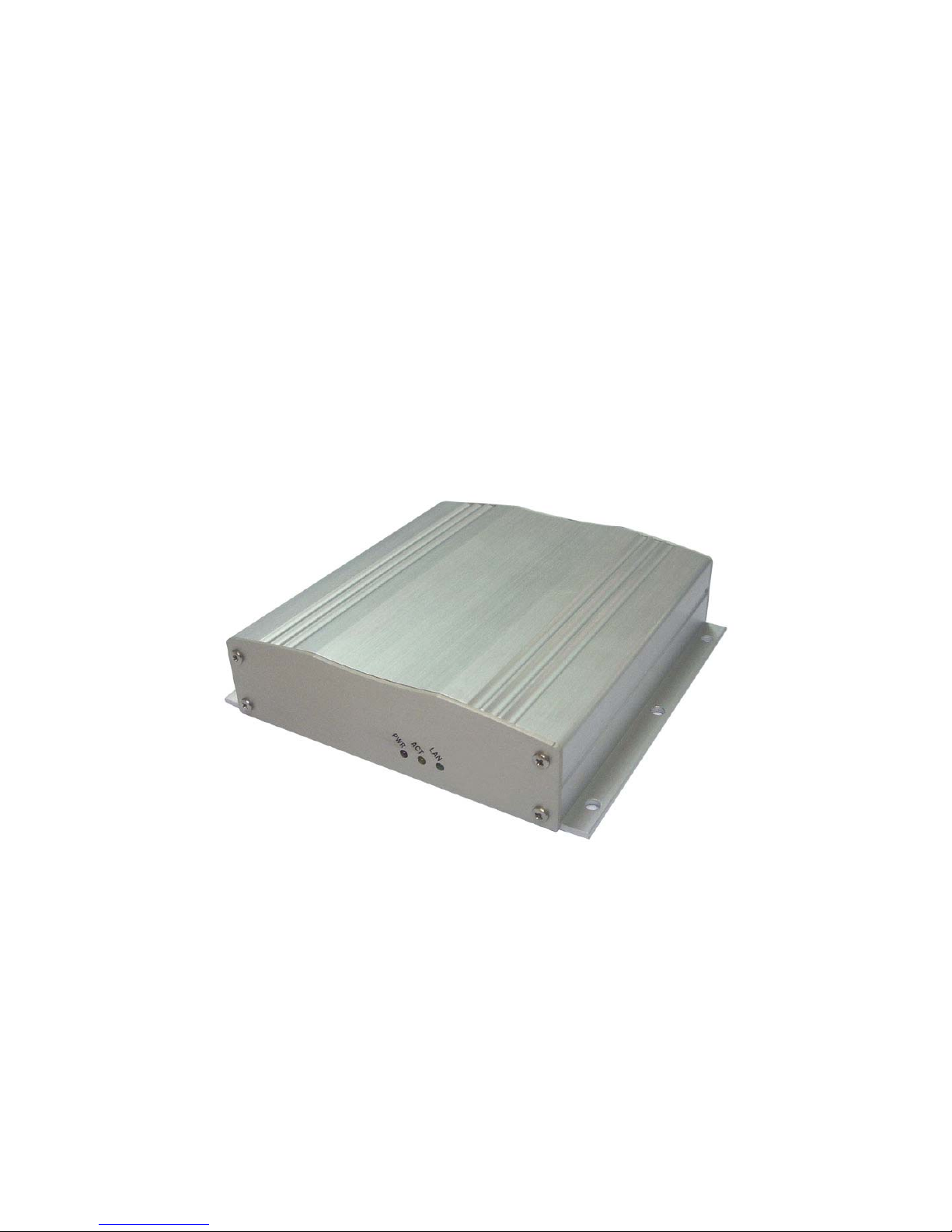
SVP-1000, the NETWORK VIDEO DECODER is equipped with an embedded system for displ a ying
MPEG-4 video streams arriving from the Internet. Without requiring a PC, NETWORK VIDEO
DECODER (SVP-1000) can log in to the remote Video Server / camera located an ywhere in the
world. In some applications the footprint and expe nse of a PC is impractical to decode the network
video streams. In these cases, the embedded NETWORK VIDEO DECODER (SVP-1000) is a
much more efficient and cost effective solution. Video output of SVP-1000 is connected to a TV or a
monitor directly.
1.2. Features
Compact Size
Embedded Linux
Receive Live& Real time Video streams
MPEG-4 Decompression
Low Latency
Built-in Watch-Dog Timer
Built-in WEB Decoder
Support Full Duplex Audio
No need Personal Computer
Support Composite Video
Support all VisualGate Products
Network Video Decoder SVP-1000 Full Manual
8
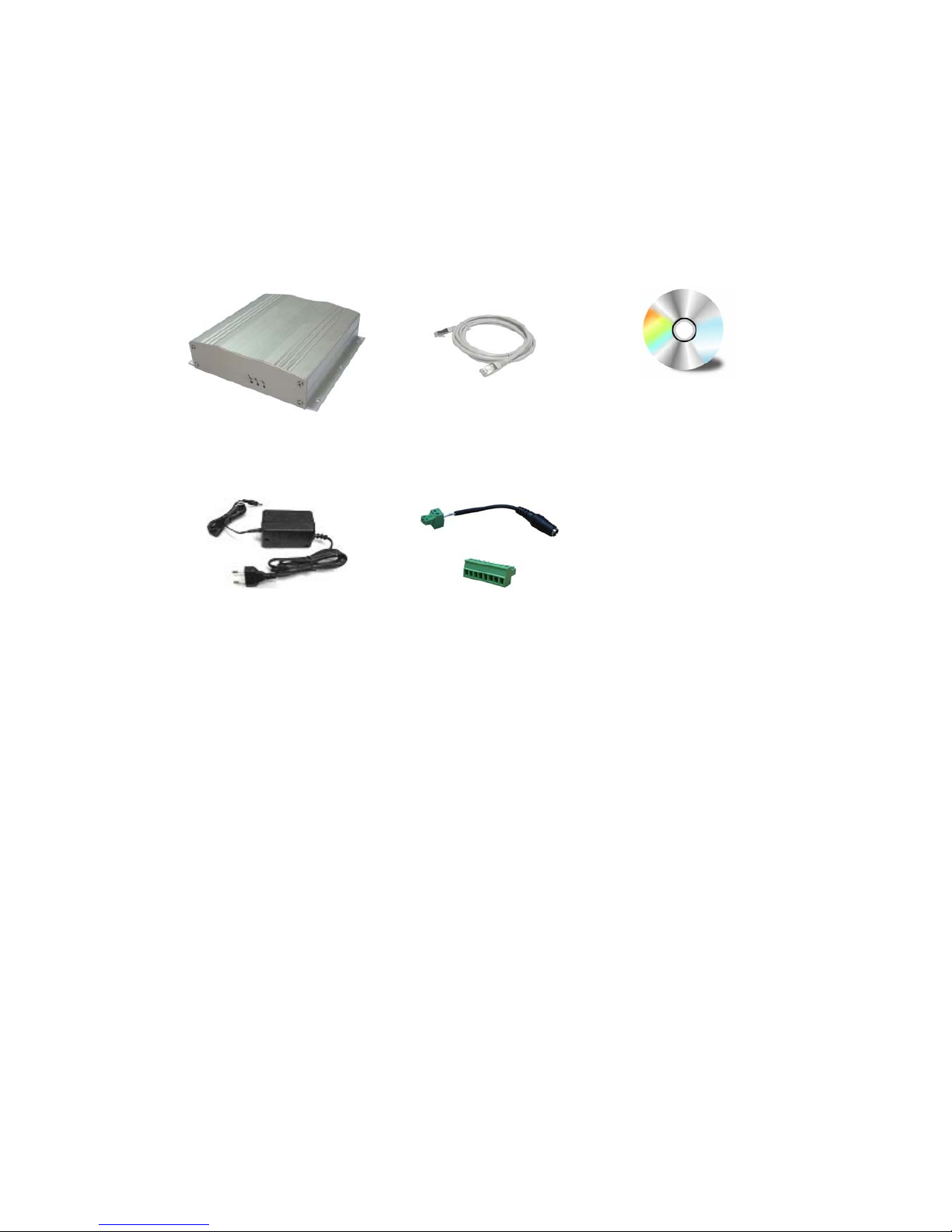
1.3. Packing Contents
NETWORK VIDEO DECODER Cross LAN Cable CD-ROM with manual and
software
DC Adapter(12V/1A)
* Separate Sale
Power Cable
+Terminal Block 2p
Terminal Block 5p
1.4. System Requirements
Operating System : Microsoft Windows® 2000 or Windows® XP
CPU : Intel® Pentium®Ⅳ1.6Ghz or faster
RAM : 512MB or higher
VGA : AGP, Video RAM 64MB or higher
Web Browser : Internet Explorer version 6.0 or higher
Direct-X : 8.x or higher
INPUT Voltage : DC 12V / 1A
Operating Temperature: : 0℃ ~ 50℃(32~122℉)
Humidity: 20~80% RHG, Non-Condensing
Network Video Decoder SVP-1000 Full Manual
9
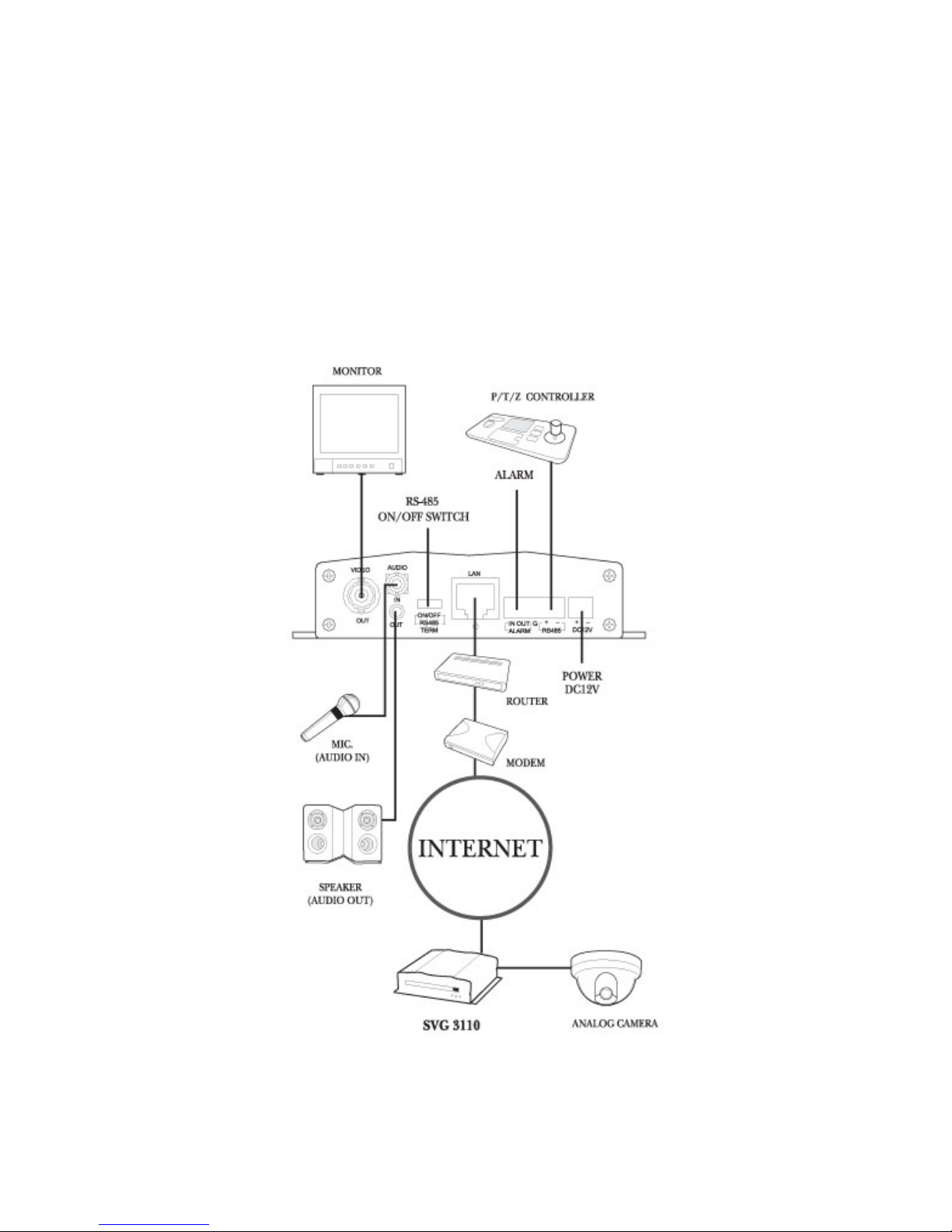
1.5. System Configuration
Network Video Decoder SVP-1000 Full Manual
10
1.6. Physical Description
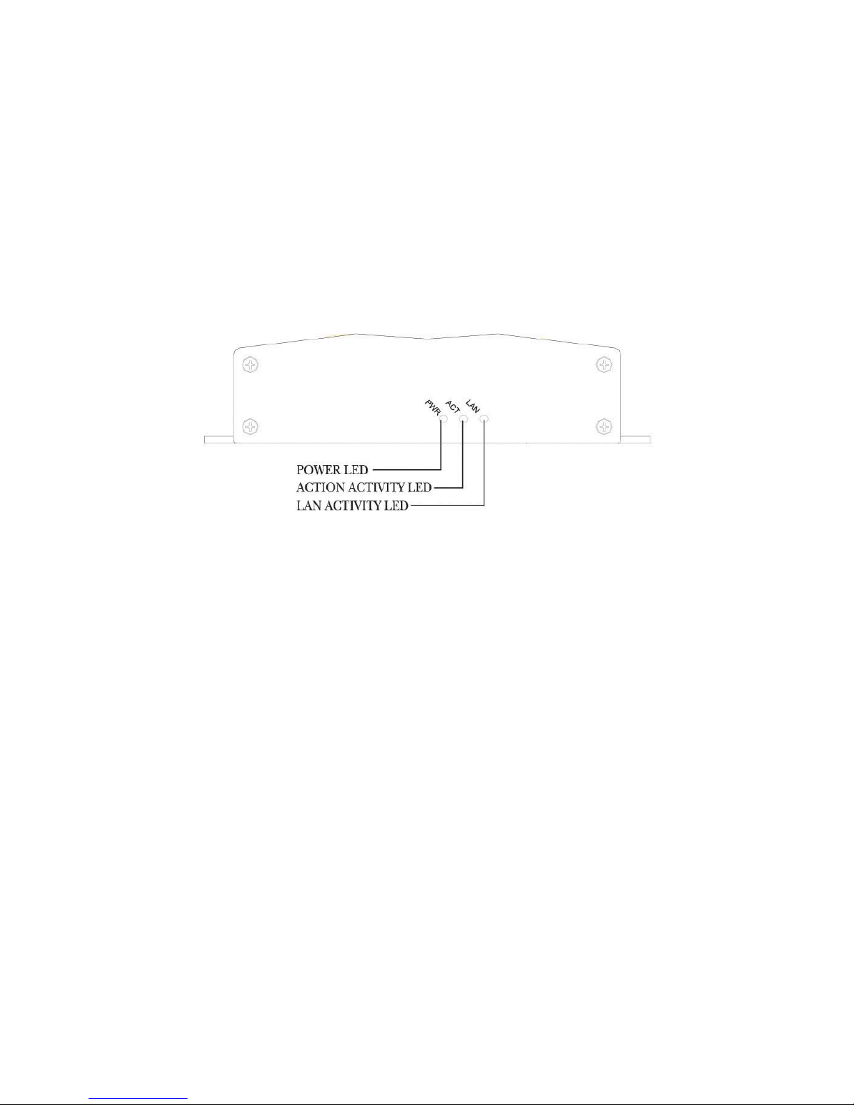
1.6.1. Front View
1) POWER : Power Supply status displays (Red LED on)
2) LAN: When data is transmitted and received through the LAN port, the LED blinks.
3) OPER: 1Channel Video Server is in operation (Orange LED blinks)
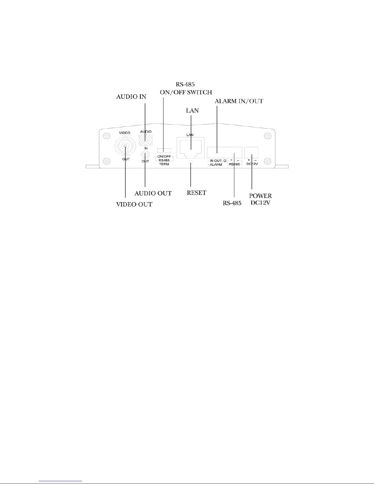
1.6.2. Rear View
Network Video Decoder SVP-1000 Full Manual
11
1) VIDEO OUT : 1Vp-p Composite, 1Channel
2) AUDIO IN : MONO Audio Input, 1Channel
3) AUDIO OUT : MONO Audio Output, 1Channel
4) POWER : DC12V /1A
5) ALARM IN/OUT : Port for alarm input, output
6) RS-485 : Port for P/T/Z control.
7) LAN : RJ-45 Ethernet Connector
8) RESET : Initial state which is factory default
9) RS-485 ON/OFF : RS-485 On/Off switch
10) ALARM IN/OUT : TTL LEVEL input/output
 Loading...