

Page 1
ASSEMBLY INSTRUCTIONS
DRY
Davis Sconce
Item # SL2923
WE RECOMMEN D IN STALLATION OF THIS LIGHTING FIXTURE BE DON E BY A
LICENSED E LECTRICIAN.
WARNING *** SWITCH OFF THE MAIN E LECTRICAL SUPPLY FROM TH E MAIN
FUSE BOX/CIRCUIT BR EAKER BEFORE INSTALLATION.
INS PECT ITEM CARE FULLY BEFORE ATTEMPTING TO INS TALL. IF TH ERE IS
ANY DAMAGE OR OBVIOUS DE FECT, DO NOT INSTALL.
ITEM MAY NOT BE RETU RNED ONCE IT HAS BEEN INS TALLED.
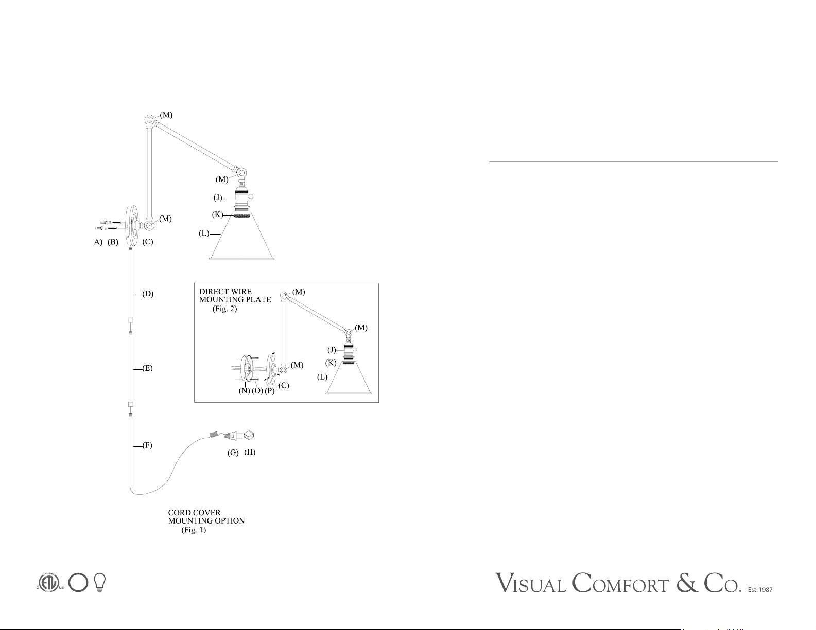
1. CORD COVER ASSEMBLY (See Fig. 1)
1. Remove all parts carefully from the box. Screw threaded nipple of cord cover
(D) into bottom threaded opening of back plate (C).
2. Thread cord cover (E) into cord cover (D), thread cord cover (F) to cord cover
(E) and hand tighten.
3. Measure center points between both mounting holes at back of fixture
base (C). Mark two points with same distance on the wall, make sure they are
vertical with each other.
4. Drill small holes at both points, hole should be big enough to accommodate
with plastic anchors (A). Install plastic anchors (A) into the holes in the wall.
5. Insert mounting screws (B) into plastic anchors (A), make sure screw head
1/8” threads are visible. Hook fixture base (C) onto both screws (B). Place
shade (L) onto the top of socket (J) and tighten with socket ring (K).
6. Insert light bulb into socket. Remove plastic cover (H) from plug (G). Plug
lamp into wall outlet.
ADJUSTMENT INSTRUCTIONS
1. Loosen adjustment keys (M) found on the swivel.
2. Adjust lamp arm and socket to desired position.
3. Tighten the adjustment keys.
Page 2
ASSEMBLY INSTRUCTIONS
DRY
Boston Functional Double Arm Library Light
Item # SL2923
WE RECOMMEN D IN STALLATION OF THIS LIGHTING FIXTURE BE DONE BY A
LICENSED E LECTRICIAN.
WARNING *** SWITCH OFF THE MAIN E LECTRICAL SUPPLY FROM THE MAIN
FUSE BOX/CIRCUIT BR EAKER BEFORE INSTALLATION.
INS PECT ITEM CARE FULLY BEFORE ATTEMPTI NG TO IN STALL. IF THERE I S
ANY DAMAGE OR OBVIOUS DE FECT, DO NOT INSTALL.
ITEM MAY NOT BE RETURN ED ONCE IT HAS BEE N IN STALLED.
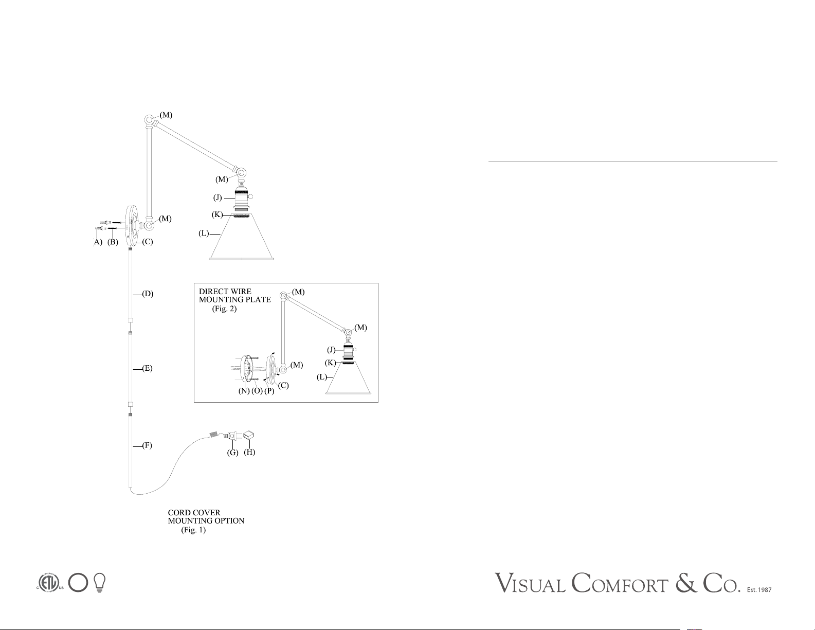
1. DIRECT WIRE INSTALLATION (See Fig. 2)
1. Follow step 1 of CORD COVER ASSEMBLY.
2. Guide wiring from wall outlet through center hole in mounting plate (N). Affix
mounting plate (N) to wall outlet box with mounting screws (0) provided.
3. Cut fixture cord twelve inches away from fixture base (C) and remove by
grasping plug (G) and pulling out of cord cover (D, E & F).
4. Connect the ground screw (green color) of the fixture to the bare copper
ground wire in the outlet box. The insulation on the fixture cord that was cut to
twelve inches in length in step 3 has a smooth side and a ribbed side. Connect
the smooth wire to the black wire in the outlet box (not shown in diagram).
Connect the ribbed wire to the white wire in the outlet box.
5. Attach fixture base (C) to the affixed mounting plate (N), and secure with
base screws (P).
6. Follow steps 7 & 8 and adjustment of CORD COVER ASSEMBLY.
 Loading...