

Page 1

H-DVP System
User Manual
Visual Circuits Corporation
Page 2

Trademarks
The Visual Circuits logo is a registered trademark in the United States
and other countries. All other products, services or compan y names
mentioned herein are claimed as trademarks and trade names by their
respective companies.
c Visual Circuits, 1999-2000. All rights reserved.
No porti on of this manual ma y be copied by any means without the pri or
consent of Visual Circuits.
Visual Circuits
5155 East River Road, Suite 401
Minneapolis, MN 55421
http://www.visualcircuits.com
Visual Circuits Publication Number: 813-0002a
Page 3

Federal Communications Radio Frequency Interference
Statement
WARNING: Changes or modifications to this unit not expressly
approved by the party responsible for compliance could void the user’s
authority to operate the equipment.
This equipment has been tested and found to comply with the limit s for a
Class A digi tal device, pur s uant to Part 15 of the FCC Rules. These
limits are designed to provide reasonable protection against harmful
interference when the equipment is operated in a commercial
environment. This equipment generates, uses, and can radiate radio
frequency energy and, if not installed and used in accordance with the
instructional manual, may cause harmful interference to radio
communications. Operation of this equipment in a residential area is
likely to cause harmful interference in which case the user will be
required to correct the interference at his own expense. However, if this
equipment does cause interference to radio or television equipment
reception, which can be determined by turning the equipment off and on,
the user is encouraged to try to correct the interference by one or more of
the following measures
❏ Reorient or relocate the receiving antenna.
❏ Increase the separation between equipment and receiver.
❏ Connect the equipment to an outlet on a circuit different
from that to which the receiver is connected.
❏ Consult the dealer or an experienced radio/television
technicia n for help.
Compliance with Part 15 of the FCC Rules and
Regulations
This H-DVP system complies with Part 15 of the FCC rules and
regulations. Operation is subject to the following two conditions:
❏ This device may not caus e harmful i nterference.
❏ This device m ust accept any interference that may cause
undesired operatio n.
Page 4
NOTE
Changes or modifications to this device not
expressly approved by the party responsible for
compliance could void the userºs authority to
operate the device.
Industry Canada
This Class A digital appartus meets all requirements of the Canadian
Interference-Caus ing Equi p ment Re gu lati on s.
Cet appareil numerique de la classe A respecte toutes les exigences du
Regulement sur le materiel brouilleur du Canada.
EMC and Safety Directive Compliance
The CE mark is affixed to this Visual Circuits Corporation product to
confirm compliance with the following European Community Directives:
Council Di rective 89/336/ EEC of 3 May 1989 on the approximation of
the laws of Member States relating to electromagnetic compatibility.
And
Council Directive 73/23/EEC of 19 Februa ry
1973 on th e harmonization of th e laws of
Member States relating to electrical equipment
designed for use within certain voltage limits:
Each ammended by
Council Directive 93/68/EEC of 22 July 1993
on the harmonization of CE marking
requirements.
Page 5
Safety and Regulatory Requirements
CAUTION
The DVD and CD-ROM drives contain a laser
system and are ·Class 1 Laser Products¸
under a U.S. Department of Health and Human
Services (DHHS) Radiation Performance
standard, according to the Radiation Control
for Health and Safety Act of 1968.
Should a unit ever require maintenance,
contact an authorized repair location.
CAUTION
An incorrectly replaced battery can cause an
explosion.
A lithium battery on the product provides
backup power for the timekeeping
mechanism. Should the battery fail, contact
an authorized repair location.
WARNING
An improperly grounded power supply can
result in electrical shock.
The AC power cord provided with your system
has a grounded plug. Always use a grounded
power cord with a properly grounded wall
outlet.
Page 6
CAUTION
Static electricity can harm delicate
components inside your server.
Discharge static electricity from your body
before you touch any of your computerºs
electronic components.
Page 7

CONTENTS
Overview . . . . . . . . . . . . . . . . . . . . . . . . . . . . . . 1
Specifications . . . . . . . . . . . . . . . . . . . . . . . . . . . . . . . .1
Installing the H-DVP System . . . . . . . . . . . . . . . . 3
Choosing an Appropriate Installation Location . . . . . .3
Installing the H-DVP System to a Rack . . . . . . . . . . . .4
Connecting Server Peripherals . . . . . . . . . . . . . . . . . . .4
Connecting Output and Power Cables . . . . . . . . . . . . .5
Connecting the Universal Cable . . . . . . . . . . . . . . .7
Connecting the Rackmount Breakout Box . . . . . . .7
Using the HDServe Application . . . . . . . . . . . . . . 9
Testing the Installation . . . . . . . . . . . . . . . . . . . . . . . .10
Playing MPEG Files . . . . . . . . . . . . . . . . . . . . . . . . . .10
Loading Files. . . . . . . . . . . . . . . . . . . . . . . . . . . . .11
Playing Files . . . . . . . . . . . . . . . . . . . . . . . . . . . . .11
Using Cross-Channel Synchronization . . . . . . . . . . . .11
Controlling Playback. . . . . . . . . . . . . . . . . . . . . . . . . .13
Setting the Program ID . . . . . . . . . . . . . . . . . . . . . . . .13
Using the HDCom Application . . . . . . . . . . . . . . 15
Setting Up a Serial Controller. . . . . . . . . . . . . . . . . . .15
Serial Command Reference. . . . . . . . . . . . . . . . . . . . .16
Callbacks . . . . . . . . . . . . . . . . . . . . . . . . . . . . . . . .16
Playback Commands. . . . . . . . . . . . . . . . . . . . . . .18
Cross-Channel Synchronization Commands. . . . .29
i
Page 8

Contents
Informational Commands . . . . . . . . . . . . . . . . . . .32
Registry Editing . . . . . . . . . . . . . . . . . . . . . . . . 37
Configuring the Driver . . . . . . . . . . . . . . . . . . . . . . . .37
Common Parameters. . . . . . . . . . . . . . . . . . . . . . . . . .37
Troubleshooting . . . . . . . . . . . . . . . . . . . . . . . . 41
Frequently Asked Questions . . . . . . . . . . . . . . . . . . . .41
Contacting Visual Circuits Corporation . . . . . . . 45
Contacting Technical Support. . . . . . . . . . . . . . . . . . .45
Information for Value Added Resellers or
Distributors. . . . . . . . . . . . . . . . . . . . . . . . . .45
What You Should Have Ready When You Call . .45
What You Can Expect When You Call. . . . . . . . .45
Technical Support Contact Information . . . . . . . .46
Returning Materials to Visual Circuits Corporation
(VAR/Distributor) . . . . . . . . . . . . . . . . . . . . . . . . .46
Appendix . . . . . . . . . . . . . . . . . . . . . . . . . . . . . 49
HD Software Developers Kit . . . . . . . . . . . . . . . . . . .49
General API information. . . . . . . . . . . . . . . . . . . .49
File Playback Commands . . . . . . . . . . . . . . . . . . .50
Audio/Video Output Commands. . . . . . . . . . . . . .58
Synchronization Functions . . . . . . . . . . . . . . . . . .65
Callback Functions . . . . . . . . . . . . . . . . . . . . . . . .68
Information Commands. . . . . . . . . . . . . . . . . . . . .71
ii
Page 9

Contents
Index . . . . . . . . . . . . . . . . . . . . . . . . . . . . . . . . 75
iii
Page 10

Contents
iv
Page 11
OVERVIEW
The H-DVP system is a high-definition digital video server that
can drive retail visual merchandising applications, location-based
entertainment, or any other type of video application.
The H-DVP system can play MPEG 1 and MPEG 2 video and
audio transport stream files on up to 4 channels. Through crosschannel synchronization, the H-DVP syst em can synchronize the
playback of any number of channels, even when individual
channels are temporarily stopped.
The H-DVP system ca n acce pt RS-23 2 commands in ASCII format
from standard show system controllers via a communication
application called HDCom.
Specifications
Table 1 lists the specifications of the H-DVP system.
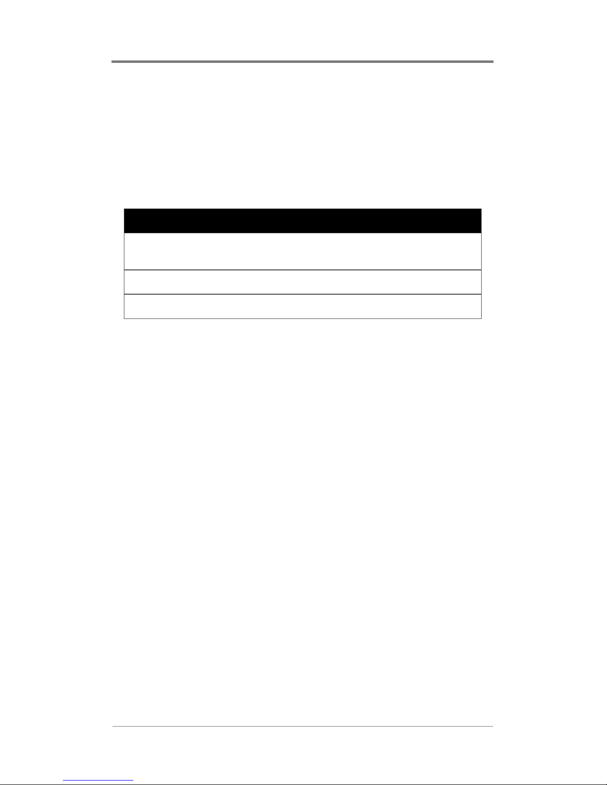
Table 1. H-DVP System Specifications
Chassis 3U 19″ (48 cm) rack mount
18″ D x 17″ W x 5.25″ H
(46 cm D x 43 cm W x 13 cm H)
Weight 38µ42 lb (17µ19 kg)
Power
requirements
90µ240 V, 80 W, aH, UL/CSA/T
Switchable for 110/220 V
üV/CE
1
Page 12

Overview
2
Page 13

INSTALLING THE H-DVP
SYSTEM
Installati on inv o lv es the fol lowing steps:
❏ Choosing an appropriate installation location
❏ Mounting the H-DVP system to a rack (optional)
❏ Connecting server peripherals
❏ Connecting output and power cables
❏ Testing the installation
Choosing an Appropriate
Installation Location
When choosing a location to install the H-DVP system, consider
the following requirements:
❏ The ambient temperature of the installation environment
must remain below 104 °F (40 °C). Keep in mind that the
operating temperature of a rack will be higher than room
temperature.
❏ Maintain a mi nimum ai rflow clearance of 1″ (2.5 cm) on all
sides of the H-DVP system.
❏ Ensure that the air intake of the H-DVP system does not
draw directly on the hot air exhaust from another unit.
❏ If installed on a rack, the rack must safely support the
combined weight of all de vic es mounted on the rack. Install
devices on a rack from the bottom up.
❏ The H-DVP system requires a minimum rack depth of 19″
(48.3 cm).
❏ In restricted areas, install only in accordance with Articles
100-16, 100-17, a nd 110- 18 of t he Nation al Ele ctri cal Cod e
ANSI/NFPA 70.
3
Page 14

Installing the H-DVP System
Installing the H-DVP System to a
Rack
The H-DVP system has side rails for installing into a rack. If you
use alternate rails for installing, consult the manufacturer of the
alternate rails to confirm that they meet the weight and stress
requirements to support the H-DVP chassis.
To mount the H-DVP system to a rack:
1. Position the H-DVP chassis in the lowest available slot on the
rack.
2. Verify that the rear panel of the H-DVP system is accessible.
3. Verify that all cables will reach their connectors on the rear
panel of the H-DVP system.
4. Tighten all fasteners for both front and rear mounting brackets
of the H-DVP system.
Connecting Server Peripherals
To easily use and configure the H-DVP system, connect a monitor,
keyboard, and mouse to the server. Ports for these peripherals are
clearly labeled on the rear panel of the server chassis.
Although peripherals such as a monitor and keyboard simplify the
use of the H-DVP system, you do not have to connect peripherals
to the serv er to monitor or adjust normal playback operation.
4
Page 15

Installing the H-DVP System
Connecting Output and Power
Cables
The H-DVP system is shipped with either a Universal Cable or a
Rackmount Breakout Box, both of which are terminated with a 25pin male D Sub connector. Each H-DVP channel corresponds to
one 25-pin female D Sub connector on the rear panel of the server
chassis. Therefore, one Universal Cable or Rackmount Breakout
Box will be necessary for each channel.
Table 2 on page 6 lists the pinouts of the 25-pin connectors.
5
Page 16
Installing the H-DVP System
Table 2. H-DVP Pinouts
Pin Output
1Ground
2µ4 None
5 Audio sub woofer
6µ7 None
8 Audio left rear
9 Vertical sync
10 None
11 Audio left front
12 Blue/Pb
13 Green/Y
14µ17 None
18 Audio center
19µ20 None
21 Audio right rear
22 None
23 Horizontal sync
24 Audio right front
25 Red/Pr
6
Page 17

Installing the H-DVP System
Connecting the Universal Cable
The Universal Cable terminates on the server side with a male D
Sub connector, and on th e output side with an 11-cabl e audio /video
breakout. The fi ve vi de o bre akout cables are shielded 75cables with female RCA connectors. The six audio breakou t cab les
are standard audio cables with female RCA connectors. Each
breakout cable is labeled.
To connect the Universal Cable:
1. Verify that the Universal Cable will not inadvertently come
into contact with other electrical devices or cables. Follow all
guidelines pr oscribed for electr ical de vices conn ected to—or in
close proximity to—the H-DVP server.
2. Completely back out the set screws on both sides of the
Universal Cable’s male D Sub connector.
Ω coaxial
3. Orient the Universal Cable’s male D Sub connector to the
appropriate female D Sub connector on the H-DVP server.
4. Connect the two D Sub connectors by applying gentle, even
pressure. Do not force the connectors together, and do not use
the set screws to “pull” the connectors together.
5. When the two D Sub connector s are fully connect ed, secure the
Universal Cable in place with the set screws.
6. Connect the break out ca ble s on the out put end of the Uni v ers al
Cable to the appropriate output devices.
Connecting the Rackmount Breakout Box
The Rackmount Breakout Box terminates on the server side with a
male D Sub connector and on the output side with a row of audio
and video breakout connectors. The video breakout connectors are
female BNC. The audio breakout connectors are terminal post
(“Phoenix” type) connectors. Each breakout connector is labeled.
To connect the Rackmount Breakout Box:
7
Page 18

Installing the H-DVP System
1. Verify that the Rackmount Breakout Box and the cables
connected to it will not inadvertently come into contact with
other electrical devices or cables. Follow all guidelines
proscribed for electrical devices connected to—or in close
proximity to—the H-DVP server.
2. Completely back out the setscrews on both sides of the
Rackmount Breakout Box’s male D Sub connector.
3. Orient the Rackmount Breakout Box’s male D Sub connector
to the appropriate female D Sub connector on the H-DVP
server.
4. Connect the two D Sub connectors by applying gentle, even
pressure. Do not force the connectors together, and do not use
the setscrews to “pull” the connectors together.
5. When the two D Sub connector s are fully connect ed, secure the
Rackmount Breakout Box’s connector in place with the
setscrews.
6. Connect output equipment to the breakout connectors on the
Rackmount Breakout Box.
8
Page 19
USING THE HDSERVE
APPLICATION
The HDServe application is a sample program that you can use as
a model for your own application, or to test your H-DVP system
installation. The H-DVP application calls most of the functions of
the application programming interface (API) documented in the HDVP software developer’s kit (SDK).
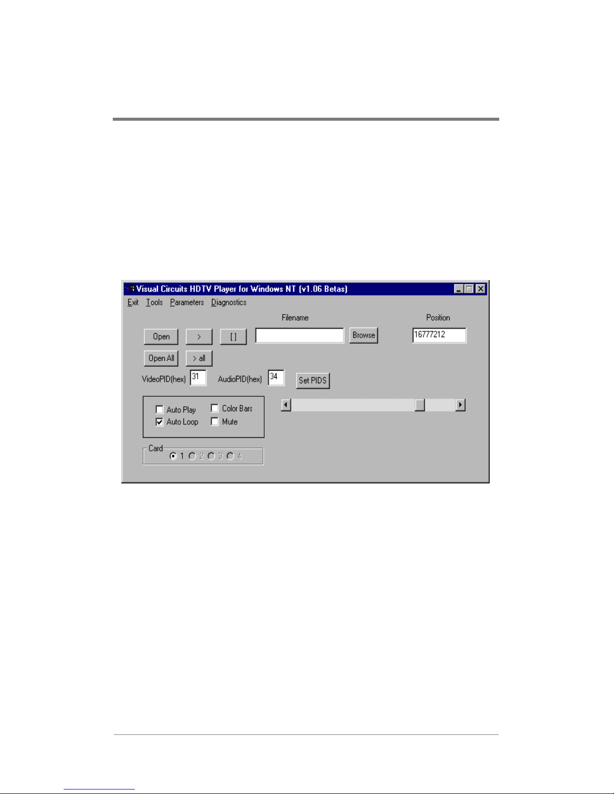
Figure 1 shows the main HDServe window and its components.
Figure 1. Main HDServe Window
9
Page 20

Using the HDServe Application
Testing the Installation
You should test the installation of the H-DVP system to verify that
you have set it up properly. Refer to Troubleshooting on page 41
for solutions to setup, installation, and testing problems.
To test the installation:
1. Start the HDServe application.
2. In the Card group (bottom left), click the number of a card to
which equipment has been connected.
3. Select the Color Bars checkbox.
4. If a test pattern appears on the appropriate monitor, then clear
the Color Bars checkbox and go to Step 6.
5. If a test pattern does NOT appear, then the monitor is not
hooked up correctly to the H-DVP server. Troubleshoot the
problem, then test the installation again.
6. Click Browse. Locate the /samples/mpeg directory, choose a
file, then click Open in the dialog box.
7. Click Open in the HDServe main window.
8. Click the play button .
9. If the file plays correctly, then the system is installed properly.
10. If the file does NOT play correctly, then the system may have
software or hardware problems. Refer to Troubleshooting on
page 41, or contact Visual Circuits according to the
instructions under Contacting Visual Circuits Corporation on
page 45.
Please refer to the following section for more detailed information
on using HD Serve .
Playing MPEG Files
Playing files in the HDServe application involves two stages:
❏ Loading files
❏ Playing files
10
Page 21
Using the HDServe Application
Loading Files
You can load one file on each channel. To load a file onto a
channel:
1. In the Card group, select a playback card.
2. Click Browse. Use the file browser to locate and select the fil e
you want to play.
3. Click Open.
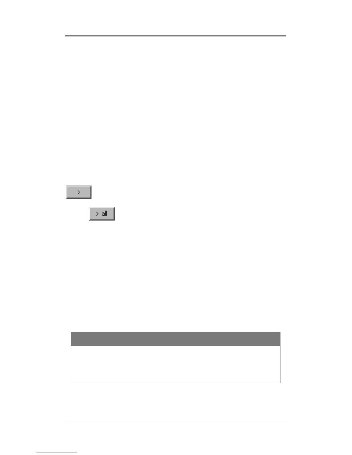
Playing Files
You can start playback on the current channel, or you can start
playback on all channels simultaneously.
To start playback on the current channel, click the play button
.
To start playback on all channels simultaneously, click the play all
button .
Using Cross-Channel
Synchronization
The H-DVP system has the ability to synchronize playback across
multiple channels (cro ss-cha nnel synchr onizat ion ). When ch annels
are synchronized, the H-DVP system will speed up or slow down
the playback of each channel to maintain identical playback
positions on every channel.
NOTE
All of the files that you want to synchronize should
have the same length and the same time stamp
information.
To use cross-channel synchronization:
11
Page 22

Using the HDServe Application
1. Load the desired MPEG file onto every channel.
2. On the Parameters menu, select Sync All Channels.
3. Click the play all button .
NOTE
The files may not be entirely synchronized until
after the first few seconds of playback.
12
Page 23
Using the HDServe Application
Controlling Playback
You can control the playback of a file by selecting some of the
checkboxes tha t appe ar in the HDServe mai n wi ndow. T abl e 3 lists
the playback features that are controlled by these checkboxes.
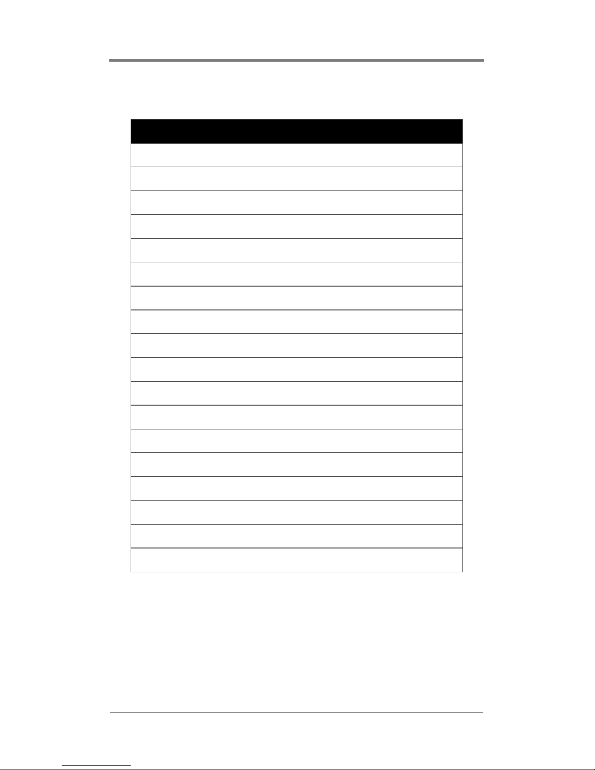
Table 3. Playback Control Checkboxes
Checkbox Behavior
Auto Loop Causes the current file to restart when
it reaches the end
Color Bars Turns on color bars
Mute Turns off audio
Setting the Program ID
You can manually set the audio and video program IDs (PIDs).
You should not need to set these values manually unless the HDVP system fails to automatically detect the correct PIDs.
To set the audio and video PIDs:
1. Type a hexidecimal PID value in the VideoPID box.
2. Type a hexidecimal PID value in the AudioPID box.
3. Click Set PIDS.
Set them each back to -1 to use the PIDS detected by the system.
13
Page 24

Using the HDServe Application
14
Page 25

USING THE HDCOM
APPLICATION
The HDCom application provides a way to send text commands
into the H-DVP server to load, play, and synchronize MPEG files.
You can set up a serial controller to send commands to the
HDCom application and direct the operation of the H-DVP server
remotely.
Setting Up a Serial Controller
A serial controller can exchange ASCII text messages with the
HDCom application. Before you can use a serial controller to
direct the H-DVP server, however, you must configure the
controller and the HDCom application to communicate using the
same settings. Consult the instructions for your serial controller for
information about modifying the controller’s communication
settings.
To modify the communication settings in the HDCom application:
1. Click the Settings menu.
2. Click the arrow in the Port box and select the appropriate
COM port from the list.
3. Click the arrow in the Baud Rate box and select a baud rate
from the list.
4. Click the arrow in the Data Bits box and select 7 or 8 from the
list.
5. Click the arrow in the Parity box and select Even or Odd from
the list.
6. Click the arrow in the Stop Bits box and select 0 or 1 from the
list.
7. In the Flow group, select the checkbox that matches the flow
control protocol used by the serial controller.
8. Click OK.
15
Page 26

Using the HDCom Application
Serial Command Reference
Using HDCom, you can send serial commands to the H-DVP
server, and you can receive callbacks from the server when certain
events are completed. Commands are in ASCII text and are
terminated with a decimal 13 character (carriage return).
Commands are not case sensitive.
NOTE
Card numbering starts at zero (i.e., the first card is
number 0, the second card is number 1). The
channel number is always 0.
Serial commands include:
❏ Callbacks
❏ Playback commands
❏ Cross-channel synchronization commands
❏ Informational comm ands
Callbacks
The server will issue callbacks whenever certain events occur.
Callbacks allow serial controllers to repond to server conditions.
Serial controllers are responsible for parsing callbacks and
reponding appropriately.
Callbacks are in the following format:
PHVVDJH.
❏ FDUG—The playback card
❏ FKDQQHO—The channel on the playback card
❏ PHVVDJH—A numerical message
&%FDUGFKDQQHO
The possible callback messages are listed in Table 4 on page 17.
16
Page 27
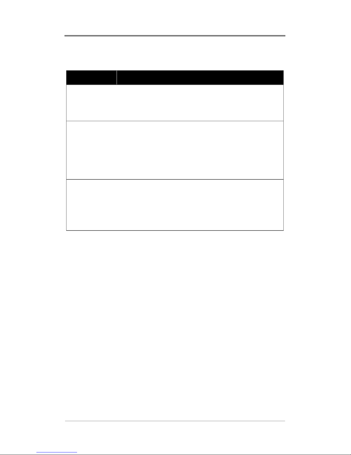
Table 4. Callback Messages
Message Meaning
1 File Read Complete
The server sends this callback when a
channel completes loading an MPEG file.
Playback of the file is not yet complete.
2 Playback Complete
The server issues this callback when a
channel finishes playing an MPEG file. This
callback will not be issued if the channel is in
auto-repeat mode, or if a new MPEG file has
already started loading in response to an
mpgLoadNext command.
5 File Read Start
The server issues this callback when a
channel begins loading a new MPEG file.
After this callback has been issued, an
mpgLoadNext command may be sent to the
channel.
Using the HDCom Application
17
Page 28

Using the HDCom Application
Playback Commands
mpgLoad
This command loads an MPEG file for playback on the specified
channel. This command does not play the file (see the mpgPlay
command on page 19).
Syntax
PSJ/RDGFDUGFKDQQHOILOHQDPH
Parameters
FDUG
The playback card
FKDQQHO
The channel on the playback card
ILOHQDPH
The full path and file na me of the MPE G file to load
Return Values
This command returns ACK if the file load was started
successfully, or NAK if the fi le could not be loaded (e.g., the file
was not found).
18
Page 29

Using the HDCom Application
mpgPlay
This command plays a previously loaded MPEG file on the
specified channel. The file must have already been loaded using
the mpgLoad command.
Syntax
PSJ3OD\FDUGFKDQQHO
Parameters
FDUG
The playback card
FKDQQHO
The channel on the playback card
Return Values
This command returns ACK if playback was started successfully,
or NAK if playback co uld not be started (e.g., no file previously
loaded).
mpgStop
This command stops playback of an MPEG file that is currently
playing on the specified chan nel.
Syntax
PSJ6WRSFDUGFKDQQHO
Parameters
FDUG
The playback card
FKDQQHO
The channel on the playback card
19
Page 30

Using the HDCom Application
Return Values
This command returns ACK if playback was stopped successfully,
or NAK if playback could not be stopped (e.g., no file currently
playing).
mpgLoadNext
This command loads an MPEG file on the specified card and
channel, and queue s the file so that it will play when the current
file finish es.
Syntax
PSJ/RDG1H[WFDUGFKDQQHOILOHQDPH
Parameters
FDUG
The playback card
FKDQQHO
The channel on the playback card
ILOHQDPH
The full path and file na me of the MPE G file to load
Return Values
This command returns ACK to indicate that the file was loaded
successfully, or NAK to indicate that the file could not be loaded
(e.g., the file was not found).
20
Page 31

Using the HDCom Application
mpgPlayAll
PSJ3OD\$OO
This command starts playback on all channels simultaneously. The
files for each channel to play must have been previously loaded
using the mpgLoad command.
Syntax
PSJ3OD\$OO
Parameters
None
Return Values
This command returns ACK to indicate that playback was started
successfully, or NAK to indicate th at pl ay back could not be start ed
on all channels.
mpgStopAll
This command stops playback on all channels simultaneously.
Syntax
PSJ6WRS$OO
Parameters
None
Return Values
This command returns ACK to indicate that all channels were
stopped successfully, or NAK to indicate that all channels could
not be stopped.
21
Page 32

Using the HDCom Application
mpgAutoRepeat
This command causes a channel to automatically loop its current
file. When the currently playing file is finished, the file is
automatically restarted from the beginning. The file continues to
loop until the mpgNoRepeat command is issued.
Syntax
PSJ$XWR5HSHDWFDUGFKDQQHO
Parameters
FDUG
The playback card
FKDQQHO
The channel on the playback card
Return Values
This command returns ACK if automatic loop function was turned
on, or NAK if the automatic loop function could not be turned on
(e.g., automatic loop was already on).
mpgNoRepeat
This command causes a channel to stop automatically looping its
current file.
Syntax
PSJ1R5HSHDWFDUGFKDQQHO
Parameters
FDUG
The playback card
FKDQQHO
The channel on the playback card
22
Page 33

Using the HDCom Application
Return Values
This command returns ACK if the automatic loop function was
turned off, or NAK if the automatic loop function could not be
turned of f (e.g., automatic loop was already off).
mpgClose
This command closes and unloads an MPEG file from the
specified channel.
Syntax
PSJ&ORVHFDUGFKDQQHO
Parameters
FDUG
The playback card
FKDQQHO
The channel on the playback card
Return Values
This command returns ACK if the file was closed successfully, or
NAK if the file could not be closed (e.g., the channel did not have
a currently loaded file).
23
Page 34

Using the HDCom Application
mpgSeek
This command sets the playback position of the currently loaded
file to the specified index.
Syntax
PSJ6HHNFDUGFKDQQHOSRVLWLRQ
Parameters
FDUG
The playback card
FKDQQHO
The channel on the playback card
SRVLWLRQ
The position in the current file where playback should begin
Return Values
This command returns ACK if the playback position was set
successfully, or NAK if the playback position could not be set
(e.g., no currently loaded file).
mpgMute
This command turns off the audio output of the specified channel.
The audio output can be turned on again using the mpgUnMute
command.
Syntax
PSJ0XWHFDUGFKDQQHO
Parameters
FDUG
The playback card
FKDQQHO
The channel on the playback card
24
Page 35

Using the HDCom Application
Return Values
This command returns ACK to indicate that audio output was
turned off, or NAK to indicate that audio output could not be
turned off (e.g., audio was already off).
mpgUnMute
This command restores audio output to a previously muted
channel.
Syntax
PSJ8Q0XWHFDUGFKDQQHO
Parameters
FDUG
The playback card
FKDQQHO
The channel on the playback card
Return Values
This command returns ACK if audio output was restored, or NAK
if audio output could not be restored (e.g., audio output was
already on).
25
Page 36

Using the HDCom Application
mpgSetAudioPID
This command sets the audio program ID to the value specified by
pid. Use this command to override the audio PID values detected
by the server software.
Syntax
PSJ6HW$XGLR3,'FDUGFKDQQHOSLG
Parameters
FDUG
The playback card
FKDQQHO
The channel on the playback card
SLG
The new value of the audio program ID
Return Value
This command returns ACK to indicate the audio program ID was
successfully changed, or NAK to indicate the audio program ID
could not be changed.
mpgSetVideoPID
This command sets the video program ID to the specified value.
Use this command to override t he video PID val ues dete cted by the
server software.
Syntax
PSJ6HW9LGHR3,'FDUGFKDQQHOSLG
26
Page 37

Using the HDCom Application
Parameters
FDUG
The playback card
FKDQQHO
The channel on the playback card
SLG
The new value of the video program ID
Return Values
This command returns ACK to indicate the video program ID was
successfully changed, or NAK to indicate the video program ID
could not be changed.
mpgColorBarOn
This command turns on color bars for the specified channel. You
can turn off color bars by using the mpgColorBarOff co mmand.
Syntax
PSJ&RORU%DU2QFDUGFKDQQHO
Parameters
FDUG
The playback card
FKDQQHO
The channel on the playback card
Return Values
This command returns ACK if color ba rs were successfully turned
on, or NAK if color bars could not be turned on.
27
Page 38

Using the HDCom Application
mpgColorBarOff
This command turns off color bars for the specified channel. You
can turn color bars on by using the mpgColorBarOn command.
Syntax
PSJ&RORU%DU2IIFDUGFKDQQHO
Parameters
FDUG
The playback card
FKDQQHO
The channel on the playback card
Return Values
This command returns ACK if color ba rs were successfully turned
off, or NAK if color bars could not be turned off.
28
Page 39

Using the HDCom Application
Cross-Channel Synchronization Commands
mpgSyncChannels
This command synchronizes a group of channels.
Syntax
PSJ6\QF&KDQQHOVJURXSPFDUGPFKDQQHOVFDUG
VFKDQQHO>«@
Parameters
JURXS
A group identifier from 0–32
PFDUG
The master playback card
PFKDQQHO
The channel on the master playback card (always zero)
VFDUG
The first slave card
VFKDQQHO
The channel on the first slave card (always zero)
Return Values
This command returns ACK if the synchronization group is
created successfu lly, or NAK if the group could not be created.
Remarks
The value supplied for the group parameter can be used by the
mpgUnSyncChannels, mpgPlaySyncChannels, and
mpgStopSyncChannels commands to control the entire
synchronized group. The group can be assigned any number from
0–32.
The scard1 and schannel1 parameters identify the first slave c ard
and channel. You can add an arbitrary number of slave channels
after the first, following the card-then-channel format. The channel
number for both master and slave cards is always zero.
29
Page 40

Using the HDCom Application
mpgUnSyncChannels
This command turns off synchronization for the specified group.
The group must previously have been set up using the
mpgSyncChannels command.
Syntax
PSJ8Q6\QF&KDQQHOVJURXS
Parameters
JURXS
The group identifier
Return Values
This command returns ACK if the group was unsynchronized
successfully, or NAK if the group could not be unsynchronized
(e.g., no such group).
mpgPlaySyncChannels
This command starts synchronized playback of all the channels in
the specified group. Playback of the group can be stopped using
the mpgStopSyncChannels command.
Syntax
PSJ3OD\6\QF&KDQQHOVJURXS
Parameters
JURXS
The group identifier
30
Page 41

Using the HDCom Application
Return Values
This command returns ACK if playback was started successfully,
or NAK if playback could not be started.
mpgStopSyncChannels
This command stops playback of all the channels in the specified
group.
Syntax
PSJ6WRS6\QF&KDQQHOVJURXS
Parameters
JURXS
The group identifier
Return Values
This command returns ACK if playback was stopped successfully,
or NAK if playback could not be stopped.
31
Page 42

Using the HDCom Application
Informational Commands
mpgDir
This command obtains the names of all the files and directories in
the specified path. The path may contain wildcards (e.g., *, ?). The
default value of the current directory is the default MPEG
directory.
Syntax
PSJ'LUSDWK
Parameters
SDWK
The path of a directory to list
Return Values
This command returns a list of all the files and directories in the
given directory, separated by a decimal 13 character (i.e., carriage
return).
mpgGetAllPositions
This command obtains the current file position for all channels.
Syntax
PSJ*HW$OO3RVLWLRQV
Parameters
None
32
Page 43

Using the HDCom Application
Return Values
This command returns the the letter P, followed by 16 file
positions.
Remarks
All of the return values are separated by spaces. The first file
position is for channel #0 on card #0; the second file position is for
channel #1 on card #0. The file positions of all 16 possible
channels are a lway s r etu rne d, regardless of how many channels are
actually in use.
mpgStatus
This command returns a list of v alues assoc iated with the specified
channel.
Syntax
PSJ6WDWXVFDUGFKDQQHO
Parameters
FDUG
The playback card
FKDQQHO
The channel on the playback card
Return Values
This command returns the letter S, followed by a space-delimited
list of status values.
33
Page 44

Using the HDCom Application
Remarks
Table 5 shows the values returned by this command, in the order
that they appear in the returned list.
Table 5. Values Returned by the mpgStatus Command
List
Position
1 Number of the card
2 Number of the channel on the card
3 Size of the currently loaded MPEG file, in
4 Current file position
Value
bytes
5 System file indicator
Æ A value of 0 indicates an independent
audio stream or an independent video
stream
Æ A value of 1 indicates an audio/video file
6 Horizontal size of the MPEG file, in pixels
7 Vertical size of the MPEG file, in pixels
8 n/a
9 Bit rate of the MPEG file, divided by 400
10µ14 n/a
34
Page 45

Using the HDCom Application
mpgCards
This command obtains the number of playback cards installed in
the serve r.
Syntax
PSJ&DUGV
Parameters
None
Return Values
This command returns the letter V, followed by a space, followed
by the number of cards installed in the server (1–4).
35
Page 46

Using the HDCom Application
36
Page 47

REGISTRY EDITING
Configuring the Driver
Windows NT has a registry editor, go to “start>>run>>regedit”:
Then:
HKEY_LOCAL_MACHINE\SYSTEM\CurrentControlSet\Service
s\VCCHD\Parameters
To change a DWORD value double click on it and modify as
required. The driver must always be stopped and restar ted before
changes will take effect. This can be done by accessing the
devices through “Control Panel>>Devices”, and stopping and
restarting the device. You may also simply reboot the system.
Remember to record your configura tion settings a s you make them.
Changing these settings can decrease system performance or cause
your operating system to lock up.
Common Parameters
The most commonly a djusted pa rameters ar e as follow (All values
are in hexadecimal):
bJitter = REG_DWORD 0x6400
This value, along with fJitter, help control the tolerance for A/V
sync.
BufferSizePerChannel = REG_DWORD 0x40000
Amount of system RAM allocated for EACH channel. Making this
buffer size small (even 128k) may result in glitches in the video
when the file syst em data delivery is uneven (depending on the
speed of your hard disk or network.) Must be an even multiple of
64k (0x10000).
37
Page 48

Registry Editing
component = REG_DWORD 0x0
1 for component video, 0 for RGB. (Can be overridden on a
channel by channel basis using the mpgSetVideoType function.)
DisableCCSync = REG_DWORD 0x0
1 to disable cross channel synchronization, 0 to enable (default 0.)
(Multi-channel servers only.)
DisableSync = REG_DWORD 0x0
1 to disable audio video synchronization (“lip sync”), 0 to enable
(default 0.)
fJitter = REG_DWORD 0x6400
This value, along with bJitter, help control the tolerance for A/V
sync.
freeTime = REG_DWORD 0x0350
This value, along with syncTime, controls the relative time
between periods in which the Vid eo Decoder chip is instructed to
perform an A/V sync. If a file gets out of sync over time, try
lowering this value. A value too low will hinder the performance
of playback, however.
LoopType = REG_DWORD 0x00
This value indicates the type of looping between files that the
driver will do. 0 indicates a “smooth” loop, in which the start of
the second file is started immediately after the first file. 1 indicates
a “slow” loop, in which the second file will wait for the first file to
end completely before starting. This results in a slight pause
between files, but may eliminate some jitter or pixelization that
may happen with the first type of looping. (Can be overridden on a
channel by channel basis using the mpgSetLoopType function.)
38
Page 49

Registry Editing
maxcards = REG_DWORD 0x8
A number 1 to 8 to i nit ialize less than the actual n umber of car ds in
the bus. (default 8)
maxdisks = REG_DWORD 0x1
Indicates the number or group of hard disks available from which
MPEG files will be read from.
MaxDMA = REG_DWORD 0x8000
Sets the maximum data delivery size from the system memory
buffer to the card. Adjusting this and MinDMA ca n tweak driver
performance.
maxfileread = REG_DWORD 0x200000
The maximum files read size. Used in conjunction with
minfileread.
MinDMA = REG_DWORD 0x1000
Sets the minimum data delivery size from the system memory
buffer to the card. Adjusting this and MinDMA ca n tweak driver
performance.
minfileread = REG_DWORD 0x100000
The minimum files read size. Used in conjunction with
minfileread. Setting the minimum higher reduced the amount of
seeking on the hard disk. If this value is too high, then too much
time is spent on an individual channel, which could cause
starvation in other channels.
multiapp = REG_DWORD 0x0
With this set to 0, only one application can link to HDAPI.DLL at
a time. With it set to 1, multiple applications can link, but
callbacks are disabled.
39
Page 50

Registry Editing
network = REG_DWORD 0x0
With this se t to 1, the dri ver can read files over the Windows NT
network. With it set to 0, it can not.
nocache = REG_DWORD 0x0
With this set to 0, normal NT file system caching is used. With it
set to 1, the cache is not grown when the files are played.
syncTime = REG_DWORD 0x1
This value, al ong with freeTime, controls the re lative time be twee n
periods in which the V ideo Decoder chip is instructed to perform
an A/V sync.
syncTolerance = REG_DWORD 0x4
This value controls the timing used in cross-channel
synchronization. See the FAQ section of the
40
Page 51

TROUBLESHOOTING
The frequently asked questions (FAQ) below can help you resolve
minor difficulties you may encounter when using the H-DVP
system. You can find additional support information on the Visual
Circuits Web site at www.visualcircuits.com. If your question is
not addressed i n thi s FAQ or on the Web s it e, you can co nta ct your
Visual Circuits Value Added Reseller (VAR) or Distributor for
support.
Frequently Asked Questions
Q. How do I play a file?
A. Before an MPEG file will play, it must be loaded. You can
issue the mpgLoad command through the HDCom appl ic at ion
to load a file. See Playing MPEG Files on page 10 for
instructions on using the HDServe application to play an
MPEG file.
Q. I played a file, but the H-DVP system didn’t display the video.
Why?
A. Your HD monitor is possibly not hooked up to the H-DVP
system correctly. Open the HDServe application and select the
Color Bar checkbox. Your HD monitor should display a color
bar test pattern. If a test pattern does not appear, your HD
monitor is not correctly hooked up to the H-DVP system. See
Connecting Output and Power Cables on page 5 for
instructions on hooking up audio and video output cables.
41
Page 52

Troubleshooting
Q. I get a test pattern on the screen, but my MPEG file still
doesn’t play correctly. Why?
A. The H-DVP software may be having trouble detecting the
audio and video program IDs in the MPEG file. If you know
the PIDs, you can set them manually with the
mpgSetAudioPID and mpgSetVideoPID serial commands in
the HDCom applicat ion. See Setting the Program ID on
page 13 for instructions on setting the PIDs in the HDServe
application.
Q. The lip sync feature is not working on my files. Why?
®
A. Several settings in the Windows NT
Registry can affect the
lip sync feature. Start the Regedit applet and set
HKEY_LOCAL_MACHINE\SYSTEM\
CurrentControlSet\Services\VCChd\Parameters\disablesy
nc to zero. Restart the VCCHD driver. If the lip sync feature
still does not work properly, try modifying
HKEY_LOCAL_MACHINE\SYSTEM\CurrentControlSet
\
Services\VCChd\Parameters\freeTime in increments of 50.
Each time you modify the freeTime entry, restart the VCCHD
driver.
Q. The cross-channel synchronization feature is not working on
my files. Why?
A. Cross-channel synchronization will not work unless all of the
channels are playing. Furthermore, all of the files that are
playing must be the same size and have the same time stamp.
If you are using a serial controller, you must issue the
mpgSyncChannels command to create a synchronization
group, and you must issue the mpgPlayAll command to play
the synchronized group.
42
Page 53

Troubleshooting
Q. All my files are set up correctly for cross-channel
synchronization, but they are still not synchronizing. Why?
A. Two settings in the W ind ows NT Regi st ry affect cross-c hannel
synchronization. Open the Regedit applet and set
HKEY_LOCAL_MACHINE\SYSTEM\
CurrentControlSet\Services\VCChd\Parameters\disableC
Csync to zero. Restart the VCCHD driver. If your fi le s ar e st ill
getting slightly out of sync with each other, you can modi fy
HKEY_LOCAL_MACHINE\SYSTEM\
CurrentControlSet\Services\VCChd\Parameters\syncToler
ance in increments of 1. Each time you modify the
syncTolerance entry, restart the VCCHD driver.
Q. How can I receive (and process) callback messages?
A. The HDCom application reports ASCII text callback messages
to a serial controller. It is up to the serial controller to receive,
parse, and use callback messages properly. See Callbacks on
page 16 for the format of callback messages reported by the
HDCom application.
Q. How can I set up a play list?
A. You can play one file after another seamlessly by issuing the
mpgLoadNext command through the HDCom application.
The HDCom applicatio n repor ts cal lback message 5 ( File Read
Start) whenever it is ready to receive an mpgLoadNext
command. You may wish to program a serial controller to
queue files from a list or a database—whenever the serial
controller receives callback message 5, it can read the next file
name from the list or database and send an mpgLoadNext
command.
43
Page 54

Troubleshooting
Q. How can I tell when a file has finished playi ng?
A. The HDCom application reports callback message 2 (Playback
Complete) to indicate when a file has finish ed playing.
However, this callback message will not be sent if the channel
is in automatic loop mode, or if the mpgLoadNext command
has been issued. In addition, the HDCom application may not
report this callback message until 1–2 se conds after the file has
actually finished playing.
Q. Sometimes files “block” or “pixelize” when looping back to
back. How can I correct this?
A. There are two ways that the driver can transition files when
looping. One way attempts a “smooth” transition, in which it
starts the beginning of the fil e immediately after detecting the
end of the file. This is the smoothest way of transitioni ng, but
can result in jittering or pixelization at the loop point. The
second wah of transitioning the file is that it waits for the file
to completely finish playback and come to a stop before
starting it again. This will cause a smal pause at the end of
athe file, but will eliminate jittering or pixelization at the loop
point.
You may select the transition type by changing the driver
parameter Loop Type. Setting it to 0 (zero) will produce the
first type of looping, setting it to 1 will produce the second.
(See section on changing driver parameters..........)
44
Page 55

CONTACTING VISUAL
CIRCUITS CORPORATION
Contacting Technical Support
Information for Value Added Resellers or
Distributors
If you are experiencing problems with the H-DVP system, consult
Troubleshooting on page 41 and the support information available
at www.visualcircuits.com first. If you need further assistance,
call Visual Circuits technical support at the telephone numbers
listed under Technical Support Contact Information on page 46.
What You Should Have Ready When You Call
Before you call Visual Circuits technical support, collect the
following pieces of informatio n:
❏ The serial number of the H-DVP unit
❏ The date of purchase of the unit
❏ The name of the distr ibutor or sales represen tative who sold
the unit
❏ A complete description of the installation or project details
on displays and other devices used.
❏ A complete description of the problem
What You Can Expect When You Call
Your call to Visual Circuits technical support will be handled in
the following manner:
1. A technical suppor t repr esent ati ve will record sev eral pi eces of
information (see What Y ou Should Have Ready When You Call,
above).
2. The representative will attempt to resolve your problem.
45
Page 56

Contacting Visual Circuits Corporation
3. If your problem is too complex to be resolved during your
initial conversation, the represe ntative will arran ge for you to
be called back at a la ter time. You will receive an in quiry
number that you can use to refer to your problem in the future.
NOTE
After regular business hours, the technical support
representative will always attempt to resolve your
problem and arrange for you to be called back the
next business day.
Technical Support Contact Information
The e-mail address for Visual Circuits technical support is:
❏ techsupport@visualcircuits.com
The telephone numbers for Visual Circuits technical support are:
❏ In the United States, 1-800-250-5533
❏ Outside of the United States, 763-571-7588
Returning Materials to Visual
Circuits Corporation
(VAR/Distributor)
If the H-DVP system has problems that cannot be corrected over
the telephone by Visual Circuits technical support, you may need
to return t he H-DVP server to Visual Circuits C orporation. All
materials shipped back to Visual Circuits Corporation must be
accompanied by a Ret urn Materials Authorization (RMA) number.
A Visual Circuits technical support representative will provide you
with an RMA number. Write the RMA number clearly on the
shipping label, as shown in Figure 2.
46
Page 57

Contacting Visual Circuits Corporation
Figure 2. RMA Format on Shipping Label
47
Page 58

Contacting Visual Circuits Corporation
48
Page 59

APPENDIX
HD Software Developers Kit
General API information
This document is meant as a resource for information on how to
use the functions included in the API for the HD Focus players.
Each function has been grouped with other functions of similar
usage into a group, allowing you to find related functions quickly.
Also included is a FAQ (Frequently Asked Question) section that
will attempt to di scuss some problems that arise frequently.
When a function is listed, the proper syntax for both Visual C++
and Visual Basic is displayed. In most cases the syntax will be
nearly exactly the same, except when arrays are passed, in which
the VB call will be somewhat different, because of differences
between VC and VB in how arrays are passed.
NOTE
It is also important to note that the card number
and channel number, which are sent as arguments
to many of the API functions, are ZERO based,
meaning that the first channel/card is referenced
using the number '0', the second channel/card is
referenced using the number '1', and so on.
For the HDTV drivers, all cards have only one channel on them.
Many of the functions below require both a card AND a channel.
In these cases, the channel number will always be zero. This
argument was kept in these calls to make the API compatible with
the API for our other p roducts, which will make it easier to port
any applications over.
49
Page 60

Appendix
The function definitions include the name of the function, and the
arguments that the function must be sent, as well as the variable
type of those arguments.
For VB programmers, the function must be DECLARED in a
module before it can be used.
All functions will return a no_error message, unless otherwise
stated.
File Playback Commands
mpgOpenDriver
The mpgOpenDriver func tion initi aliz es th e dr iver and pr epares the
card for use. This function must be called, successfully, before any
other functions will work.
9&&&$//PSJ2SHQ'ULYHU
Visual Basic Call
PSJ2SHQ'ULYHU
Remarks
It is absolutely impe rative that t his function is called e arly in the
program. The driver needs to be opened and initialized before any
other functions listed in the document will work.
mpgCloseDriver
The mpgCloseDriver function is used to let the driver go free for
use by the program, or other programs, later. This function should
be called while the program is closing.
50
Page 61

Appendix
9&&&$//PSJ&ORVH'ULYHU
Visual Basic Call
PSJ&ORVH'ULYHU
mpgLoad
The mpgLoad function opens an MPEG file and prepares it for
playback. If an MPEG is currently playing on the specified
channel, playback will be interrupted.
9&&&$//PSJ/RDG
LQW&DUG1XP
LQW&KDQ1XP
FKDU)LOH1DPH
Parameters
CardNum
0 based index of the card in the system.
ChanNum
0 based index of the channel on the card.
FileName
The full DOS path to the MPEG file.
Return Values
If the function succeeds, the return value is no_error . If the
requested MPEG file is not foun d, the function returns
file_not_found.
51
Page 62

Appendix
Visual Basic Call
PSJ/RDGORQJ&DUG1XPORQJ&KDQ1XPVWULQJ
)LOH1DPH
Remarks
A delay should be introduced between the call to mpgLoad and
mpgPlay in order to all ow the driver memory buffers to be filled
from the hard drive. This delay depends on the number of channels
playing and the speed of the hard drive. If the file is played to
quickly, starvation artifacts may result.
The InitOnOpen driver parameter effects the behavior of the
mpgLoad function. If initonopen is set to 0, the last frame of the
previous file played will remain on the output. If initonopen is 1,
the video out will go black and video sync will be lost. If
initonopen=2 the output will go black but video sync will not be
lost (4ReelTime RGB with RT daughterboard only.)
This function also will detect the audio and video PIDs used by the
file, as well as the audio type. If you would like to overwrite the
PIDs set automatically, you must use the mpgSetAudioPID or
mpgSetVideoPID functions.
mpgSetInitOnOpen
The mpgSetInitOnOpenl function allows the user to control some
behavior of the driver when a new file is loaded.
9&&&$//PSJ6HW,QLW2SHQ
':25'YDO
Parameters
Val
1 to set initialization upon file loading.
0 to not set initialization upon file loading.
52
Page 63

Appendix
Visual Basic Call
PSJ6HW,QLW2SHQORQJYDO
Remarks
When the argument val is set to 1, then upon loading of an MPEG,
the video output goes black, buffers are all flushed, and channels
requiring cross channel synchr onization will start up “tighter.”
When the argument val is set to 0, then upon loading of an MPEG,
there is a seamless transition to new files but no output reset is
available. However, sometime with this setting, a “rolling” or
“flickering” in some monitors is eliminated.
Testing should be done with both settings to determine the desired
presentation resu lts.
mpgPlay
The mpgPlay function starts or resumes playback on a channel.
9&&&$//PSJ3OD\
LQW&DUG1XP
LQW&KDQ1XP
Parameters
CardNum
0 based index of the card in the system.
ChanNum
0 based index of the channel on the card.
Visual Basic Call
PSJ3OD\ORQJ&DUG1XPORQJ&KDQ1XP
Remarks
The MPEG must have been opened first with mpgLoad.
53
Page 64

Appendix
mpgStop
The mpgStop function pauses playback on a channel.
9&&&$//PSJ6WRS
LQW&DUG1XP
LQW&KDQ1XP
Parameters
CardNum
0 based index of the card in the system.
ChanNum
0 based index of the channel on the card.
Visual Basic Call
PSJ6WRSORQJ&DUG1XPORQJ&KDQ1XP
Remarks
The MPEG must be have been started with mpgPlay or
mpgPlayAll. After the MPEG has been paused, another call to
mpgPlay or mpgPlayAll will resume playback.
mpgPlayAll
The mpgPlayAll function starts or resumes playback on all
channels on all installed cards.
9&&&$//PSJ3OD\$OO
Visual Basic Call
PSJ3OD\$OO
mpgStopAll
The mpgStopAll function stops playback on all channels on all
installed cards.
54
Page 65

Appendix
9&&&$//PSJ6WRS$OO
Visual Basic Call
PSJ6WRS$OO
mpgLoadNext
The mpgLoadNext function will set the spec ified chann el to start
another file immediately when the current one reaches the end.
9&&&$//PSJ/RDG1H[W
LQW&DUG1XP
LQW&KDQ1XP
FKDU)LOH1DPH
Parameters
CardNum
0 based index of the card in the system.
ChanNum
0 based index of the channel on the card.
FileName
The full DOS path to the MPEG file.
Visual Basic Call
PSJ/RDG1H[WORQJ&DUG1XPORQJ&KDQ1XPVWULQJ
)LOH1DPH
Remarks
This function allows for a seamless transition when one MPEG
ends and another one begins. A good time to call it is right when
one file begins to play. The driver will send a
MPG_FILE_READ_START message back to the application,
which would be a good time to call mpgLoadNext.
55
Page 66

Appendix
mpgAutoRepeat
The mpgAutoRepeat function sets the specified channel to loop
playback to start of file when it reaches the end.
9&&&$//PSJ$XWR5HSHDW
LQW&DUG1XP
LQW&KDQ1XP
Parameters
CardNum
0 based index of the card in the system.
ChanNum
0 based index of the channel on the card.
56
Page 67

Appendix
Visual Basic Call
PSJ$XWR5HSHDWORQJ&DUG1XPORQJ&KDQ1XP
Remarks
The auto repeat functionality won’t be used on the current file as
long as another file has been set to play with the mpgLoadNext
functionality.
mpgNoRepeat
The mpgNoRepeat turns off the auto repeat functionality set by
mpgAutoRepeat.
9&&&$//PSJ1R5HSHDW
LQW&DUG1XP
LQW&KDQ1XP
Parameters
CardNum
0 based index of the card in the system.
ChanNum
0 based index of the channel on the card.
Visual Basic Call
mSJ1R5HSHDWORQJ&DUG1XPORQJ&KDQ1XP
mpgClose
The mpgClose function stops pl ayb ack and cl oses t he fil e handle of
the file loaded.
9&&&$//PSJ&ORVH
LQW&DUG1XP
LQW&KDQ1XP
57
Page 68

Appendix
Parameters
CardNum
0 based index of the card in the system.
ChanNum
0 based index of the channel on the card.
Visual Basic Call
PSJ&ORVHORQJ&DUG1XPORQJ&KDQ1XP
Audio/Video Output Commands
mpgSetVideoType
The mpgSetVideoType function overrides the default output video
type as set in the registry and allows RGB or component output on
a channel by channel basis.
9&&&$//PSJ6HW9LGHR7\SH
LQW&DUG1XP
LQW&KDQ1XP
FKDU9LG7\SH
Parameters
VidType
0 – sets video for the selected channel to RGB output.
1 – sets video for the selected channel to component
output .
58
Page 69

Appendix
Visual Basic Call
PSJ6HW$96\QFORQJ&DUG1XPORQJ&KDQ1XPE\WH
9LG7\SH
mpgSetLoopType
The mpgSetLoopType function overrides the default looping type
as set in the registry.
&&&$//PSJ6HW9LGHR7\SH
V
LQW&DUG1XP
LQW&KDQ1XP
ERROORRSW\SH
Parameters
VidType
0 – standard looping. When a file loops, or two or more files are
played together in a list,
then the files are transitioned together “smoothly,” in other words,
there is no pause between
the end of one file and the beginning of another. Most files will
play smoothly this way, but some
files, esp ecially those encoded with AC-3 audio, will encounter
slight jitter or pixelization with
this type of looping.
1 – slow looping. This type of looping waits for the first file to
come to a complete sto p before
starting the next file. This will result in a slight pause between
files, but will remove any
pixelization at the looping point that may happen with standard
looping.
Visual Basic Call
59
Page 70

Appendix
PSJ6HW/RRS7\SHORQJ&DUG1XPORQJ&KDQ1XP
ERROHDQORRSW\SH
mpgSetAVSync
The mpgSetAVSync function enables/disables audio video
synchronization.
9&&&$//PSJ6HW$96\QF
%22/HQDEOH
Parameters
enable
TRUE – turns on synchronization; FALSE – turns off
synchronization.
Visual Basic Call
PSJ6HW$96\QF%RROHDQHQDEOH
mpgGetAVSync
The mpgGetAVSync function returns current audio video
synchronization setting.
9&&&$//PSJ*HW$96\QF
%22/HQDEOH
Parameters
enable
TRUE – if synchronization active; FALSE – if synchronization
inactive.
Visual Basic Call
PSJ*HW$96\QF%RROHDQHQDEOH
Remarks
60
Page 71

Appendix
mpgSetAudioPID
The mpgSetAudioPID function selects which audio PID is
decoded.
VCCCALL mpgSetAudioPID(
int CardNum,
int ChanN um,
int ID
);
Parameters
CardNum
0 based index of the card in the system.
ChanNum
0 based index of the channel on the card.
ID
The PID of the desired audio stream, or –1 to play all
audio streams.
Visual Basic Call
PSJ6HW$XGLR3,'ORQJ&DUG1XPORQJ&KDQ1XPORQJ
,'
Remarks
This function is for use with files with multip le audi o streams, as is
the case when different languages exist in different audio streams
of a video. ID should be set to –1 normally.
61
Page 72

Appendix
mpgSetVideoPID
The mpgSetVideoPID function selects the video PID to decode.
9&&&$//PSJ6HW9LGHR3,'
LQW&DUG1XP
LQW&KDQ1XP
LQW,'
Parameters
CardNum
0 based index of the card in the system.
ChanNum
0 based index of the channel on the card.
ID
User assigned video PID to decode. –1: all video
streams.
Visual Basic Call
0SJ6HW9LGHR3,'ORQJ&DUG1XPORQJ&KDQ1XPORQJ
,'
Remarks
This func tion is for use with files with multiple video streams. ID
should be set to –1 normally.
mpgMute
The mpgMute function turns off sound on the specified channel.
9&&&$//PSJ0XWH
LQW&DUG1XP
LQW&KDQ1XP
Parameters
62
Page 73

Appendix
CardNum
0 based index of the card in the system.
ChanNum
0 based index of the channel on the card.
Visual Basic Call
PSJ0XWHORQJ&DUG1XPORQJ&KDQ1XP
mpgUnMute
The mpgUnMute function turns sound back on for the specified
channel.
9&&&$//PSJ8Q0XWH
LQW&DUG1XP
LQW&KDQ1XP
Parameters
CardNum
0 based index of the card in the system.
ChanNum
0 based index of the channel on the card.
Visual Basic Call
PSJ8Q0XWHORQJ&DUG1XPORQJ&KDQ1XP
63
Page 74

Appendix
mpgColorBarOn
The mpgColorBarOn function displays a standard color bar test
pattern on the specified channel.
9&&&$//PSJ&RORU%DU2Q
LQW&DUG1XP
LQW&KDQ1XP
Parameters
CardNum
0 based index of the card in the system.
ChanNum
0 based index of the channel on the card.
Visual Basic Call
PSJ&RORU%DU2QORQJ&DUG1XPORQJ&KDQ1XP
Remarks
When this function is used, the screen will display a test pattern of
color bars. If there is currently an MPEG file playing, howeve r, it
will continue to run, with the video output hidden. Any unmuted
audio will continue to be heard, and this function will have no
effect on any other file playback functionality.
64
Page 75

Appendix
mpgColorBarOff
The mpgColorBarOff function returns video output to the specified
channel which had been showing a test pattern of color bars.
9&&&$//PSJ&RORU%DU2II
LQW&DUG1XP
LQW&KDQ1XP
Parameters
CardNum
0 based index of the card in the system.
ChanNum
0 based index of the channel on the card.
Visual Basic Call
PSJ&RORU%DU2IIORQJ&DUG1XPORQJ&KDQ1XP
Synchronization Functions
These function allow for cross channel synchronization. Please
note, the format of these functions does contain some extraneous
parameters. This is to keep the calls compatible with the function
calls from our other digital video products, which will allow for
more sea mless porting over of application s to work with HD.
65
Page 76

Appendix
mpgSyncChannels
The mpgSyncChannels function creates a sync group, which, when
played together on files of the same size, will be synchronized.
9&&&$//PSJ6\QF&KDQQHOV
VKRUW*URXS1XP
VKRUWPDVWHU&DUG
VKRUWPDVWHU&KDQ
VKRUWVODYH&DUG/LVW
VKRUWVODYH&KDQ/LVW
VKRUWVODYH1XP
Parameters
GroupNum
User assigned index to address this group (0-32) with
other functions.
masterCard
The card number of the master channel. (0 based)
masterChan
The channel number of the master channel. (0 based)
Since as of now, all cards only have one channel, this
will always be zero.
slaveCardList[ ]
Array of the cards of the slave channels. (0 based)
slaveChannelList [ ]
Array of the channels of the slaves . (0 based) An array
of zeros, since all cards have only one channel.
slaveNum
Number of slaves in the lists (number of elements in
slavecardlist and slavechannel list.)
66
Page 77

Appendix
Visual Basic Call
PSJ6\QF&KDQQHOVLQWHJHU*URXS1XPLQWHJHU
PDVWHU&DUGLQWHJHUB
PDVWHU&KDQQHOLQWHJHUVODYH&DUG/LVW
LQWHJHUB
VODYH&KDQQHO/LVWLQWHJHU6ODYH1XP
Remarks
This function will synchronize a group of channels. In order to
function properly, all the MPEG files being synchronized MUST
be the sam e file size.
mpgUnSyncChannels
The mpgUnSyncChannels function disables cross channel
synchronization on a group of channels.
9&&&$//PSJ8Q6\QF&KDQQHOV
VKRUW*URXS1XP
Parameters
GroupNum
Index of the group to disable. (This was defined in the
mpgSyncChannels.)
Visual Basic Call
PSJ8Q6\QF&KDQQHOVVKRUW*URXS1XP
Remarks
The sync group must first have been set using mpgSyncChannels.
67
Page 78

Appendix
Callback Functions
These function allow the driver to send mes sages dire ctly to the
application, to allow the application to take action based on event
happening within the driver. The messages and their hexadecimal
values are defined as follows:
Message Value
MPG_FILE_READ_COMPLETE 0x0001
MPG_FILE_PLAY_COMPLETE 0x0002
MPG_FILE_READ_START 0x0005
68
Page 79

Appendix
mpgCallback
The mpgCallback function will request that callback messages be
sent to hwnd.
9&&&$//PSJ&DOOEDFN
+:1'KZQG
Parameters
HWND
The windows handle of the window which should receive
the callback messages.
Visual Basic Call
Visual Basic users should use the mpgCallbackFunction to set a
function to retrieve t he messages .
Remarks
This is one of two ways to handle callbacks from the driver. This
way is backwards compatible with previous version of the driver,
while mpgCallbackFunction is not.
mpgCallbackFunction
The mpgCallbackFunction function will request that callback
messages be sent to a function of the users choice.
9&&&$//PSJ&DOOEDFN)XQFWLRQYRLGSFEISWU
LQW&DUG1XP
LQW&KDQ1XP
LQW0HVVDJH
69
Page 80

Appendix
Parameters
* pcbfpt r
A pointer to the addr ess of the function to receive the
callback messages.
CardNum
0 based index of the card in the system.
ChanNum
0 based index of the channel on the card.
Visual Basic Call
PSJ&DOOEDFN)XQFWLRQ$GGUHVVRI&DOOEDFN)XQFWLRQ
Remarks
To use this function properly, you must first declare a function in
your code like this:
YRLG&DOOEDFN)XQFWLRQLQW&DUG1XPLQW&KLS1XP
LQW0HVVDJH
Then call mpgCallbackFunction with the address of the function
you just declared as the argument. When a message is sent back to
your CallbackFunction function, Message will contain one of the
messages defined above.
To stop callback messages from being sent, call
mpgCallbackFunction(NULL)
70
Page 81

Appendix
mpgCallbackMessage
The mpgCallbackMessage function will send a callback message
directly to hwnd.
9&&&$//PSJ&DOOEDFN0HVVDJH
,QWZSDUDP
Parameters
wparam
The message to be sent back.
Visual Basic Call
This functionality may not be used from within Visual Basic.
Remarks
This can send back any of the valid call back messages listed
above.
Information Commands
mpgStatus
MpgStatus retrieves information about the currently loaded or
running MPEG file. The function must be supplied with a pointer
to a mpgStatusStruct. Once the function i s called the
mpgStatusStruct’s members will be set.
9&&&$//PSJ6WDWXV
LQW&DUG1XP
LQW&KDQ1XP
PSJ6WDWXV6WUXFW06WDWXV
71
Page 82

Appendix
Parameters
CardNum
0 based index of the card in the system.
ChanNum
0 based index of the channel on the card.
MStatus
typedef struct
{
DWORD FileSize;
DWORD FilePosition;
int Syste m;
int Hsize;
int Vsize;
int PicRate;
DWORD BitRate;
DWORD TimeCode;
DWORD RunTime;
DWORD Frame;
DWORD DataUnderflows;
DWORD DiskUnderflows;
}mpgStatusStruct;
Visual Basic Call
PSJ6WDWXVORQJ&DUG1XPORQJ&KDQ1XP
PSJ6WDWXV6WUXFW0VWDWXV
Remarks
72
Page 83

Appendix
mpgDiagnostic
mpgDiagnostic ret ri ev es information about the status of the MPEG
card. The function must be supplied with a pointer to a
mpgDiagnosticStruct. Once the function is called the
mpgDiagnosticStruct’s members will be set.
9&&&$//PSJ6WDWXV
LQW&DUG1XP
LQW&KDQ1XP
PSJ'LDJQRVWLF6WUXFW0'LDJQRVWLF
Parameters
CardNum
0 based index of the card in the system.
ChanNum
0 based index of the channel on the card.
MDiagnostic
typedef struct
{
DWORD DMACount;
DWORD InterruptCount;
DWORD NumberOfSyncs;
DWORD LastSyncCorrection;
DWORD VideoDataOnChip;
DWORD AudioDataOnChip;
DWORD SizeVideoBufferOnChip;
DWORD SizeAudioBufferOnChip;
DWORD MPEGDataInMemory;
DWORD SizeMPEGBufferInMemory;
}mpgDiagnosticStruct;
73
Page 84

Appendix
Visual Basic Call
PSJ6WDWXVORQJ&DUG1XPORQJ&KDQ1XP
PSJ'LDJQRVWLF6WUXFW0GLDJQRVWLF
Remarks
mpgCards
The mpgCards function returns the number of cards in the system.
The function requires a pointer to an int. After the function call is
made the int supplied will contain the number of cards in the
system.
9&&&$//PSJ&DUGV
LQWQXP&DUGV
Parameters
numCards
any value, the value will be changed by the function
Visual Basic Call
9&&&$//PSJ&DUGVORQJQXP&DUGV
74
Page 85

INDEX
A
Airflow clearance 3
Ambient temperature 3
API reference
serial commands 1 6
Audio 13, 24, 25
Audio breakouts 7
Audio ID 26
Auto loop 13, 22
B
Breakout box 5
Breakouts 7
C
Callbacks 16
messages 17
Cards installed 35
Chassis 1
Choosing install location 3
Clearance
airflow 3
Closing a file 23
Color bars 13, 27, 28
Command reference 16
callbacks 16
cross-channel
synchronization
commands 29
informational comm ands
32
playback commands 18
Connecting
cables 5
peripherals 4
rack-mount breakout box 7
universal cable 7
Contacting Visual Circuits 45
Controlling playback 13
Cross-channel synchronization
11, 29
F
File positions 24, 32
File Read Complete callback 17
File Read Start callback 17
H
HDCom 15
HDCom command reference 16
HDServe 9, 10
HDServe components 9
I
Informational com mands 32
Installing 3
choosing a location 3
connecting output and
power 5
connecting peripherals 4
mounting to a rack 4
testing 10
L
Listing files 32
Loading a file 18, 20
Loading MPEG files 11
Location
choosing for installation 3
Looping a file 13, 22
75
Page 86

Index
M
Master playback c ards 29
Minimum rack depth 3
Mounting 4
MPEG 1
MPEG files
loading 11
playing 10, 11
mpgAutoRepeat 22
mpgCards 35
mpgClose 23
mpgCol orBarOff 28
mpgColorBarOn 27
mpgDir 32
mpgGetAllPositions 32
mpgLoad 18
mpgLoadNext 20
mpgMu te 24
mpgNoRepeat 22
mpgPlay 19
mpgPlayAll 21
mpgPlaySyncChannels 30
mpgSeek 24
mpgSetAudioPID 26
mpgSetVideoPID 26
mpgStatus 33
mpgStop 19
mpgStopAll 21
mpgStopSyncChannels 31
mpgSyncChannels 29
mpgUnMute 25
mpgUnSyncChannels 30
Mute 13, 24, 25
N
National Electrical Code 3
O
Output cables
connecting 5
Overview 1
P
Peripherals
connecting 4
PIDS 13
PIDs 13, 42
Pinouts 6
Playback
controlling 13
Playback commands 18
Playbac k Complete callback 17
Playing a file 19, 21, 30
Playing MPEG files 10, 11
Power cables
connecting 5
Power requirements 1
Program ID 26
Program IDs 13, 42
R
Rack depth
minimum 3
Rack mounting 4
Rackmount Breakout Box 5
Rack-mount breakout box
connecting 7
Reference
serial commands 16
S
Serial command reference 16
callbacks 16
cross-channel
synchronization
76
Page 87

Index
commands 29
informational comm ands
32
playback commands 18
Serial controllers
setting up 15
Setting file position 24
Slave playback cards 29
Specifications 1
Status 33
Stopping playback 19, 21, 31
Synchronization 1 1, 26, 29, 30,
31
T
Testing installation 10
Troubleshooting 41
U
Universal Cable 5
Universal cable
connecting 7
Using HDCom 15
Using HDServe 9
V
Video breakouts 7
Video ID 26
Volume 13, 24, 25
W
Weight 1
77
Page 88

Index
78
Page 89

Revision History
813-0002a (September 2000) ECO#640
 Loading...