

VISTEK V1679 User Manual

VISTEK V1679 SINGLE-MODE
FIBRE DATA TRANSCEIVER
USER GUIDE
www.pro-bel.com
1

VISTEK V1679 single-mode fibre
data transceiver
Contents
1. GENERAL..................................................................................................................5
2. GENERAL PURPOSE OUTPUTS.............................................................................6
2.1 Description.......................................................................................................6
2.2 Configuration...................................................................................................6
2.3 Output Specification........................................................................................7
3. GENERAL PURPOSE INPUTS.................................................................................8
3.1 Description.......................................................................................................8
3.2 Configuration...................................................................................................8
3.3 Examples for Driving V1679 GPI Inputs.......................................................10
3.3.1 Push Button or Relay Driven Switch....................................................10
3.3.2 N-Channel MOSFET Switch................................................................11
3.3.3 Open Collector Output........................................................................12
3.3.4 CMOS Output......................................................................................13
3.4 Input Specification.........................................................................................14
4. SERIAL COMMUNICATION PORTS.......................................................................15
4.1 Description.....................................................................................................15
4.2 Configuration Options...................................................................................16
4.2.1 RS-232/422 Mode Selection Jumper..................................................17
4.2.2 Slew-rate Selection Jumper (Slow/Fast).............................................17
4.2.3 Line Termination Jumper (RS-422 Only).............................................17
4.3 RS-232/422 Examples....................................................................................18
5. REAR PANEL CONNECTIONS...............................................................................21
5.1 Silkscreen Legend and Markings.................................................................21
5.2 Electrical Interfaces.......................................................................................22
5.3 V1679 Breakout Adapter................................................................................23
5.3.1 Serial Communications Ports..............................................................23
5.3.2 GPIO Terminals..................................................................................24
5.3.3 Power Supply Output..........................................................................24
5.4 Optical Interfaces...........................................................................................24
5.4.1 Optical Input........................................................................................24
5.4.2 Optical Output.....................................................................................25
5.4.3 Encoding Scheme and Data Rate.......................................................25
6. FRONT PANEL LED INDICATORS.........................................................................26
6.1.1 Remote Control Access and Power Indicators....................................26
6.1.2 Carrier / Lock / Laser Fail Indicators...................................................27
6.1.3 Serial Comms Activity Indicators.........................................................27
2 Issue 1

VISTEK V1679 single-mode fibre
data transceiver
7. DART INTERFACE..................................................................................................28
7.1 General...........................................................................................................28
7.2 DART Control Registers................................................................................28
7.3 DART Status Registers..................................................................................29
8. BLOCK DIAGRAM...................................................................................................30
9. CLEANING INSTRUCTIONS...................................................................................31
HU-V1679 3

VISTEK V1679 single-mode fibre
LASER SAFETY
data transceiver
The V1679 board is a Class 1 Laser Product under the Food and Drug Administration (FDA) / Center for
Devices and Radiological Health (CDRH) regulation. It cannot, under normal operating conditions (i.e.,
intended use), emit a hazardous level of optical radiation. No warning label or control measures are
required by the FDA/CDRH. The IEC (International Electrotechnical Commission) standard (Publication
60825-1) requires a warning label and specifies that classification be made under fault conditions.
Therefore, systems that are Class 1 under FDA/CDRH rules may not necessarily be Class 1 under the
IEC.
The Laser wavelengths being used on V1679 boards may range from 1310nm to 1610nm. The average
optical output power does not exceed 0 dBm (1mW) under normal operating conditions. Unused optical
outputs are automatically covered with a shutter and prevent direct exposure to the laser beam.
Even though the power of these lasers is low, the beam should be treated with caution and common
sense because it is intense and concentrated. Laser radiation can cause irreversible and permanent
damage of eyesight. Please read the following guidelines carefully:
1.
2. Do not look in the end of a fibre to see if light is coming out. The laser wavelengths
Make sure that a fibre is connected to the board’s fibre outputs before power is
applied. If a fibre cable (e.g. patchcord) is already connected to an output, make sure
that the cable’s other end is connected, too, before powering up the board.
being used (most commonly 1310nm and 1550nm) are totally invisible to the human
eye and will cause permanent damage. Always use optical instrumentation, such as an
optical power meter, to verify light output.
4 Issue 1

VISTEK V1679 single-mode fibre
data transceiver
1. GENERAL
The V1679 SINGLE-MODE FIBRE DATA TRANSCEIVERS form part of the Vistek V1600 range of fibre
interface products. Based on a 3U high baseboard, which is common to all members of the V1679 family, the
board can be fitted into a V1603 or V1606 rack, from which it receives its power and control.
A passive rear module is required for all electrical and optical signal interconnections.
The V1679 module is fully compatible with the Vistek DART remote control system.
Available V1679 models to date:
V1679/IO
V1679/IP Provides 16 General Purpose, opto-isolated Inputs, with the choice of 8 Inputs to be triggered
V1679/OP Provides 16 General Purpose Outputs, with the choice of 8 Outputs to be either driven
Common to all models are two independently operating Serial Communication Ports, which can either be
configured to comply with RS-232 (single-ended) or RS-422 (differential) electrical standards.
Numerous RS-422 or RS-232 serial control applications can be now extended over long distances, with the
advantage of having an earth-free connection over fibre (no ground-loop problems) and negligible latency
(speed of light!).
A good example for using the V1679's RS-232 port is to remotely control a V1606 Rack over a single-mode
fibre link of up to 60km length.
With a wide choice of different CWDM Laser wavelengths available, the V1679 fits seamlessly in installations
with fibre links already in operation.
Together with the existing range of Advanced Fibre Interfaces (V1673/74 Series) and Passive Fibre
Distribution modules (V670x Series), the V1679 adds another building block to Vistek's total fibre solutions.
Provides 8 General Purpose, opto-isolated Inputs and 8 General Purpose, earth-free Outputs.
All GP I/O's can either be driven externally or internally (DART controlled). All Inputs can be
monitored by DART.
either externally (Opto-Isolator Input) or internally (DART controlled). All 16 Inputs can be
monitored by DART.
externally, i.e. driven through a corresponding signal sent from the remote site via the fibre link,
or internally (DART controlled).
HU-V1679 5
VISTEK V1679 single-mode fibre
data transceiver
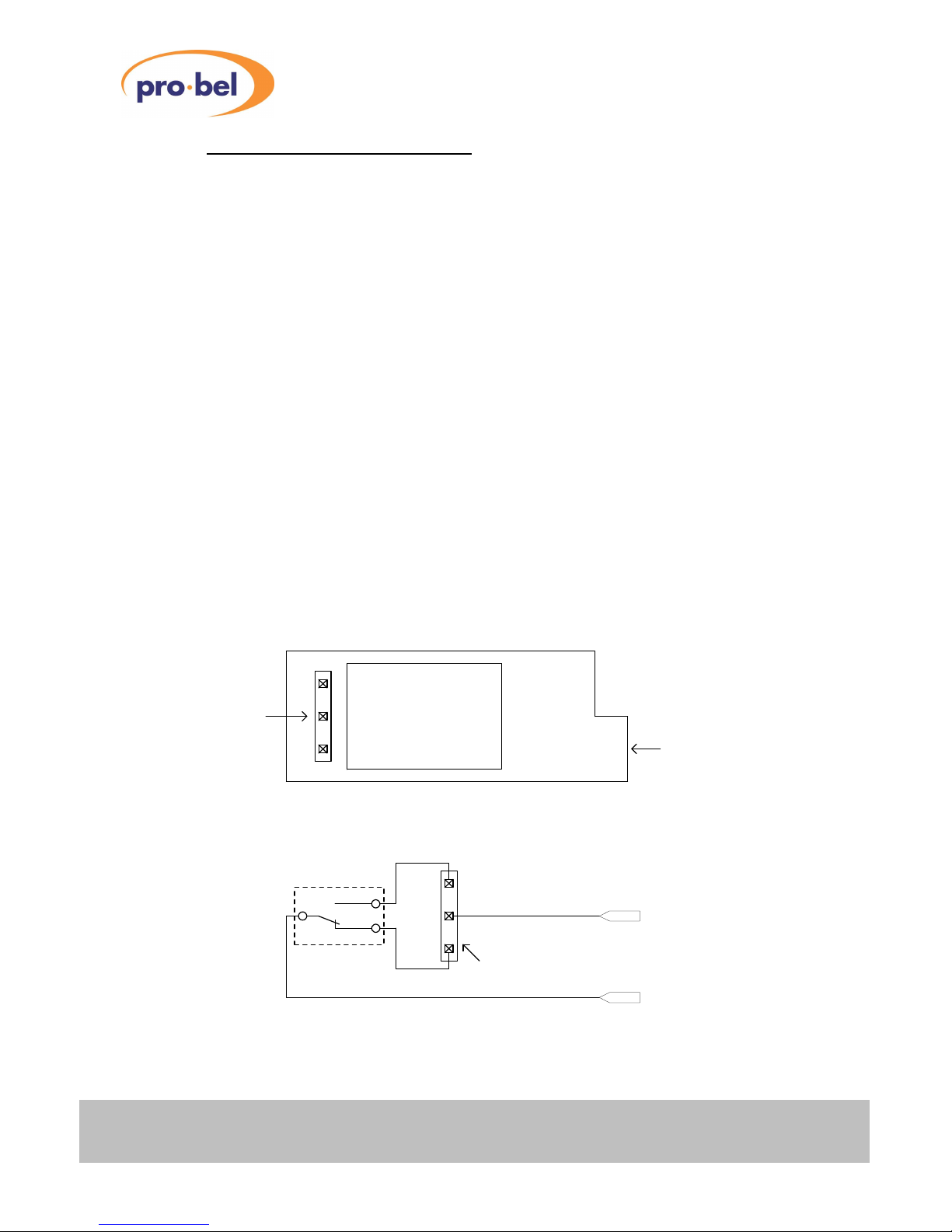
2. GENERAL PURPOSE OUTPUTS
2.1 Description
Depending on the actual board configuration, the V1679 supports up to 16 General Purpose Outputs. Each
Output is implemented as an earth-free, dry contact Relay switch. Each switch can be configured to operate
either in a 'Normally Open' (short: NO) mode, or in a 'Normally Closed' (short: NC) mode.
The Relays can be identified as little black cubes, lined up in either one group (V1679/IO, Group B only) or
two groups (
V1670/OP
Jumpers can be found in front of each Relay. Both Jumper positions (NC or NO) are clearly marked on the
board's silk-screen. The factory default setting for each output is 'Normally Open'.
A Relay will change its state, i.e. its contact will be closed (or opened, depending on the actual Jumper
position!), when either being triggered at the far end (remote site) by a state change of the corresponding
General Purpose Input, or locally via DART.
The polarity of the received control bit for any given output is application dependent, hence an unambiguous
relationship between input and output polarities doesn't exist. One might have to experiment with the NO/NC
Jumper settings in order to get the output polarity right. In case of a power failure however, the Relays will fall
back into their default state as configured by the NO/NC Jumpers because they are non-latching. The last
known 'good' state of each output will be latched in case of a broken transmission line or in case of
disconnecting the transmitter at the far end. The Outputs will resume switching as soon as the connection is
re-established. Note that the Relays are not suitable for switching high-current loads or RF signals.
2.2 Configuration
Each relay within a group is clearly numbered (A1..A8 or B1..B8). Please see section 5.2 'Electrical
Interfaces' to find the corresponding signal pairs for each output at the rear connector.
, Group A and B) at the rear connector end of the board. The output configuration
Normally Open /
Normally Closed
Jumper
NC NO
Relay Contacts
Relay
Board Layout
NC NO
Circuit Diagram
Jumper
B5
GPIOn-
Rear Panel
Connections
GPIOn+
GPI Output
Group Name & Number
Figure 1 : General Purpose Outputs (Circuit Diagram)
6 Issue 1

VISTEK V1679 single-mode fibre
data transceiver
2.3 Output Specification
Number of Outputs:
V1679/IO: 8 Earth-free, dry contact Relay switches
V1679/OP: 16 Earth-free, dry contact Relay switches
Contact configuration: Normally Open (NO) or Normally Closed (NC)
Contact material: Ag + Au Clad
Contact rating: 0.5A @ 24Vd.c. max.
Maximum operate time: 5 ms
Maximum release time: 5 ms
Maximum bounce time: 6 ms
HU-V1679 7
VISTEK V1679 single-mode fibre
data transceiver
3. GENERAL PURPOSE INPUTS
3.1 Description
Depending on the actual board configuration, the V1679 supports up to 16 General Purpose Inputs.
A V1679/IO features 8 General Purpose Inputs in addition to its 8 General Purpose Outputs, whereas a
V1679/IP comes with 16 Inputs and no Outputs.
Each of the Inputs comprises an Opto-Isolator with integrated Schmitt-Trigger Buffer, amongst other features,
such as:
Jumper configurable on-board input biasing (+5V or +12V)
•
• Jumper configurable short to ground
• On-board, 100 Ohm current limiting resistor for Opto-Isolator
• Reverse polarity protection
• Wide input current range
High speed (up to 1Mb/s)
•
Various configuration options allow straightforward interfacing of the GP Inputs to a variety of 'driving'
sources'. A driving source can be as simple as a push button, an 'Open Collector' output or a TTL/CMOSlevel buffer with a current-sinking/sourcing capability of as low as ±4mA. Extra series resistors might be
required when using a voltage source of > 7V in order to limit the forward current of the Emitter Diode inside
the Opto-Isolator. Please check with your technical department or contact Vistek for a suitable solution.
Examples of different interfacing techniques will be shown later.
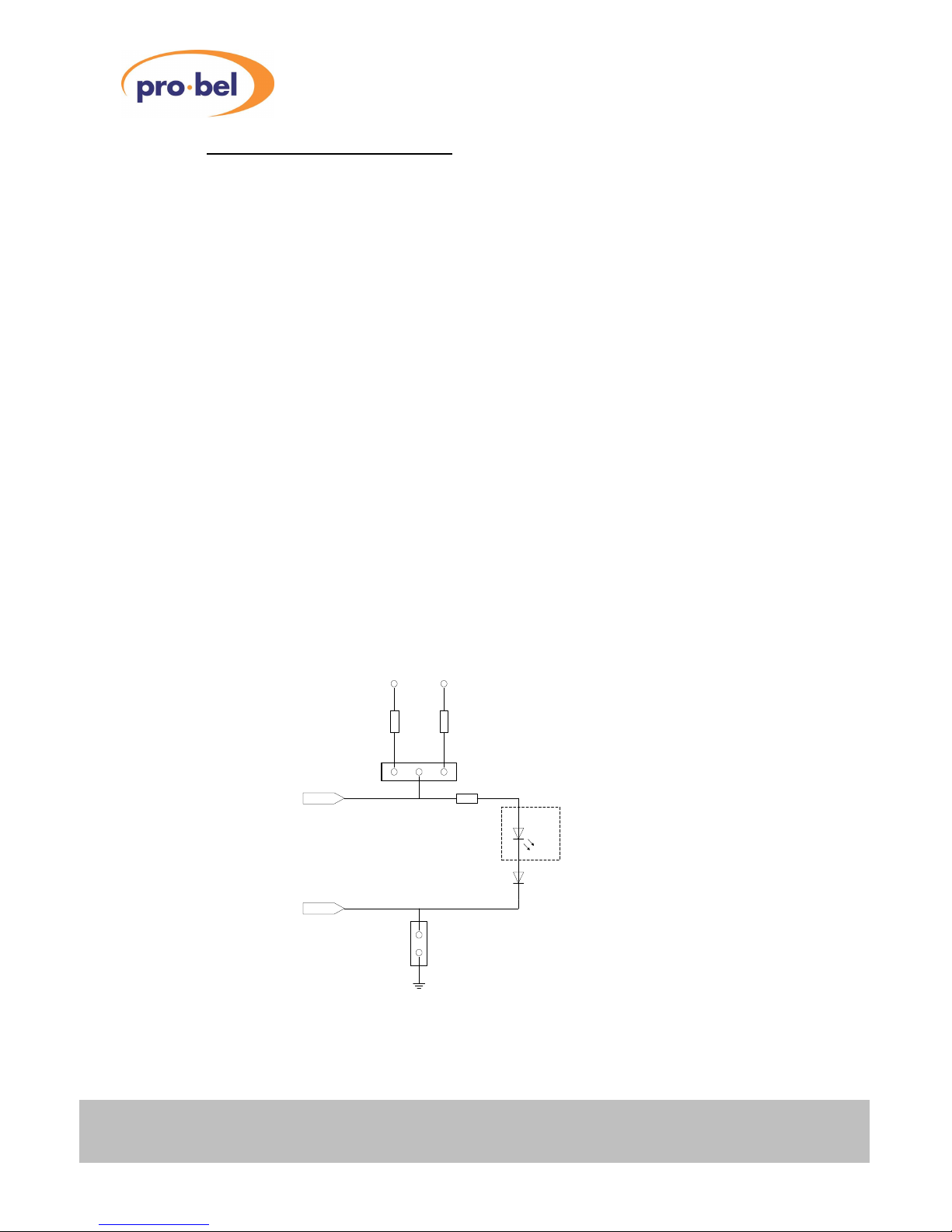
3.2 Configuration
The following circuit diagram shows the input circuit of each General Purpose Input. Understanding the
diagram will help in finding the proper configuration for a specific application.
On-board power supplies
+5V +12V
390R 1K8
Input Bias Voltage Selection Jumper
GPIOn+
From/To 44-way High Density D-Type Connector
GPIOn-
Notes:
Board GND = Chassis GND
Always provide a proper return-current path for your signal!
100R
Short to GND Jumper
Emitter Section of Opto-Isolator:
Forward Voltage VF:1.5V (max) @ IF = 10mA
Turn-On Threshold Current I
Continous Forward Current IF:60mA (max)
1N4148
Protection Diode:
Forward Voltage VF: 1.0V (max) @ IF = 10mA
:1.6mA (max)
F(ON)
Figure 2 : General Purpose Inputs (Circuit Diagram)
8 Issue 1
VISTEK V1679 single-mode fibre
+
−
100
data transceiver
When driving the Opto-Isolator from an external voltage source, one must check that the forward current
through the Light Emitting Diode (LED) inside the Opto-Isolator does not exceed 60mA. Otherwise, the OptoIsolator can be permanently damaged or even destroyed.
The current IF through the LED is determined by the Input Voltage VIN supplied between a GPIOn+ and
GPIOn- connector pin pair, the forward voltage of the LED V
V
having an extra protection diode is because of the relatively low reverse (breakdown) voltage of the LED,
which is 6V (typ), compared to 75V (min) of a 1N4148 silicon diode. This makes the GP Inputs fairly robust
against accidentally reverse biased input pins.
By applying Ohm's law, the forward current IF through the LED can be calculated as follows:
(which is in series with the LED), and the on-board 100Ohm current limiting resistor. The reason for
F 1N4148
=
F
I
VVV
)( 1N4148 FLED FIN
, the forward voltage of the protection diode
F LED
Ω
Considering the worst-case scenario, by taking V
unless an extra current limiting resistor in series to the 100 Ohm is provided.
(min) and V
F LED
(min), VIN must not exceed 7.5V,
F 1N4148
WARNING!
The maximum, continuous current through the Opto-Isolator's LED must not exceed 60mA!
Using the on-board generated forward bias supply for the LED (+5V or +12V), the current through the LED is
limited to about 5mA. This means that driving an Input with an Open Collector Driver for instance, the Driver
must be capable of sinking at least 5mA!
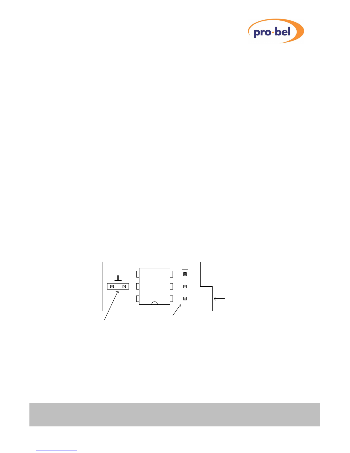
The silk screen on the PCB identifies each Input by its Group Name (A or B) and its number (1..8).
The configuration Jumpers for each GP Input are located closely to the corresponding Opto-Isolator IC. The
Jumpers are positioned as follows:
Board Layout
Short-to-GND
Jumper
Figure 3 : General Purpose Input Jumper Locations
HU-V1679 9
Opto-Isolator
On-board
Input Bias Voltage
Jumper
GPI Input
5V 12V
A5
Group Name & Number
VISTEK V1679 single-mode fibre
data transceiver
3.3 Examples for Driving V1679 GPI Inputs
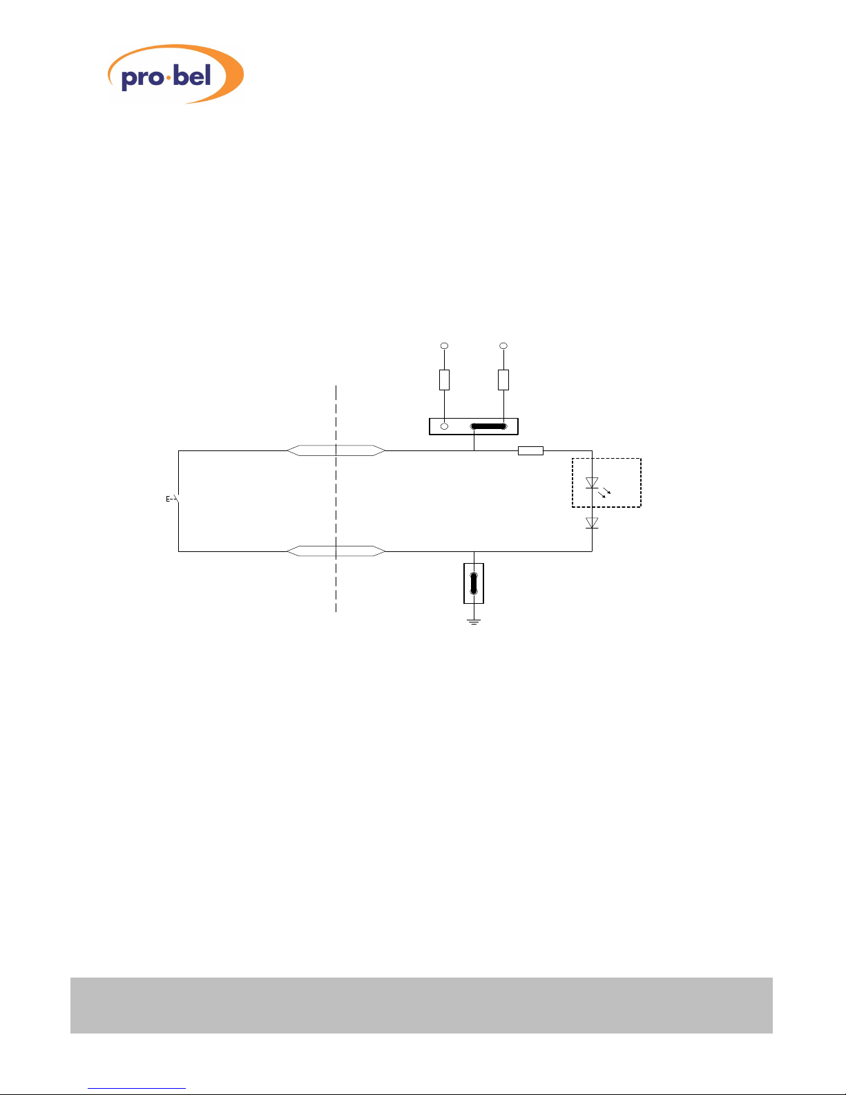
3.3.1 Push Button or Relay Driven Switch
A Push Button is a simple example of how a GPI Input can be driven. One should be aware that when using
any type of mechanically actuated switch, the input signal could bounce for several milliseconds before it
reaches a stable state. This implies that the received bit at the far end of the fibre link is unstable for the
same period of time.
The built in Schmitt-Trigger Buffer in the Opto-Isolator can only 'tidy up' slow rising edges, but it cannot
suppress heavily bouncing input signals.
On-board power supplies
+5V +12V
390R 1K8
Push Button Switch
or mechanically
actuated Switch
(Relay)
Rear Connector SideBoard Side
Note:
The LED is permanently 'ON' as long as the Push-Button is open.
By closing the switch, the LED will be shorted and goes 'OFF'.
Figure 4 : Example 1
GPIOn+
GPIOn-
Input Bias Voltage Selection Jumper
100R
1N4148
Short to GND Jumper
(short)
10 Issue 1
 Loading...