

VISTEK V1651, V1653, V1652, V1654 User Manual

VISTEK V165X SERIAL DIGITAL
VIDEO ROUTER MODULE
USER GUIDE
www.pro-bel.com
1

VISTEK V165X serial digital
video router module
Contents
1. INTRODUCTION........................................................................................................3
1.1 Description.......................................................................................................3
2. INSTALLATION.........................................................................................................4
2.1 Rear Panel Connections.................................................................................4
2.2 Hardware..........................................................................................................5
2.2.1 Switch and Link Settings.......................................................................5
3. OPERATION..............................................................................................................9
3.1 Front Panel Indication.....................................................................................9
3.2 Indicators.......................................................................................................11
3.3 Controls..........................................................................................................12
2 Issue 1

VISTEK V165X serial digital
video router module
1. INTRODUCTION
1.1 Description
The V165X Serial Digital Video Router Module provides a platform on which several different types of router
may be built. All the variants can handle the four main video standard frequencies of 143, 177, 270 and 360
Mbits/s. The outputs are fully re-generated.
The range consists of :-
The V1651 2x1 SDI router with automatic signal error detection and changeover.
The V1652 8x1 SDI router.
The V1653 8x1 SDI router with synchronous switching.
The V1654 8x8 SDI router with Output monitoring.
All the routers can be fed with an analogue external reference signal, but this reduces the 8x1 routers to
7x1's due to the limited rear panel space. If the external reference is not fitted the switching reference will be
taken from the currently selected output, so vertical interval switching will be maintained between sources of
the same relative timings. The switching line used is user selectable and may be field or frame based.
The routers are all provided with front panel controls and indicators. All the modules are provided with the
required interface logic for the Dart remote control system and also a simple remote panel interface. (See
V1650 Remote Control Manual).
The V1651, 2 & 3 modules are 3U high cards and are designed to fit in the V1601 or the V1603 racking
systems. The V1654 is also 3U high modules, but is double width, so will only fit in the V1603 rack.
The V1651 and V1653 are designed to have clean switching between the sources. The routers achieve this
by timing the new source as close to the reference as possible, before switching. The reference is obtained
from either the External Reference input (I/P 8), or if not present the currently selected source. (The V1651
may have its clean switching turned off if a reference is not available.)
Due to the sources having differing clock phases it is only possible to synchronise the sources within one
clock cycle, so if the reference is taken from the sources rather than an external reference the delay through
the router can progressively change as sources are selected.
HU-V165X 3
VISTEK V165X serial digital
(IN)
(IN)
(IN)
(IN)
video router module
2. INSTALLATION
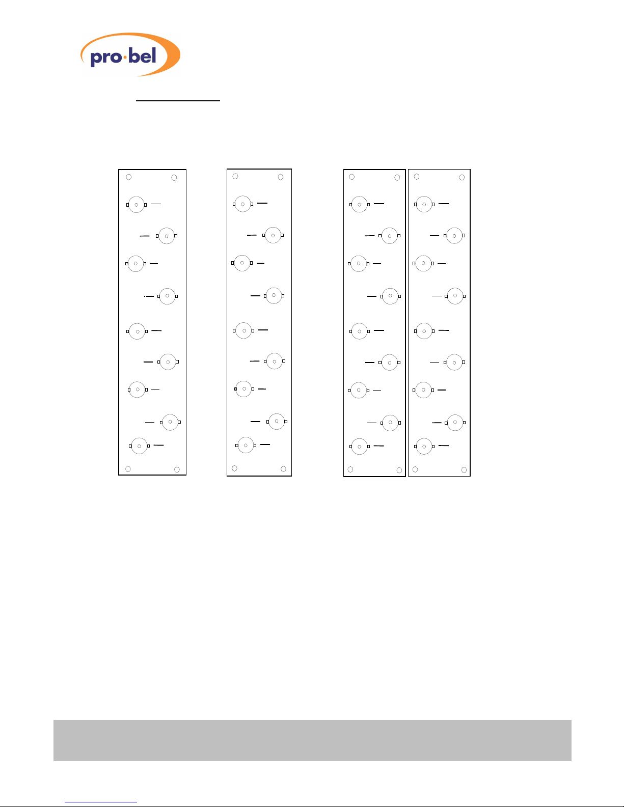
2.1 Rear Panel Connections
V1651 V1652, V1653 V1654
SD1
(IN)
SD
(OUT)
SD1
(IN)
SD2
(IN)
SD3
(IN)
SD
(OUT)
SD2
(IN)
SD1
(OUT)
SD3
(OUT)
REF
SD1
(IN)
SD2
(OUT)
SD3
(IN)
SD4
(IN)
SD5
(OUT)
SD6
REF
SD7
SD8
(IN)
/REF
SD7
(OUT)
SD4
(OUT)
SD5
(IN)
SD6
(OUT)
SD7
SD8
(OUT)
Power
The power is picked up by the input connector panel from the frame to feed the router. The nominal power
consumption of each router is:V1651 8.5W
V1652 6W
V1653 10W
V1654 13.5W
If the V1650 Remote Control Panel Interface is connected the power consumption of the router module is
increased by 0.5W.
SD1-8 (IN)
The Serial Digital Inputs are passed straight through the rear module and terminated in 75 Ohms on the main
module. Input 8 on the V1652 and V1653 is shared with the reference input and a zero ohm resistor is fitted
on the module to set the operational mode. (R102 - I/P 8, or R103 - Ref). Inputs 2, 4, 5, 6 & 7 are not used
on the V1651 and input 8 is set on the main module to the reference mode.
4 Issue 1
MON
(OUT)
SD2
(IN)
SD4
(IN)
SD6
SD8
(IN)
 Loading...