

VISTEK V1640A Installation And Operation Manual

29 October, 2003 v1640Aom_b.doc / B Page 1 of 11
V1640A
SDI VIDEO SYNCHRONISER
INSTALLATION and OPERATION
© Vistek Electronics Ltd
Filename: v1640om_b.doc
Issue
B
October, 03
VISTEK Electronics Ltd
Wessex Rd
Bourne End
Buckinghamshire, SL8 5DT
ENGLAND
Tel. +44 1628 531221
Fax. +44 1628 530980

1 March, 2005 v1640Aom_b.doc / B Page 2 of 11
SDI VIDEO SYNCHRONISER
INSTALLATION AND OPERATION
1. DESCRIPTION
The V1640A SDI Video Synchroniser is a full broadcast specification Frame Synchroniser forming
part of the Vistek V1600 range of interface products. It is a 3U high module which can be fitted to
either the 1U V1601 or 3U V1603 chassis from which it receives its power. It replaces the existing
V1640 module with which it is fully compatible. The main improvements over its predecessor is that
local adjustment of the timing offsets is possible without removing the unit from the rack, and full
control over DART has been implemented. There are some other minor operational improvements
which are detailed later in this manual. Mechanically the unit has been improved since it is now built
on a single PCB, rather than using two.
When fitted in either the V1601 or the V1603 racks passive rear modules are required to interface to
the outside world. Different rear modules are required for the two chassis. The rear modules are
common to many other Vistek video modules.
The unit automatically operates in either 625/50 or 525/60 formats depending on the input signal.
Normally the Black and Burst reference will be of the same standard, but in the case of it being
different the unit will operate according to the SDI input and set itself to minimum delay. This has
been implemented for use in those areas where the input signal may originate in either standard,
and will be either synchronised or passed through a Standards Converter which will in itself
synchronise the signal.
There is a choice of action in the event of signal loss. The unit can either Freeze or cut to Black.
Provided a reference is connected the output timing is not affected by the loss of the input signal .
When operating in with 625/50 signals the unit works as a Line Synchroniser. This means that it
can handle cuts on the input signal with less picture disturbance than usual, provided the cut is done
on one of the designated switching lines, 6 or 7. The relative timing of the two signals on each side
of the cut should be within approximately 20 lines.
A TTL output is available which indicates the amount of delay being applied to the signal. This can
be used in a suitable tracking audio delay (such as the Vistek V1639) to ensure that video and audio
can stay timed correctly.
The front panel enables direct control of most functions within the unit. It is also used to switch
control from the front panel to the remote DART system. The unit contains non-volatile memory so
that when any parameters are set up locally they are still available after a power-down. Since the
timing offsets are often so important to an installation, an internal DIL switch is available to lock
them out. This prevents ‘accidental’ adjustments of the timing. Adjustment is always available over
DART, since the control system has its own built in safeguards.
The user may selectively pass or blank non-active video signals. Separate control is available over
the Vertical Blanking data, such as Teletext or Insertion Test Signals, and ancillary data, such as
embedded digital audio.
When operating in 525 mode later versions have the ability to selectively blank Line 21 on either
field to remove Closed Caption information. This can only be donelocally on a DIL switch.
The unit is fully controllable over the DART remote control system.
The output of the unit has full EDH signals applied, but there is no EDH detection on the input.
1 March, 2005 v1640Aom_b.doc / B Page 3 of 11
2. INSTALLATION
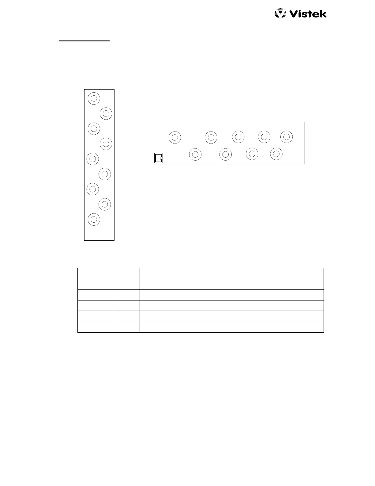
2.1 REAR PANEL
Two rear panels are available depending on the type of chassis into which the unit is fitted:
3U (V1603)
SDI
SDI1
SDI2
SDI3
VIDEO
REF
DELAY
1U (V1601)
SDI
IN
SDI1
SDI2
SDI3
VID. REF
DART
DELAY
2.2 REAR PANEL CONNECTIONS
SIGNAL CONN DESCRIPTION
SDI IN BNC SDI Video Input
SDI 1, 2, 3 BNC 3 off SDI Video Outputs
DELAY BNC TTL Delay Pulse
VID. REF BNC
Video Reference Input. An internal switch enables 75Ω termination.
DART RJ45 DARTNET connection. Only used in on position in 1U rack.
2.3 POWER CONSUMPTION
The V1640A power consumption is 6.5W
2.4 INSERTION DELAY
The insertion delay is, of course, variable over a frame. If the input and reference frame rates are
different then the delay will vary. At some stage there will be a frame drop or a frame repeat and
just before or just after there will be a point of minimum insertion delay. There is hysteresis in the
frame discontinuity, to avoid rapid toggling, so the minimum delay depends on the drift direction:
Minimum Delay (Increasing):
1.65µs
Minimum Delay (Decreasing):
1.05µs
The minimum delay, as set from the front panel or through DART, is 1.7µs.
1 March, 2005 v1640Aom_b.doc / B Page 4 of 11
2.5 DELAY O/P
The Delay O/P signal is a TTL levels rectangular wave. The period is the same as the frame rate
(40ms for 625/50 and 33.3ms for 252/60) but the mark-space ratio varies according to the amount of
delay.
Frame
Delay
The minimum pulse width, either positive or negative, is 37ns.
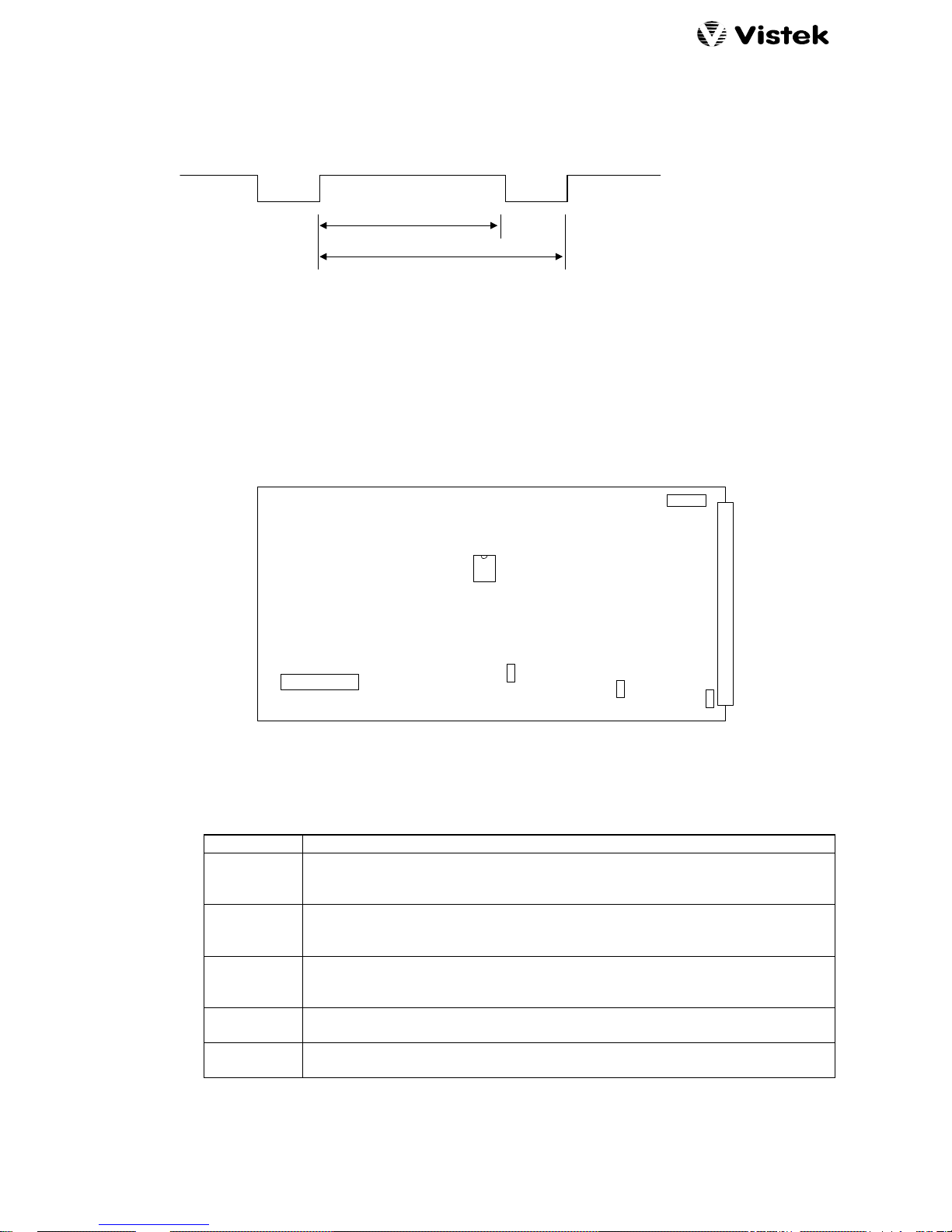
2.6 INTERNAL HARDWARE
2.6.1 MAIN BOARD
FRONT PANEL
REAR CONNECTOR
PROM
DIL SWITCH
LK1
SW5
U15
FS1
18
VR1
VR2
The significant items on the main board are described here:
FS 1 Input power fuse, 3A.
SW 5 Internal configuration switches, S1 at the left. See section 3.11 for details.
Note that each switch is UP or DOWN. Ignore the ‘OFF; indication on the
switch block.
U15 The 8 pin DIL PROM that contains the firmware for the programmable device.
In the event of upgrades in the field it is most likely that this is the device that
will need to be changed.
LK 1 Enables termination of the video reference:
UP = Open
DOWN = Terminated
VR 1 Factory adjustment for reference standard select.
Adjust for 18ms on TP 49
VR 2 Factory adjustment for oscillator centre frequency.
Adjust for 27MHz on TP 39.
 Loading...