

VISTEK V1634A, V1634D Installation And Operation Manual

2 March, 2005 V1634OM.DOC Page 1 of 12
V1634/A
V1634/D
SDI AUDIO DEMULTIPLEXER
INSTALLATION and OPERATION
© Vistek Electronics Ltd
Filename: V1634OM.DOC
Issue: Rev. B1
Date February, 05
VISTEK Electronics Ltd
Wessex Rd
Bourne End
Buckinghamshire, SL8 5DT
ENGLAND
Tel. +44 1628 531221
Fax. +44 1628 530980

2 March, 2005 V1634OM.DOC Page 2 of 12
This page is intentionally blank

2 March, 2005 V1634OM.DOC Page 3 of 12
SDI AUDIO DEMULTIPLEXER
INSTALLATION AND OPERATION
1. DESCRIPTION
The V1634A Audio Demultiplexer is a full broadcast specification extractor of audio data from an
SDI data stream. It forms part of the Vistek V1600 range of modular interface products. It is a 3U
high card which is fitted into either the 1U V1601 or 3U V1603 chassis from which it receives its
power. It is an improved and upgraded replacement for the V1634. The main improvements are a
single board construction, and the fitting of audio sub-boards. This means that either digital AES or
analogue outputs can be provided. The choice is made by fitting one of two available sub-modules.
There is an audio multiplexer module, the V1633A, which replaces the V1633 and is fully compatible
with the V1634A.
In both the V1601 and V1603 racks passive rear modules are required to interface to the outside
world. For each rack two rear modules are available depending on whether the audio is required to
be analogue, digital AES balanced or digital AES unbalanced. The rear modules are common for
the V1634A and V1633A.
The SDI video may be either D1 or D2 and either 625/50 or 525/60. The unit automatically detects
the standard and format of the input signal and operates accordingly.
If the analogue output module has been fitted then all four audio outputs are available as balanced
signals. If the digital AES output option is fitted then the AES signals are available either balanced
or unbalanced, depending on the type of rear module that is fitted to the rack.
The unit extracts audio that has been embedded into a SDI video data stream according to SMPTE
272M. Any one of the available audio groups may be extracted; the number depend on whether the
signal is D1 or D2. Unlike de-multiplexers from some other manufacturers the audio does not need
to be synchronous with the video into which it has been embedded. This makes the use of
embedded audio within a studio area much simpler to implement. This means that within
SMPTE 272M it operates at Levels A, B, C and D. The overall design is particularly rugged in
respect of use with a wide range of audio multiplexers, which has proved particularly important since
there have been many ‘interpretations’ of SMPTE 272M.
Another facility to assist the installation in a real environment is the ability to lock an AES output to
an external reference. (With an analogue output the reference serves no purpose.) The external
reference may be either a Black and Burst video, another AES signal, or the SDI video itself can be
used.
There are three SDI outputs which are re-clocked versions of the SDI input. If the signals are D1
then the ancillary data may be stripped off the SDI output signal. This facility is not available for D2
signals.
The unit is fully controllable over the DART remote control system.
The output of the unit has full EDH signals applied, but there is no EDH detection on the input.
2 March, 2005 V1634OM.DOC Page 4 of 12
2. INSTALLATION
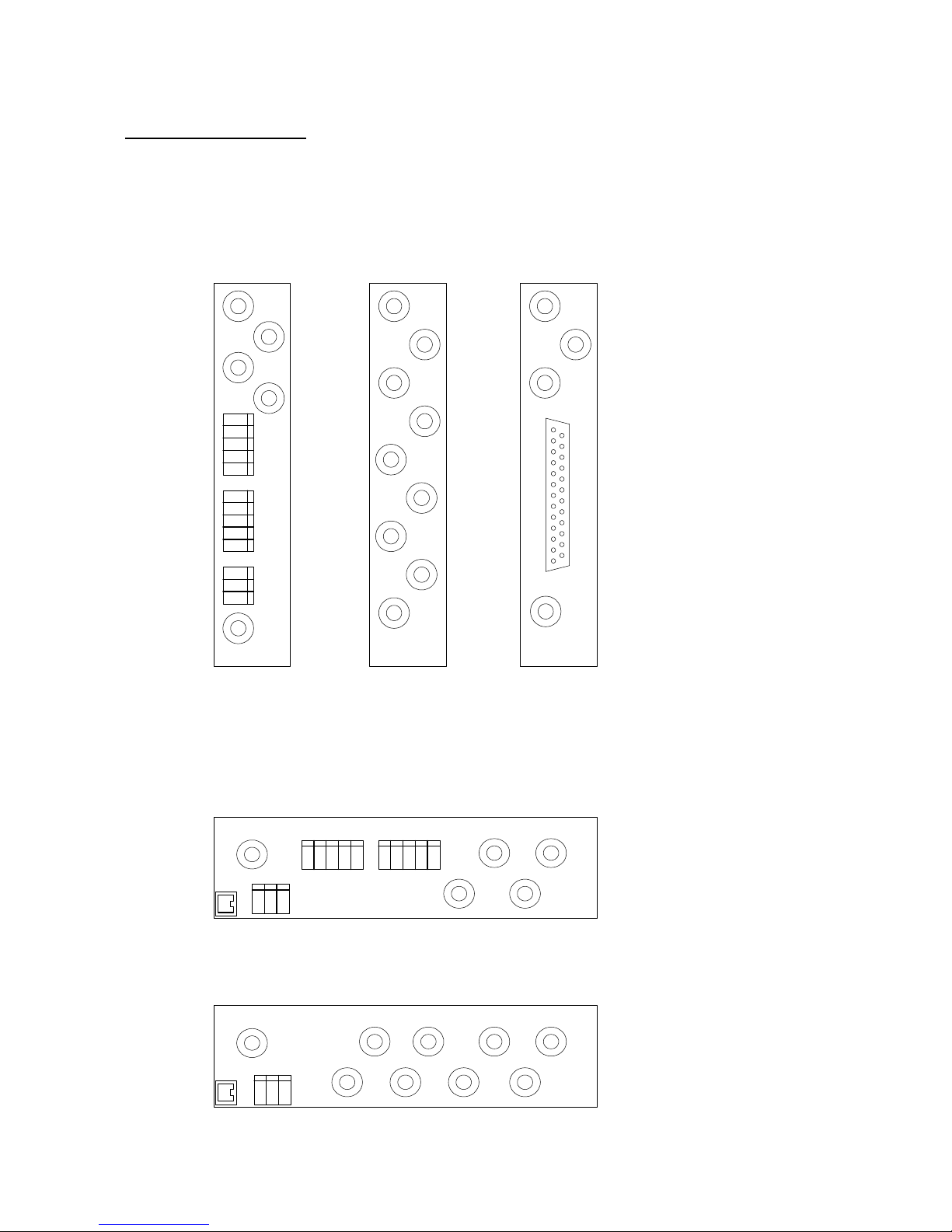
2.1 REAR PANEL - 3U
Two 3U rear panel options are available, depending on the output format. They are shown below:
AES UNBALANCED
SDI
SDI1
SDI2
SDI3
VIDEO
REF
SDI
SDI1
SDI2
SDI3
L/AES
R
L/AES
R
AES
REF
VIDEO
REF
+
-
+
-
s
s
+
-
s
-
-
+
+
AES A
AES B
AES
REF
ANALOGUE or
AES BALANCED
A
B
SDI
SDI1
SDI2
VIDEO
REF
Audio IO
D-TYPE
2.2 REAR PANEL - 1U
AES UNBALANCED
ANALOGUE or
AES BALANCED
SDI
IN
SDI1
SDI2
SDI3
L/AES
R/AES
VID. REF
+
-s-
+
AB
DART
AES
REF
+
-
s
L/AES
R/AES
+
-s-
+
SDI
IN
SDI1
SDI2
SDI3
VID. REF
DART
AES
REF
+
-
s
 Loading...