

VISTEK V1629 Installation And Operation Manual

17 February, 2005 V1629OM.DOC/ A Page 1 of 10
V1629
DUAL MONITORING ENCODER
INSTALLATION and OPERATION
© Vistek Electronics Ltd
Filename: V1629om.doc
Issue: A
Date: December 2000
VISTEK Electronics Ltd
Wessex Rd
Bourne End
Buckinghamshire, SL8 5DT
ENGLAND
Tel. +44 1628 531221
Fax. +44 1628 530980
Web: www.vistek.tv

1 March, 2005 V1629OM.DOC/ A Page 2 of 10
V1629 DUAL MONITORING ENCODER
INSTALLATION AND OPERATION
1. DESCRIPTION
The V1629 is a two channel monitoring encoder which converts SDI signals to analogue colour
composite ones. It is based heavily on the existing V1627, but has two completely independent
channels. It is a 3U high Eurocard which can be fitted into either a V1601 or V1603 chassis from which
it receives its power. A passive rear module is required for all external interconnections; different ones
are used for the V1601 and V1603 chassis.
For each channels there is an active, reclocked, digital output and two analogue composite colour
output signals. Since there is a re-clocked output the unit can effectively be put in series with the signal
path, avoiding the need for a DA. The analogue outputs conform to the published specifications of the
various colour systems, but the post DAC filtering is optimised for the viewing rather than the
transmission environment. Since the coder portion is intended for monitoring purposes it uses only 8
bits from the SDI data stream. The data reduction is done using the Dynamic Rounding technique,
which avoids the visibility of rounding or truncation errors.
The two analogue CVBS outputs from each channel can be switched over to Y/C. In this case the full
CVBS is not available (i.e. it is not possible to have CVBS and Y for example).
Each channel operates automatically on both possible input formats, 625/50 and 525/60. Within each
format two colour standards are available as follows:
625/50 : PAL I or PAL N
525/60 : NTSC or PAL M
Which standard is used can be set locally on a DIL switch on the PCB or remotely over the DART
remote control system.
The two channels are quite independent and can be operating in either the same or different colour
standards and/or different formats. Also any channel can be producing CVBS while the other does YC.
If NTSC is the chosen colour standard then it can be switched between the normal standard, as used in
the US and most other NTSC countries, or to the Japanese variant which does not have Setup, and
therefore slightly different levels as well. This can also set on the DIL switches or over DART.
As well as the encoder functions each channel of the unit can also produce a PLUGE test signal
(Programme Line-Up Generating Equipment). This is useful for setting up a bank of picture monitors for
the same brightness and contrast. PLUGE can be selected on the front panel or since this unit may be
used in quantity associated with a bank of picture monitors it is possible to remotely select PLUGE on a
GPI input. This is the only control that is common to both channels But conversely since this could
disturb the output picture, a DIL switch on each channel can disable PLUGE generation from any source
(switch, DART or GPI). The unit is not an SPG so cannot generate PLUGE without a valid input signal.
The front panel has several LEDs and switches. Two LEDs are common with all V1600 modules and
show the presence of on board regulated power and remote access from the DART system. Other
LEDs indicate the operating standard of each channel, if present, whether YC is selected and whether
PLUGE is on the outputs. There are two switches, one for PLUGE and the other for the control source –
Local or Remote. (The GPI control is always ‘live’ so does not need to be selected.)
1 March, 2005 V1629OM.DOC/ A Page 3 of 10
2. INSTALLATION
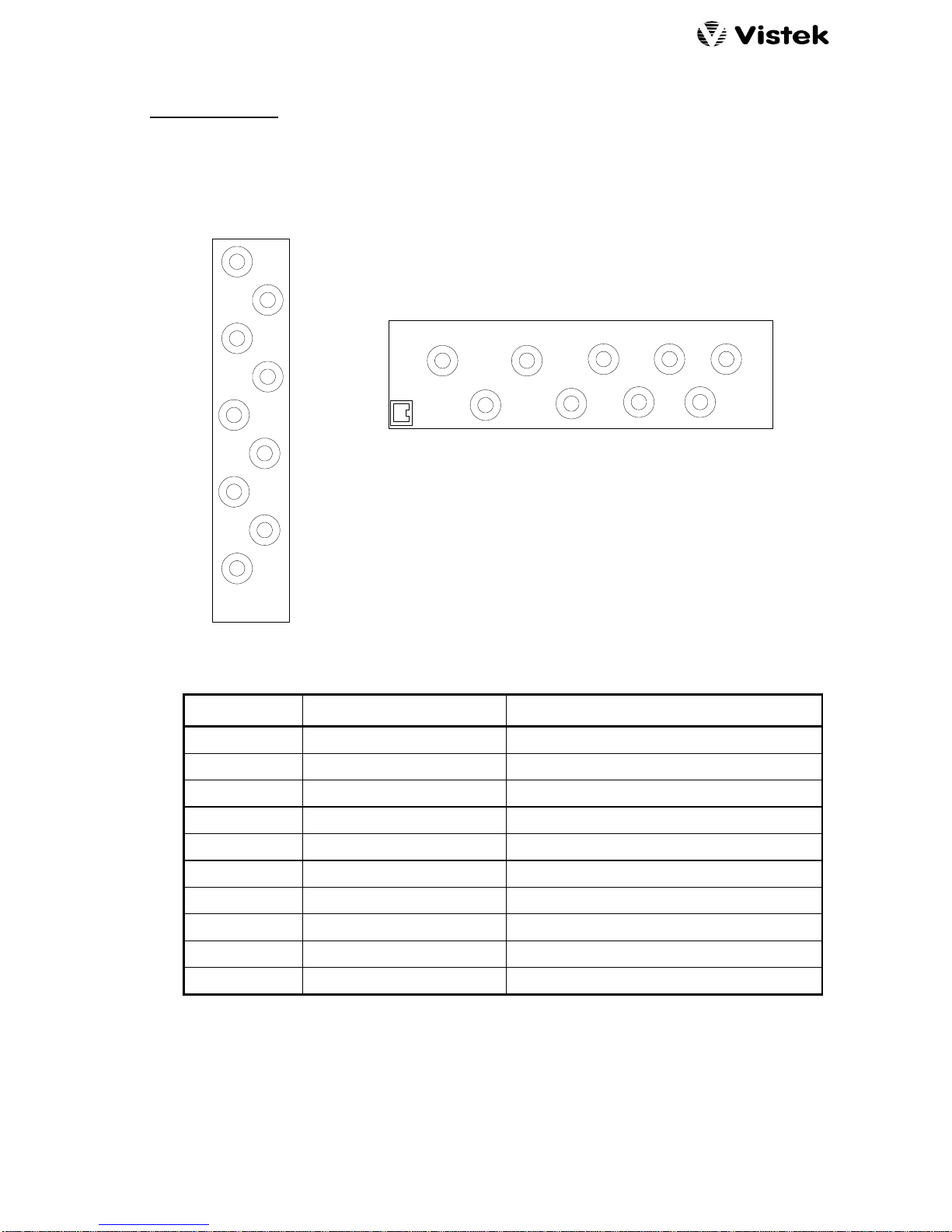
2.1 REAR PANEL CONNECTIONS
The two available rear panels are shown below:
3U (V1603)
1U (V1601)
DART
SDI A I/P
SDI A O/P
CVBS A1
CVBS A2
GPI
CVBS B2
CVBS B1
SDI B O/P
SDI B I/P
SDI B I/P
SDI B O/P
CVBS B1
CVBS B2
GPI
CVBS A2
CVBS A1
SDI A O/P
SDI A I/P
SIGNAL SOURCE COMMENTS
POWER The Rack ~7.5W
SDI A I/P SD (IN) Sourcing cable length up to 200m
SDI A O/P Reclocked version of SDI A Driving cable length up to 200m
CVBS A1 Colour Composite or Y Channel A: CVBS or Y
CVBS A2 Colour Composite or C Channel A: CVBS or C
GPI External Grounding GPI control of PLUGE
CVBS B2 Colour Composite or C Channel A: CVBS or C
CVBS B1 Colour Composite or Y Channel A: CVBS or Y
SDI B O/P Reclocked version of SDI A Driving cable length up to 200m
SDI B I/P SD (IN) Sourcing cable length up to 200m
 Loading...