

VistaPure 3000 Installation Manual & Owner's Manual
Ultra Pure Water System
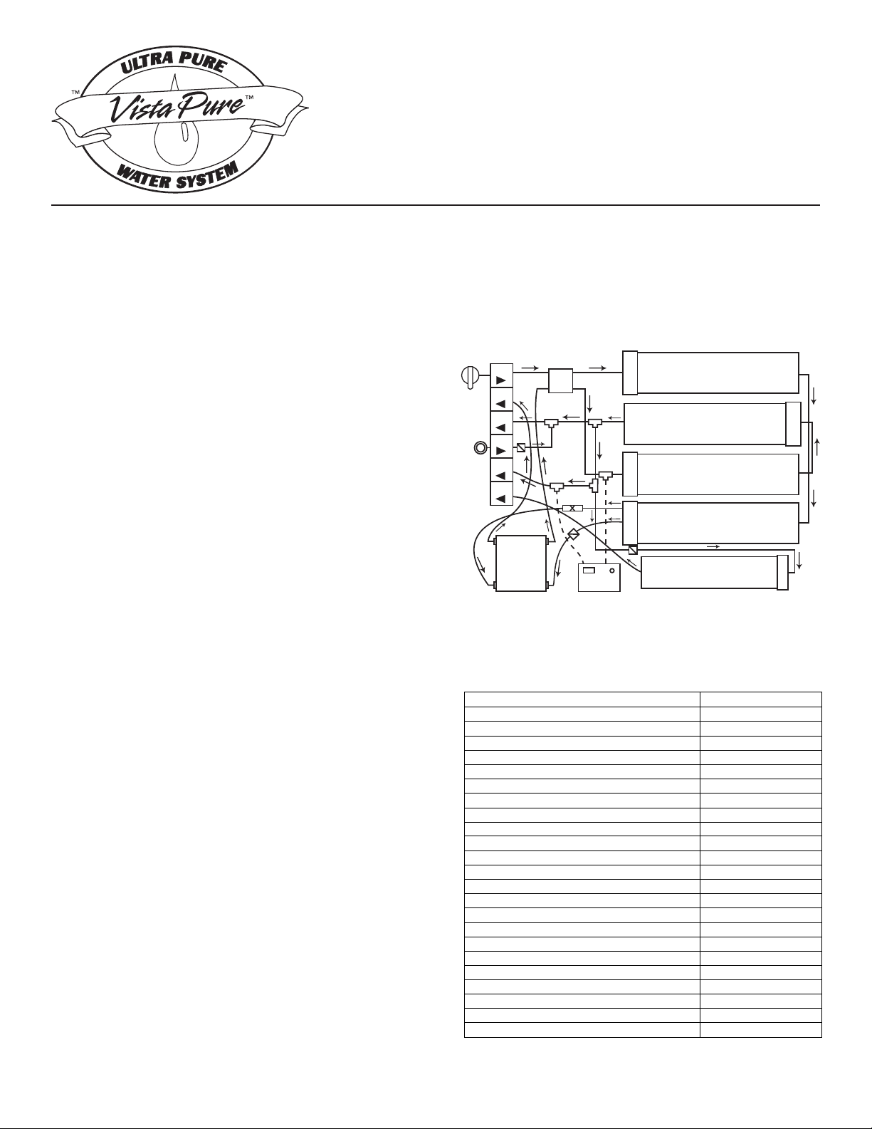
Prefilter
D/I #2
D/I #1
Hyperfiltration
Polishing
1
3
2
5
C
H
B
101
102
103
104
105
106
A
K
I
4
Maximum Operating Temperature
100° F
Minimum Operating Temperature
45° F
isp 001erusserP gnitarepO mumixaM
tseb isp +04 – isp 03erusserP muminiM
5.8 – 5.6egnaR Hp lamitpO
Maximum Total Dissolved Solids (TDS) 500
5.9 – 5.5egnaR Hp mumixaM
mpp 171/rg 01ssendraH tneulfnI mumixaM
mpp 50.0esenagnaM tneulfnI mumixaM
mpp 1.0norI tneulfnI mumixaM
Maximum Influent Hydrogen Sulfide none
Maximum Influent Chlorine/Chloramine 2 ppm
Maximum Daily Output (12 hours) 25 gal (94 L)
Stage 1 Prefiltration Element Service Life 1 year max
Stage 1 Prefiltration Replacement Order # R5633
Stage 2 Hyperfiltration Element Service Life 3-5 years
Stage 2 Hyperfiltration Replacement Order # R3080
Stage 3 Deionization Element Service Life 4-18 mo – See pg 7
Stage 3 Deionization Replacement Order # R5662
Stage 4 Polishing Filter Element Service Life 1 year max
Stage 4 Polishing Replacement Order # R2551
System Dimensions (W x H x D) 22”x16”x 5”
”61 x ”5.9)H x aiD( snoisnemiD knaT
Approximate Shipping Weight (Dry-2 Cartons) 33 lbs
Model 3000
Installation Guide
& Owner’s Manual
The VistaPure Ultra Pure Water System is designed
to produce two grades of high-purity water – 1) distilledquality for use in your autoclaves and 2) non-corrosive water
for use in bottle systems and for other uses. It is critical that
water used in autoclaves be virtually free of dissolved solids
and contaminants in order to protect the heating chamber
and to prevent build-up of contaminants that can create hard
deposits and more frequent cleanings. If poor quality water
is used, the autoclave will generally need to be re-built or
replaced at substantial cost. Water used in self-contained
dental bottle systems should be of high quality but not the
same grade as used in autoclaves since distilled-grade water
is corrosive to metals used in the construction of dental
units. The VistaPure system is designed to be built-in to
sterilization centers, cabinetry or can be simply installed in
an equipment room. In addition to use with your autoclaves,
the high purity water produced by your new VistaPure can
be used for making coffee, tea and other beverages, for
laboratory use and more.
The system provides 2.7 gallons of treated water in the
pressurized storage tank and automatically produces a new
supply as water is drawn from storage. The system does
not require electricity – it only needs a potable supply of
cold water and a drain. It is highly recommended that water
supplied to the system be free of sediment. Further, if the
source water is hard, the system ltration elements will last
longer if the water supply is softened.
Please return the Warranty / Registration form
immediately upon installation.
Always follow local plumbing codes.
Note the following specications before proceeding:
Figure 1. Front view of the VistaPure system.
VistaPure Model 3000 Specications
Although actual installation of VistaPure is quite simple, it
is recommended that a professional technician familiar with
dental operatory systems perform the installation due to the
wide variety of possible options, running of water and air
lines, drain lines, etc. He/she should be familiar with the
local plumbing codes and techniques for successful dental
equipment installations.
Please read this entire manual before proceeding with
Please make certain that anyone responsible for future
operation and maintenance of the system is familiar with
all details contained in the installation and maintenance
installation and operation.
manuals.
Please keep the maintenance manual handy for
future reference.

UNPACKING – Carefully unpack the contents of
the product carton. It should include the system,
Installation Guide & Owner’s Manual, Warranty
Registration sheet, an accessory pack and a supply
of colored tubing. Check to make certain there was
no damage during shipment. If damage is evident,
contact the shipping company or your distributor
immediately.
Installation Procedure
( Please refer to drawings that follow )
1. If the system is not already mounted in another
product (sterilization center, etc.) mount as desired
near a cold water source and 1-1/2” drain.
DATA – Locate the serial tag on the system and record
it on the blue Warranty Registration sheet. Provide
all of the information requested on the Warranty
Registration sheet and mail it immediately to Vista
Research Group, LLC upon installation. Write the
date of installation and the installer’s name on the tag
using a ne tip, permanent marker (e.g. a Sharpie®)
or some other writing instrument that will not smear.
HOW THE SYSTEM WORKS – The system is a
unique design that combines several technologies
using multiple stages to produce the highest purity
product – water with a total dissolved solids (TDS)
reading as low as zero (000).
The rst stage is a Prelter that removes sediment,
chlorine and other contaminants by physical ltration,
absorption and adsorption. Next is the Hyperltration
stage where pressure from the water source and the
non-electric permeate pump forces the water through
a semi-permeable membrane removing contaminants
at the molecular level. Contaminants are rinsed away
from the membrane and down the drain. The water
is then sent to two cartridges in series that contains
both cationic and anionic resins for removing any
remaining contaminants by a Deionization process.
The nished water is sent to a 2.7 gallon storage tank
where it is delivered on demand to the autoclave ller
wand or the bottle faucet as needed. Water running
to the secondary faucet (for lling bottles, etc.) runs
through the Polishing lter after leaving the tank
where a small amount of dissolved solids is added
back to the water to prevent corrosion.
LOCATION: The VistaPure system can be installed
nearly anywhere in the typical dental, medical, lab or
hospital setting, typically near a faucet and sink. The
system and tank are designed to t under a countertop
and connect directly to the cold water supply line and
drain. It may also be installed in any area where there
is a quality cold water supply and drain connection.
INSTALLATION: Although actual installation of
VistaPure is quite simple, you may wish to enlist the
services of a professional technician since your system
is going to be directly connected to the plumbing
system. He/she is familiar with the wide variety of
possible installation options, running of water and
drain lines, local plumbing codes and techniques for
successful equipment installations.
2. Position storage tank as near VistaPure system
board as possible.
3. Locate the white elbow tank valve in accessory
pack and attach valve to the side of the tank. Handtighten only!! Never use tools on system valves and
ttings!
4. Provide for a 1/4” connection to the cold water
supply. This is usually done using a piercing saddle
valve or compression tting.
5. Provide a 1-1/2” vertical drain riser with trap as
shown in Figure 3 or Figure 4. The Air Gap drain
tting and 1/4” push-type tting is included in the
accessory pack. The Air Gap drain tting should be
glued to the drain riser as shown. See page 6 for drain
congurations.
6. Mount the faucet on the sink or countertop deck.
The faucet & push-type faucet connector tting are
included in the accessory kit.
7. Attach colored tubing to the proper segments on the
system manifold and the appliance/device as shown
in Figure 2. When attaching tubing to the push-type
ttings, make certain all tubing cuts are straight and
free from burrs. Tubing must be rmly inserted into
the tting (11/16” plunge) to avoid leaks.
IMPORTANT NOTE: If the system is mounted
inside a cabinet, under a sink or on a sliding device,
be careful that tubes are not crushed or crimped. If
the system is on a sliding device for easy access,
make certain to create a coil with the tubes that will
allow the system to move in and out without causing
damage or restriction. See Figure 7 for the proper
coil layout.
IMPORTANT NOTE: If the VistaPure system is
to be installed remote to the autoclave(s) and/or in a
cabinet, sh the solid blue tubing behind cabinetry
to the autoclave center. The solid blue tubing and
the coiled blue tubing are to be joined with the white
1/4” x 3/8” push-type union that is already attached
to one end of the coiled tubing. Please see Figure 2.
Make certain to provide a restraint at the straight
end of the coiled tubing near the union so that when
pulling out on the autoclave wand and coiled tubing
the union connection is not stressed.
2

Extra lengths of tubing are included with each system.
Below is the tubing color code chart. Please refer to
Figure 2 for detail.
Red From Cold Water Supply
Black To Drain
Natural To and From Tank
Blue Smooth To Autoclave Area
Blue Coiled To Autoclave Filler Wand
White To Faucet
8. Cleansing the system (after all tubing connections
have been made). Find the 35 ml syringe that’s
included in the accessory kit. Place about 20-30 ml
of clean water into a small paper cup and add about
two (2) drops of standard household bleach. Stir
gently with the syringe then pull the solution into the
syringe. Remove the safety cap from the injection
port at “K” on the manifold (see Figure 2). To remove
the cap simply hold the collet back against the cap
tting and pull it away from the check valve. Inject
the solution into the Injection Port. Draw 20-30 ml of
fresh water into the syringe and also inject it into the
Port in order to push all the bleach out of the check
valve. Replace the safety cap by pushing it rmly
onto the Injection Port tube. Immediately “Open”
the Water Supply Inlet Valve “I” on the manifold and
water will begin to ow into the system lling the
tank with treated water and the bleach.
9. Allow the system to run for twenty (20) minutes.
Waste water should be running to the drain Air Gap
“D” and a pulsing / clicking sound should be heard
coming from the Permeate Pump “C.” After twenty
minutes, “Close” the Water Supply Inlet Valve “I”
on the system manifold then discharge water from
both the Autoclave Wand “F” and Faucet “G” until
Tank “E” is empty and water ow stops. The system
is now cleansed.
10. “Open” Water Supply Inlet Valve “I” and allow
it ro run until the tank is full. This will take over an
hour for the tank to completely ll. However, water
can be used anytime after about thirty minutes since
the system produces and stores up to 2.7 gallons of
water and can deliver water to both the Wand and
the Faucet even while it’s making new water. The
system capacity is about 25 gallons of production per
12 hour work day.
Monitoring TDS
Total dissolved solids (TDS) is the quantitative
measure of virtually ALL constituents found in a
particular water supply counted as parts per million
(ppm) or milligrams per liter (mg/l). Water is simply
H2O – basically, everything else found in it would
contribute to the TDS. A typical city water supply will
have a TDS reading of from 150 – 350 TDS, although
it varies greatly. The federal standard for municipal
water systems is a maximum of 500 ppm TDS. Some
rural well waters are quite often found to range from
300 to over 1,000 ppm. Water for use in autoclaves
should be of distilled quality which is a TDS of 0 – 5
ppm (some more sensitive autoclaves require 0 – 3
ppm). Water with TDS readings higher than 5 ppm
will eventually cause staining, scale build-up, etc. and
require cleaning and/or repair. The worse the water,
the more costly the maintenance and repairs – to the
point that some autoclaves won’t even operate if the
TDS is high.
The VistaPure system comes equipped with a battery-
operated dual TDS meter. This allows you to check
the water quality throughout the system. For example,
slide the switch on the TDS meter (see Figure 5)
to “IN.” This reads the level of TDS in the water
emerging from the Hyperltration module. Slide the
switch to “OUT” and this will display the level of TDS
emerging from the Deionization modules on its way
to the Tank and/or Autoclave Wand. Water should be
running during test.
A separate handheld TDS meter is also included that
can be used to determine the level of TDS in the
Supply Water fed to the system. With these data one
can monitor the complete process as necessary. For
example, under normal operating conditions, typical
TDS levels might be as follows in this example:
City Water Feed 200 TDS X
After Hyperltration 010 TDS 5% of X
After Deionization 000 TDS After D/I
Remember, this is only an example. However, the
reading on the “IN” should generally be about 5% of
the inbound water TDS and the D/I modules remove
the balance remaining to achieve the 0-3 TDS level
desired.
Figure 7 shows the handheld TDS monitor provided
with your system. It can be used at any time to
determine the quality of the raw and treated water.
Simply remove it from the leather case, remove the
protective cap exposing the probe, push the power
button to activate, immerse the probe into the water.
The LCD display will show the TDS level. NEVER
immerse the monitor beyond the rst section
(marked as “A” on Figure 5). While immersed, the
“hold” button can be pushed to lock the display. After
use, shake the water out of the probe area and wipe the
outer portion dry – never push anything into the probe
area. Check the water quality frequently and change
lter elements as required (see the Specications on
cover for replacement frequency). Both TDS monitors
are operated by a simple button cell battery available
at most any store.
3
 Loading...