

Vistaflame VF 170B Technical Manual
SHERWOOD INDUSTRIES IS AN ENVIRONMENTALLY RESPONSIBLE COMPANY. THIS MANUAL IS PRINTED ON RECYCLED
PLEASE KEEP THESE INSTRUCTIONS FOR FUTURE REFERENCE.
PAPER.
VF 170B
PELLET STOVE
TECHNICAL MANUAL
PLEASE READ THIS ENTIRE MANUAL BEFORE INSTALLATION
AND USE OF THIS PELLET-BURNING ROOM HEATER. FAILURE
TO FOLLOW THESE INSTRUCTIONS COULD RESULT IN
PROPERTY DAMAGE, BODILY INJURY OR EVEN DEATH.
Contact your building or fire officials about restrictions and installation
inspection requirements in your area.
50-1864
Table of Contents
Safety Warnings & Recommendations...............................................................................................3
Specifications.................................................................................................................................5
Dimensions & Specifications......................................................................................................5
Rating Label Location...............................................................................................................5
Rating Label.............................................................................................................................6
Installation.....................................................................................................................................7
Deciding Where to Locate your Pellet Appliance..........................................................................7
Removing Pellet Stove From Pallet.............................................................................................7
Clearances to Combustibles.......................................................................................................8
Hearth Shield Installation..........................................................................................................8
Thermostat Installation.............................................................................................................8
Vent Termination Requirements.................................................................................................9
Outside Fresh-Air Connection...................................................................................................10
Exhaust And Fresh Air Intake Locations....................................................................................10
Mobile Home Installation:........................................................................................................11
Corner Through Wall Installation..............................................................................................11
Horizontal Exhaust Through Wall Installation.............................................................................12
RECOMMENDED - Through Wall With Vertical Rise and Horizontal Termination Installation...........14
Through Concrete Wall With Vertical Rise Installations..............................................................14
Outside Vertical Installations....................................................................................................15
Inside Vertical Installations......................................................................................................16
Hearth Mount Installation........................................................................................................17
Slider/Damper Set-Up.............................................................................................................18
Troubleshooting............................................................................................................................19
Wiring Diagram............................................................................................................................22
Parts List......................................................................................................................................23
Parts Diagram - Components.........................................................................................................25
Parts Diagram - Steel....................................................................................................................26
Warranty......................................................................................................................................27
Installation Data Sheet..................................................................................................................28
2

Safety Warnings & Recommendations
* This manual is designed for the technician in conjunction with the owner’s manual. *
Please read this entire Technical Manual before installing or operating your Vista Flame Pellet
Stove. Failure to follow these instructions may result in property damage, bodily injury or
even death. Any unauthorized modification of the appliance or use of replacement parts not
recommended by the manufacturer is prohibited. All national and local regulations and shall
be complied with when operating this appliance.
Caution: Do not connect to any air distribution duct or system.
Warning: Never place wood, paper, furniture, drapes or other combustible materials within 80cm (31½”)
of the front of the unit, 30cm (12”) from each side, and 10cm (4”) from the back of the unit. Do not let
children or pets touch it when it is hot.
To prevent the possibility of a fire, ensure that the appliance is properly installed by adhering to the
installation instructions. An Vista Flame dealer will be happy to assist you in obtaining information with
regards to your local building codes and installation restrictions.
FIRE EXTINGUISHER AND SMOKE DETECTION: All homes with a pellet burning stove should have at
least one fire extinguisher in a central location known to all in the household. Smoke detectors should be
installed and maintained in the room containing the stove. If it sounds the alarm, correct the cause but do
not deactivate. You may choose to relocate the smoke detection devise within the room; DO NOT REMOVE
THE SMOKE DETECTOR FROM THE ROOM.
CHIMNEY OR RUN AWAY FIRE: Call local fire department (or dial 911). Close the draft fully. Extinguish
the fire in the burn pot liner with a cup of water and close the door. Examine the flue pipes, chimney, attic,
and roof of the house, to see if any part has become hot enough to catch fire. If necessary, spray with fire
extinguisher or water from the garden hose. IMPORTANT: Do not operate the stove again until you are
certain the chimney and its lining have not been damaged.
OPERATION: The door and ash drawer must be kept closed when the unit is in operation to prevent
fume spillage and for proper and safe operation of the pellet stove. Also ensure all gaskets on the door
are checked and replaced when necessary. Unit hot while in operation. Keep children, clothing and
furniture away. Contact may cause skin burns.
CAUTION: When operating during adverse weather, if the unit exhibits dramatic changes in combustion,
stop using the unit immediately.
FUEL: This pellet stove is designed and approved to only burn wood pellet fuel with up to 3% ash content.
Dirty fuel will adversely affect the operation and performance of the unit and may void the warranty. Check
with your dealer for fuel recommendations. THE USE OF CORDWOOD IS PROHIBITED BY LAW. Do
not burn garbage or flammable fluids such as gasoline, naptha or engine oil.
SOOT: Operation of the stove with insufficient combustion air will result in the formation of soot which will
collect on the glass, the heat exchanger, the exhaust vent system, and may stain the outside of the house.
This is a dangerous situation and is inefficient. Frequently check your stove and adjust the slider/damper
as needed to ensure proper combustion. See: “Slider/damper Setting”.
CLEANING: There will be some build up of fly ash and small amounts of creosote in the exhaust. This will
vary due to the ash content of the fuel used and the operation of the stove. It is advisable to inspect and
clean the exhaust vent semi-annually or every two tons of pellets.
The appliance, flue gas connector and the chimney flue require regular cleaning. Check them for blockage
prior to re-lighting after a prolonged shut down period.
ASHES: Disposed ashes should be placed in a metal container with a tight fitting lid. The closed container
of ashes should be on a non-combustible surface, well away from all combustible materials pending final
disposal. If the ashes are disposed of by burial in soil or otherwise locally dispensed, they should be retained
in the closed container until all cinders have thoroughly cooled.
3

Safety Warnings & Recommendations
ELECTRICAL: The use of a surge protected power bar is recommended. The unit must be grounded.
The grounded electrical cord should be connected to a standard 110-120 volts (3.6 Amps), 60 hertz electrical
outlet and also must be accessible. Ensure the polarity to the outlet, the unit will be plugged into, is correct as
incorrect polarity can affect the unit’s operation. If the power cord should become damaged, a replacement
power cord must be purchased from the manufacturer or a qualified Vista Flame dealer. Be careful that the
electrical cord is not trapped under the appliance and that it is clear of any hot surfaces or sharp edges. This
unit’s maximum power requirement is 432 watts.
When installing the stove in a mobile home, it must be electrically grounded to the steel chassis of the home
and bolted to the floor.
GLASS: Do not abuse the glass by striking or slamming the door. Do not attempt to operate the stove with
broken glass. The stove uses ceramic glass. Replacement glass must be purchased from an Vista Flame
dealer. Do not attempt to open the door and clean the glass while the unit is in operation or if glass is hot.
To clean the glass, use a soft cotton cloth and mild window cleaner, gas or wood stove glass cleaner, or take
a damp paper towel and dip into the fly ash. This is a very mild abrasive and will not damage the glass.
KEEP ASH PAN FREE OF RAW FUEL. DO NOT PLACE UNBURNED OR NEW PELLET FUEL IN ASH PAN. A
fire in the ash pan may occur.
INSTALLATION: Contact your local building or fire official to obtain a permit and any information on
installation restrictions and inspection requirements for your area.
Be sure to maintain the structural integrity of your home when passing a vent through walls, ceilings, or roofs,
and all construction meets local building codes. It is recommended that the unit be secured into its position
in order to avoid any displacement. This appliance must be installed on a floor with an adequate load bearing
capacity, if existing construction doesn’t meet load capacity, suitable measures (e.g. load distributing plate)
must be taken to achieve it.
DO NOT INSTALL A FLUE DAMPER IN THE EXHAUST VENTING SYSTEM OF THIS UNIT.
DO NOT CONNECT THIS UNIT TO A CHIMNEY FLUE SERVING ANOTHER APPLIANCE.
FRESH AIR: This unit uses large quantities of air for combustion; outside Fresh Air connection is strongly
recommended. Fresh Air must be connected to all units installed in Mobile and “Air Tight Homes” (R2000)
or where required by local codes.
Consider all large air moving devices when installing your unit and provide room air accordingly. NOTE:
Extractor fans when operating in the same room or space as the appliance may cause problems. Limited air
for combustion may result in poor performance, smoking and other side effects of poor combustion.
The stove’s exhaust system works with negative combustion chamber pressure and a slightly positive chimney
pressure. It is very important to ensure that the exhaust system be sealed and airtight. The ash pan and
viewing door must be locked securely for proper and safe operation of the pellet stove.
Do not burn with insufficient combustion air. A periodic check is recommended to ensure proper combustion
air is admitted to the combustion chamber. Setting the proper combustion air is achieved by adjusting the
slider damper located on the left side of the stove.
Minor soot or creosote may accumulate when the stove is operated under incorrect conditions such as an
extremely rich burn (black tipped, lazy orange flames).
If you have any questions with regards to your stove or the above-mentioned information, please feel free to
contact your local dealer for further clarification and comments.
SINCE SHERWOOD INDUSTRIES LTD. HAS NO CONTROL OVER THE INSTALLATION OF YOUR
STOVE, SHERWOOD INDUSTRIES LTD. GRANTS NO WARRANTY IMPLIED OR STATED FOR THE
INSTALLATION OR MAINTENANCE OF YOUR STOVE. THEREFORE, SHERWOOD INDUSTRIES
LTD. ASSUMES NO RESPONSIBILITY FOR ANY CONSEQUENTIAL DAMAGE(S).
SAVE THIS INSTRUCTION MANUAL FOR FUTURE REFERENCE.
4
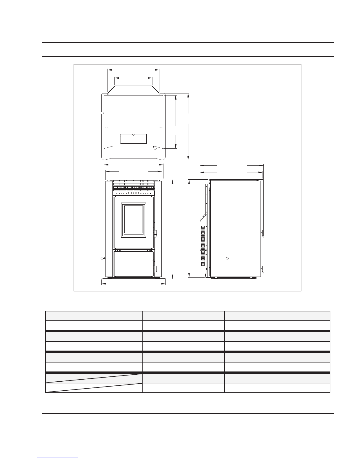
dimenSionS & SpecificationS:
3
21
/4" (553mm)
7
/8" (403mm)
15
Specifications
1
/4"
28
(716mm)
3
22
/8"
(568mm)
25" (637mm)
3
/4" (605mm)
23
27" (687mm)
7
/8"
41
(1063mm)
1
/4"
41
(1048mm)
3
/4" (680mm)
26
3
26
/8" (671mm)
Figure 1: Dimensions of Maxx.
Table 1: Maxx Specifications.
Testing Standard Frequency Voltage
ASTM 1509-04 60 Hz 110 - 120 V
Fuel type Current Max Power
wood pellets - 6mm (¼”) dia. 3.6 Amps 432 Watts
Description Hopper Capacity Consumption on Low
Residential Wood Pellet Heater up to 130 lb (59 Kg) 1.7 lb/hr (0.77 Kg/hr)*
*Note: Consumption will vary with the type of fuel used.
rating label location:
The rating label is located on the inside of the hopper lid.
Weight (with full hopper) Consumption on High
455 lb (206 Kg) 7.6 - 8.3 lb/hr (3.45-3.76 Kg/hr)*
5
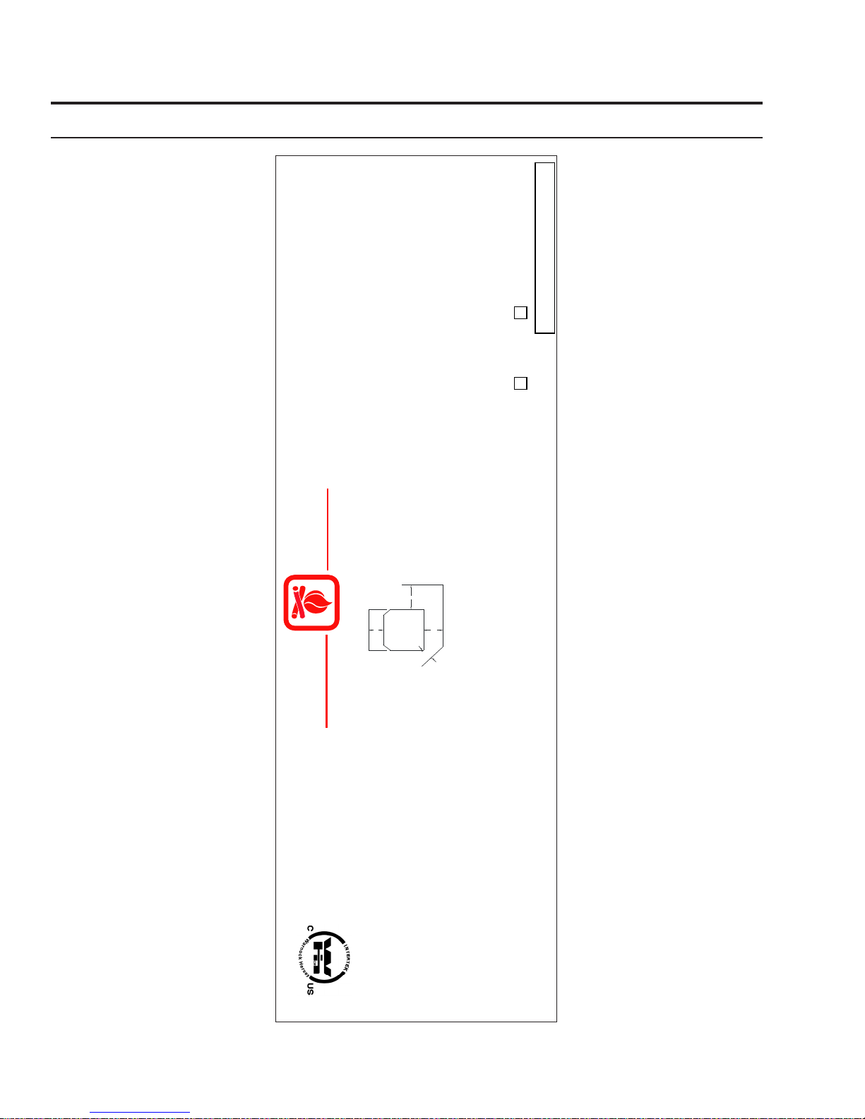
rating label:
Specifications
listed
Only replace glass with ceramic glass. Components required for installation 3in/75mm or 4in/100mm
seulement selon les instructions d'installation et d'opération du fabricant. Contactez les autorités
"Règles Administratives de l'Oregon 814-23-900 à 814-23-909". Installez et utilisez cet appareil
porte du réceptacle de cendre sont f ermées. S i une ou des vitres devaient être
remplacées, utilisez seulement du verre céramique. Les composantes requises pour
l'installation sont un évent PL certifié de 3in/75mm or 4in/100mm avec ses composantes.
J F M A M J J A S O N D 2008 2009 2010
locales de votre quartier concernant les restrictions et les inspectio
Cet appareil a été testé et certifié pour utilisation dans les maisons mobiles en accord avec les
codes de bâtiment locaux et les instructions du fabricant pour les précautions à prendre lorsque une
cheminée doit être insta llée au tr avers un m ur ou un plafon d combustible. CLASSEMENT
ÉLECTRIQUE : 120 Volts, 60 Hz, 3.1-3.6 Amps. Placez le câble électrique loin de la chaleur.
Utilisation avec granules seulement. Utiliser seul
PL vent complete with components.
DATE OF MANUFACTURE /
DATE DE FABRICATION:
ement lorsque les portes avants et la
the manufacturer's installation and operating instructions. Contact local building or fire officials about
3.1-3.6 Amps. Route Cord Away From Heater.
For use with pelletized solid fuels only. Operate only with viewing door and ash removal door closed.
Oregon Administrative rules 814-23-900 through 814-23-909.Install and use only in accordance with
another appliance. See local building code and m
for passing a chimney through a combustible wall or ceiling. ELECTRICAL RATING: 120 Volts, 60Hz,
restrictions and installation inspection in your area. Do not connect this unit to a chimney flue serving
Model / Modèle: ENVIRO
Listed Room Heater, Pelletized Fuel Type (Appareil de chauffage à granules certifié)
Report #310-1122 (January 2007) Tested to (Test
This pellet appliance has been tested and listed for use in manufactured homes in accordance with
Suitable For Mobile Home Installation (Accepté pour l'installation dans une maison mobile, test)
Serial No. / No. De Serié:
MAXX VF 170
anufacturer's instructions for precautions required
WH-
DO NOT REMOVE THIS LABEL /
ns d'installation. Consultez les
HOT WHILE IN OPERATION. DO NOT
CONTACT MAY CAUSE BURNS. SEE
CLOTHING AND FURNITURE AWAY.
NAMEPLATE AND INSTRUCTIONS.
surface. the unit m ust b e
The unit can be installed on a
hard, stabl e comb ustible
level ing legs and f loor
installed usin g the provided
protector. L'unité peu t être
instal lée su r un du r, la
surface combust ible s table
l'unité doit ê tre installée en
utilisa nt les jambe s et le
fournis de plancher.
TOUCH. KEEP CHILDREN,
TOUCHER. GARDER LES ENFANTS, LES VÊTEMENTS ET LES
MEUBLES ÉLOIGNÉS DE L'APPAREIL EN MARCHE. UN CONTACT
AVEC CELUI-CI POURRAIT RÉSULTER EN DES BRÛLURES.
VEUILLEZ VOIR LA PLAQUE DU FABRICANT ET LES INSTRUCTIONS.
L'APPAREIL EST CHAUD LORSQU'IL FONCTIONNE. NE PAS
protecteur de mise à niveau
CAUTION:
Sidewall
A
Floor Protection
ATTENTION:
D
contacts du thermostat sont fermés pendant ces 30 minutes, le réglage de niveau de chaleur retournera en
"AUTO/OFF" : (Nécessite un thermostat) Lorsque les contacts du thermostat ferment, le poêle s'allumera
réglages "MANUEL" ou si les contacts du thermostat restent ouverts, le poêle entamera le processus d'arrêt.
Pour éteindre le poêle : MODE MANUEL ET " HIGH/LOW " : Appuyer sur le bouton "ON/OFF".
MODE "AUTO / OFF" : Régler le thermostat
automatiquement. Lorsque la température adéquate est atteinte, les réglages peuvent être ajustés. Lorsque
les contacts du thermostat ouvrent, le poêl
Backwall
B
C
bouton manuel d'alimentation du Auger jusqu'à ce que les granules se déversent dans le pot de combustion.
Pour faire fonctionner le poêle : MODE MANUEL : Lorsque le feu est bien établi, les réglages peuvent être
ajustés. / MODE "HIGH/LOW" : (Nécessite un thermostat) Lorsque le thermostat requière de la chaleur, les
réglages peuvent être ajustés. Lorsque les contacts du thermostat ouvrent,
les ventilateurs s'ajusteront au réglage " bas " jusqu'à ce que les contacts du thermostat se referment. / MODE
é
e selon): ASTM 1509-04
Material / Espace de dégagement requis pour le modèle FS,
qu'il soit encastré, sur pied ou dans une maison mobile:
Sidewall to Unit / Du mur de côté à l'appareil:
A 12 in. / 300 mm
Backwall to Unit / Du mur de derrière à l'appareil:
Corner to Unit / Du coin à l'appareil:
C 4 in. / 100 mm
B 4 in. / 100 mm
the thermostat contacts close, the HEAT LEVEL will return to previous MANUAL setting or if the thermostat
contacts remain open the stove begin its shutdown routine.
To Turn Off Stove: MANUAL and HI / LOW mode: Press the ON / OFF button
AUTO / OFF mode: Turn the thermostat down or off.
Pour démarrer le poêle: Appuyer sur le bouton "ON/OFF". Si le Auger nécessite d'être amorcé, appuyer
Installed as a freestanding stove - conventional or mobile
home - Model FS. Min imum Clearances to Combustible
NE RETIREZ PAS CETTE ÉTIQUETTE
adjustable. When th
the thermostat contacts open, the stove will drop down to the LOW settings for 30 minutes. If wi
until the thermostat contacts close again. / AUTO/OFF MODE: (Requires a thermostat) When the thermostat
contacts close, the unit will light automatically. Once up to temperature the stove settings are adjustable. When
button until fuel starts to drop into the Burn Pot.
To Operate Stove: MANUAL MODE: When a fire has been established the stove settings are adjustable. /
To Start Stove: Press the ON / OFF button. If the auger needs to be primed, press the Manual Auger Feed
HIGH/LOW MODE: (Requires a therm ostat) When the thermostat call s for heat the stove settings are
e thermostat contacts open, the HEAT LEVEL and Fans will drop down to the LOW setting
Certified for use in Canada & USA
Certifié pour installation au
Canada et aux Etats-Unis.
6
à la baisse ou éteignez le.
e s'ajustera aux réglages "LOW" pendant 30 minutes. Si les
SHERWOOD INDUSTRIES
MANUFACTURED BY /
LTD. VICTORIA BC
FABRIQUE PAR
CANADA
:
le réglage du niveau de chaleur et
thin the 30 min
C-11580
sur le
Figure 2: Rating Label
Installation
deciding Where to locate your pellet appliance:
1. Do not install the stove in a bedroom or room where people sleep in.
2. Locate the stove in a large and open room that is centrally located in the house. This will optimize
heat circulation.
3. Check clearances to combustibles and for the least amount of interference to house framing, plumbing,
wiring, etc.
4. You can vent the stove with approved pipe through an exterior wall behind the unit or pass it through
the ceiling and roof. The stove can connect to an existing masonry or metal chimney (must be lined
if the chimney is over 6” (15 cm) diameter, or over 28 inches² (180 cm²) cross sectional area).
5. This unit must not be installed directly onto carpet. If it is to be installed on a carpeted area, a solid
surface (wood, metal or approved hearth pad) must be installed between the unit and the carpet.
6. This unit uses large quantities of air for combustion; outside Fresh Air connection is strongly
recommended. Fresh Air must be connected to all units installed in Mobile and “Air Tight Homes”
(R2000) or where required by local codes.
7. Do not obtain combustion air from an attic, garage or any unventilated space. Combustion air may be
obtained from a ventilated crawlspace.
8. The power cord is 8 feet (2.43 m) long and may require a grounded extension cord to reach the
nearest electrical outlet.
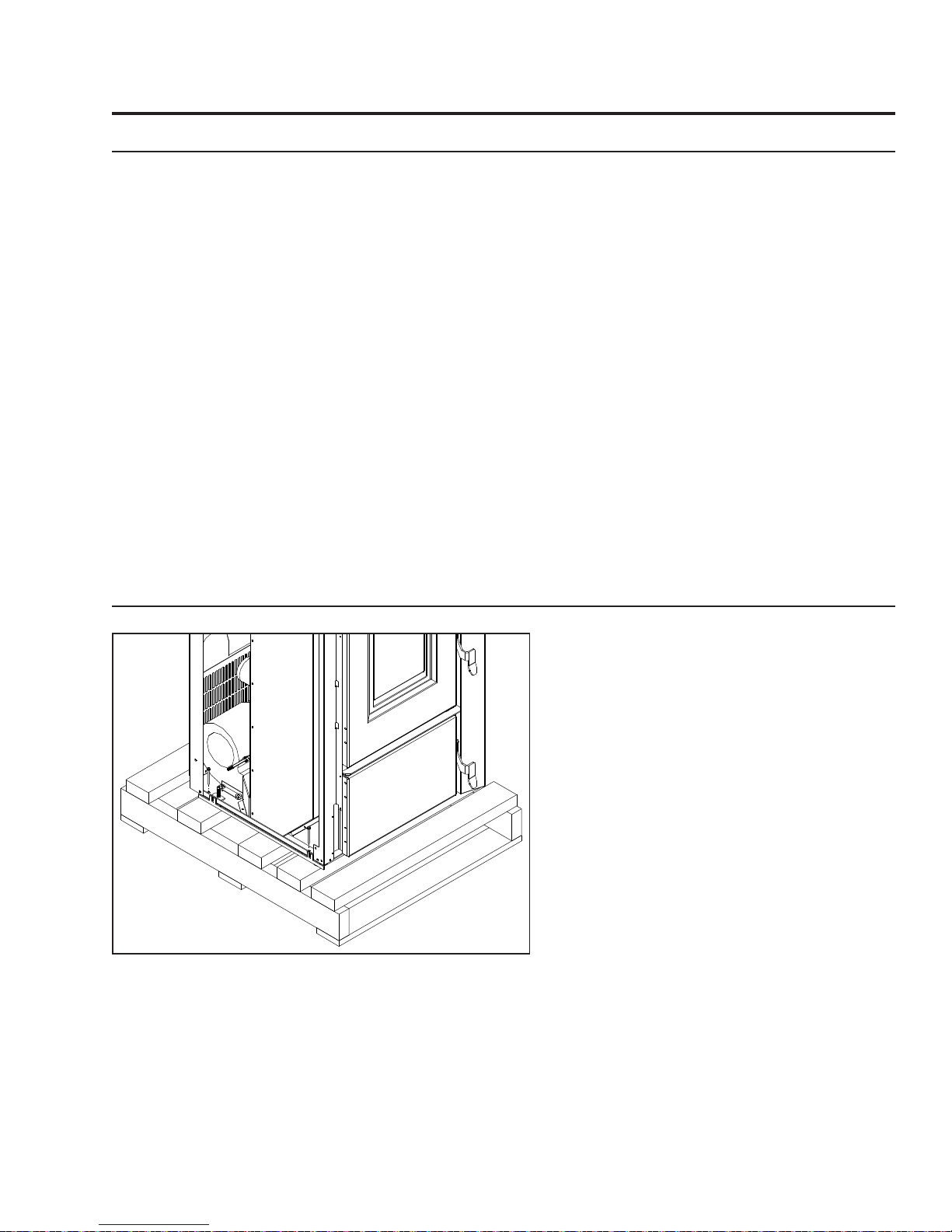
removing pellet Stove from pallet:
Figure 3: Screws to take out to remove stove from pallet.
1. Remove the right and left hand cabinet
sides. Partially back out the two (2) T-20
Torx screws on the back of the each panel
and the two (2) located on the front inside
edge below the louvers and ash shelf. Pull
the panel forward then remove.
2. Remove the two (2) wood screws from each
side that are holding the bottom of the
stove to the pallet.
3. Re-install the side panels.
7
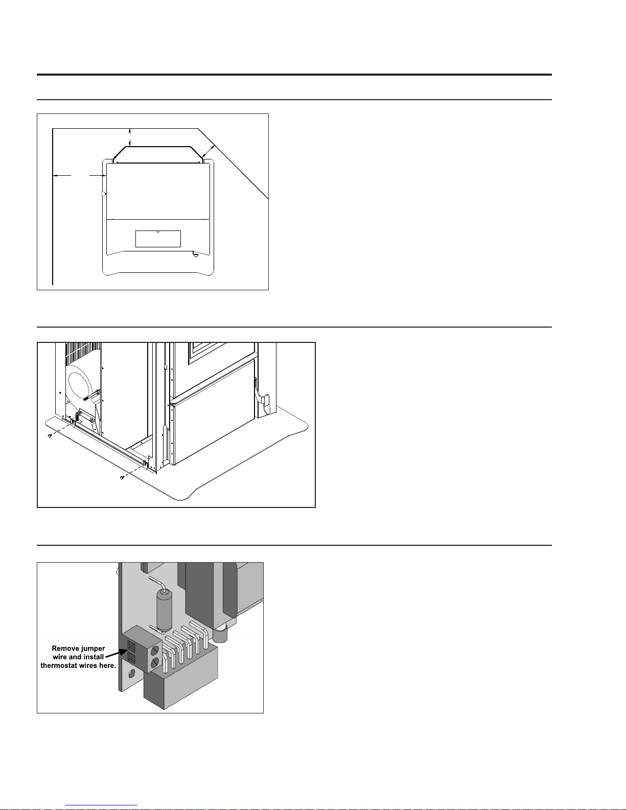
clearanceS to combuStibleS:
Remove jumper
wire and install
thermostat wires here.
Back Wall
4" (10cm)
12"
(30.5cm)
Side Wall
Figure 4: VF170 Clearance to Combustibles.
hearth Shield inStallation:
Installation
4"
(10cm)
Adjacent Wall
These dimensions are minimum clearances but it is
recommended that you ensure sufficient room for
servicing, routine cleaning and maintenance.
Side wall to unit 12 inches (30.5 cm)
Back wall to unit 4 inches (10 cm)
Corner to unit 4 inches (10 cm)
Ceiling height 90 inches (228.5 cm)
1. Remove the right and left hand cabinet
sides. Partially back out the two (2) T-20
Torx screws on the back of the each panel
and the two (2) located on the front inside
edge below the louvers and ash shelf. Pull
the panel forward then remove.
Figure 5: VF170 Hearth Shield Installation.
thermoStat inStallation:
Figure 6: Thermostat wire placement.
2. Slide the hearth shield into place.
3. Secure the shield to the unit with two (2)
screws on each side (see Figure 4).
4. Re-install the side panels.
1. Install the wall thermostat (12 or 24 Volt rated) in
a location that is not to close too the unit but will
effectively heat the desired area.
2. Connect the Thermostat or Timer using a 2 x 18 gauge
wire from the unit to the thermostat.
If the heat in the room becomes to great, the high limit
switch may turn the stove off and the switch will have to
be manually reset. To reset the high limit switch, remove
the right cabinet side. The switch is found on the air
jacket.
8
Installation
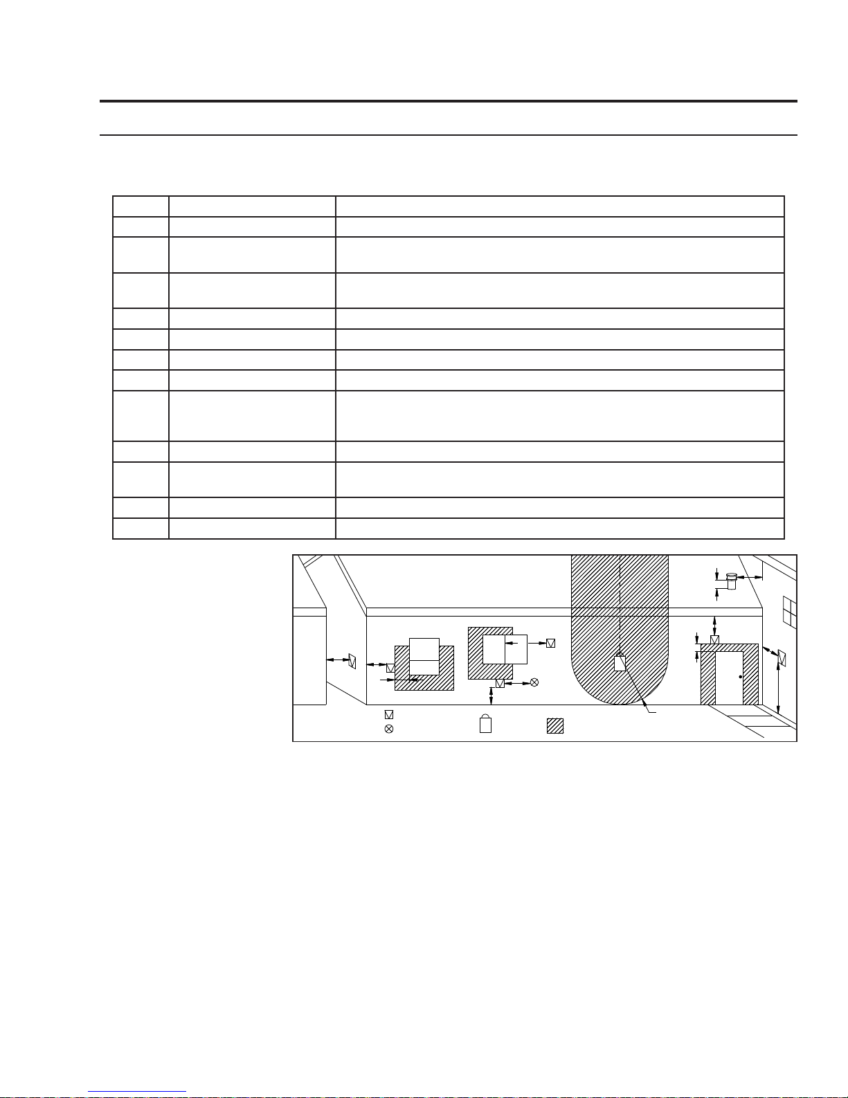
vent termination requirementS:
IT IS RECOMMENDED THAT YOUR PELLET STOVE BE INSTALLED BY AN AUTHORIZED DEALER/INSTALLER.
Table 2: Use in conjunction with Figure 7 for allowable exterior vent termination locations.
Letter Minimum Clearance Description
A 24 in (61 cm) Above grass, top of plants, wood, or any other combustible materials.
B 48 in (122 cm) Beside/below any door or window that may be opened. (18” (46 cm) if outside
fresh air installed.)
C 12 in (30 cm) Above any door or window that may be opened. (9” (23 cm) if outside fresh air
installed.)
D 24 in (61 cm) To any adjacent building, fences and protruding parts of the structure.
E 24 in (61 cm) Below any eave or roof overhang
F 12 in (30 cm) To outside corner.
G 12 in (30 cm) To inside corner, combustible wall (vertical and horizontal terminations).
H 3 ft (91 cm) within a height
of 15 ft (4.5 m) above the
meter/regulator assembly
I 3 ft (91 cm) From any forced air intake of other appliance
J 12 in (30 cm) Clearance to non-mechanical air supply inlet to building, or the combustion air
K 24 in (61 cm) Clearance above roof line for vertical terminations.
L 7 ft (2.13 m) Clearance above paved sidewalk or paved driveway located on public property.
To each side of center line extended above natural gas or propane meter/
regulator assembly or mechanical vent.
inlet to any appliance.
1. Do not terminate the
vent in any enclosed or
G
K
semi-enclosed areas such
as a carport, garage,
attic, crawlspace, narrow
walkway, closely fenced
area, under a sundeck
or porch, or any location
that can build up a
concentration of fumes
such as stairwells, covered
breezeway, etc.
2. Vent surfaces can become
B
D
F
Figure 7: Use in conjunction with Table 2 for allowable exterior vent termination
Opens
B
Termination Cap
Air Supply Inlet
Opens
A
G
I
Gas Meter
locations.
G
Restriction Zone
(Termination not allowed)
H
E
C
Opens
G
L
hot enough to cause burns if touched by children. Non-combustible shielding or guards may be required.
3. Termination must exhaust above the inlet elevation. It is recommended that at least five feet of vertical pipe be
installed outside when the appliance is vented directly through a wall, to create some natural draft to prevent the
possibility of smoke or odor during appliance shut down or power failure. This will keep exhaust from causing a
nuisance or hazard from exposing people or shrubs to high temperatures. In any case, the safest and preferred
venting method is to extend the vent through the roof vertically.
4. Distance from the bottom of the termination and grade is 12” (30 cm) minimum. This is conditional upon the
plants and nature of grade surface. The exhaust gases are hot enough to ignite grass, plants and shrubs located
in the vicinity of termination. The grade surface must not be lawn.
5. If the unit is incorrectly vented or the air to fuel mixture is out of balance, a slight discoloration of the exterior
of the house might occur. Since these factors are beyond the control of Sherwood Industries Ltd, we grant no
guarantee against such incidents.
NOTE: Venting terminals shall not be recessed into walls or siding.
9
 Loading...