

Vistaflame VF 170 Technical Manual
H E A R T H P R O D U C T S
SHERWOOD INDUSTRIES IS AN ENVIRONMENTALLY RESPONSIBLE COMPANY. THIS MANUAL IS PRINTED ON RECYCLED
PLEASE KEEP THESE INSTRUCTIONS FOR FUTURE REFERENCE.
PAPER.
VF 170
PELLET STOVE
TECHNICAL MANUAL
PLEASE READ THIS ENTIRE MANUAL BEFORE INSTALLATION
AND USE OF THIS PELLET-BURNING ROOM HEATER. FAILURE
TO FOLLOW THESE INSTRUCTIONS COULD RESULT IN
PROPERTY DAMAGE, BODILY INJURY OR EVEN DEATH.
Contact your building or fire officials about restrictions and installation
inspection requirements in your area.
50-1864

Table of Contents
Safety Warnings & Recommendations...............................................................................................3
Installation.....................................................................................................................................5
Rating Label Location................................................................................................................5
Deciding Where to Locate your Pellet Appliance..........................................................................5
Removing Pellet Stove From Pallet.............................................................................................5
Dimensions & Specifications......................................................................................................6
Clearances to Combustibles.......................................................................................................7
Hearth Shield Installation...........................................................................................................7
Thermostat Installation..............................................................................................................7
Vent Termination Requirements.................................................................................................8
Outside Fresh-Air Connection.....................................................................................................9
Exhaust And Fresh Air Intake Locations......................................................................................9
Mobile Home Installation.........................................................................................................10
Corner Through Wall Installation..............................................................................................10
Horizontal Exhaust Through Wall Installation............................................................................11
RECOMMENDED - Through Wall With Vertical Rise and Horizontal Termination Installation...........13
Through Concrete Wall With Vertical Rise Installations...............................................................13
Outside Vertical Installations....................................................................................................14
Inside Vertical Installations......................................................................................................15
Hearth Mount Installation........................................................................................................16
Slider/Damper Set-Up.............................................................................................................17
Troubleshooting............................................................................................................................18
Wiring Diagram.............................................................................................................................21
Parts List......................................................................................................................................22
Parts Diagram - Components.........................................................................................................24
Parts Diagram - Steel....................................................................................................................25
Warranty......................................................................................................................................26
Installation Data Sheet..................................................................................................................29
2

Safety Warnings & Recommendations
* This manual is designed for the technician in conjunction with the owner’s manual. *
Please read this entire Technical Manual before installing or operating your Vista Flame Pellet
Stove. Failure to follow these instructions may result in property damage, bodily injury or
even death. Any unauthorized modification of the appliance or use of replacement parts not
recommended by the manufacturer is prohibited. All national and local regulations and shall
be complied with when operating this appliance.
Caution: Do not connect to any air distribution duct or system.
Warning: Never place wood, paper, furniture, drapes or other combustible materials within 80cm (31”)
of the front of the unit, 30cm (12”) from each side, and 10cm (4”) from the back of the unit. Do not let
children or pets touch it when it is hot.
To prevent the possibility of a fire, ensure that the appliance is properly installed by adhering to the
installation instructions. An Vista Flame dealer will be happy to assist you in obtaining information with
regards to your local building codes and installation restrictions.
FIRE EXTINGUISHER AND SMOKE DETECTION: All homes with a pellet burning stove should have at
least one fire extinguisher in a central location known to all in the household. Smoke detectors should be
installed and maintained in the room containing the stove. If it sounds the alarm, correct the cause but do
not deactivate. You may choose to relocate the smoke detection devise within the room; DO NOT REMOVE
THE SMOKE DETECTOR FROM THE ROOM.
CHIMNEY OR RUN AWAY FIRE: Call local fire department (or dial 911). Close the draft fully. Extinguish
the fire in the burn pot liner with a cup of water and close the door. Examine the flue pipes, chimney, attic,
and roof of the house, to see if any part has become hot enough to catch fire. If necessary, spray with fire
extinguisher or water from the garden hose. IMPORTANT: Do not operate the stove again until you are
certain the chimney and its lining have not been damaged.
OPERATION: The door and ash drawer must be kept closed when the unit is in operation to prevent
fume spillage and for proper and safe operation of the pellet stove. Also ensure all gaskets on the door
are checked and replaced when necessary. Unit hot while in operation. Keep children, clothing and
furniture away. Contact may cause skin burns.
CAUTION: When operating during adverse weather, if the unit exhibits dramatic changes in combustion,
stop using the unit immediately.
FUEL: This pellet stove is designed and approved to only burn wood pellet fuel with up to 3% ash content.
Dirty fuel will adversely affect the operation and performance of the unit and may void the warranty. Check
with your dealer for fuel recommendations. THE USE OF CORDWOOD IS PROHIBITED BY LAW. Do
not burn garbage or flammable fluids such as gasoline, naptha or engine oil.
SOOT: Operation of the stove with insufficient combustion air will result in the formation of soot which will
collect on the glass, the heat exchanger, the exhaust vent system, and may stain the outside of the house.
This is a dangerous situation and is inefficient. Frequently check your stove and adjust the slider/damper
as needed to ensure proper combustion. See: “SLIDER/DAMPER SETTING”.
CLEANING: There will be some build up of fly ash and small amounts of creosote in the exhaust. This will
vary due to the ash content of the fuel used and the operation of the stove. It is advisable to inspect and
clean the exhaust vent semi-annually or every two tons of pellets.
The appliance, flue gas connector and the chimney flue require regular cleaning. Check them for blockage
prior to re-lighting after a prolonged shut down period.
ASHES: Disposed ashes should be placed in a metal container with a tight fitting lid. The closed container
of ashes should be on a non-combustible surface, well away from all combustible materials pending final
disposal. If the ashes are disposed of by burial in soil or otherwise locally dispensed, they should be retained
in the closed container until all cinders have thoroughly cooled.
3

Safety Warnings & Recommendations
ELECTRICAL: The use of a surge protected power bar is recommended. The unit must be grounded.
The grounded electrical cord should be connected to a standard 110-120 volts (3.6 Amps), 60 hertz electrical
outlet and also must be accessible. Ensure the polarity to the outlet, the unit will be plugged into, is correct as
incorrect polarity can affect the unit’s operation. If the power cord should become damaged, a replacement
power cord must be purchased from the manufacturer or a qualified Vista Flame dealer. Be careful that the
electrical cord is not trapped under the appliance and that it is clear of any hot surfaces or sharp edges. This
unit’s maximum power requirement is 432 watts.
When installing the stove in a mobile home, it must be electrically grounded to the steel chassis of the home
and bolted to the floor.
GLASS: Do not abuse the glass by striking or slamming the door. Do not attempt to operate the stove with
broken glass. The stove uses ceramic glass. Replacement glass must be purchased from an Vista Flame
dealer. Do not attempt to open the door and clean the glass while the unit is in operation or if glass is hot.
To clean the glass, use a soft cotton cloth and mild window cleaner, gas or wood stove glass cleaner, or take
a damp paper towel and dip into the fly ash. This is a very mild abrasive and will not damage the glass.
KEEP ASH PAN FREE OF RAW FUEL. DO NOT PLACE UNBURNED OR NEW PELLET FUEL IN ASH PAN. A
fire in the ash pan may occur.
INSTALLATION: Contact your local building or fire official to obtain a permit and any information on
installation restrictions and inspection requirements for your area.
Be sure to maintain the structural integrity of your home when passing a vent through walls, ceilings, or roofs,
and all construction meets local building codes. It is recommended that the unit be secured into its position
in order to avoid any displacement. This appliance must be installed on a floor with an adequate load bearing
capacity, if existing construction doesn’t meet load capacity, suitable measures (e.g. load distributing plate)
must be taken to achieve it.
DO NOT INSTALL A FLUE DAMPER IN THE EXHAUST VENTING SYSTEM OF THIS UNIT.
DO NOT CONNECT THIS UNIT TO A CHIMNEY FLUE SERVING ANOTHER APPLIANCE.
FRESH AIR: This unit uses large quantities of air for combustion; outside Fresh Air connection is strongly
recommended. Fresh Air must be connected to all units installed in Mobile and “Air Tight Homes” (R2000)
or where required by local codes.
Consider all large air moving devices when installing your unit and provide room air accordingly. NOTE:
Extractor fans when operating in the same room or space as the appliance may cause problems. Limited air
for combustion may result in poor performance, smoking and other side effects of poor combustion.
The stove’s exhaust system works with negative combustion chamber pressure and a slightly positive chimney
pressure. It is very important to ensure that the exhaust system be sealed and airtight. The ash pan and
viewing door must be locked securely for proper and safe operation of the pellet stove.
Do not burn with insufficient combustion air. A periodic check is recommended to ensure proper combustion
air is admitted to the combustion chamber. Setting the proper combustion air is achieved by adjusting the
slider damper located on the left side of the stove.
Minor soot or creosote may accumulate when the stove is operated under incorrect conditions such as an
extremely rich burn (black tipped, lazy orange flames).
If you have any questions with regards to your stove or the above-mentioned information, please feel free to
contact your local dealer for further clarification and comments.
SINCE SHERWOOD INDUSTRIES LTD. HAS NO CONTROL OVER THE INSTALLATION OF YOUR
STOVE, SHERWOOD INDUSTRIES LTD. GRANTS NO WARRANTY IMPLIED OR STATED FOR THE
INSTALLATION OR MAINTENANCE OF YOUR STOVE. THEREFORE, SHERWOOD INDUSTRIES
LTD. ASSUMES NO RESPONSIBILITY FOR ANY CONSEQUENTIAL DAMAGE(S).
SAVE THIS INSTRUCTION MANUAL FOR FUTURE REFERENCE.
4
Installation
RATING LABEL LOCATION:
The rating label is located on the inside of the hopper lid.
DECIDING WHERE TO LOCATE YOUR PELLET APPLIANCE:
1. Do not install the stove in a bedroom or room where people sleep in.
2. Locate the stove in a large and open room that is centrally located in the house. This will optimize
heat circulation.
3. Check clearances to combustibles and for the least amount of interference to house framing, plumbing,
wiring, etc.
4. You can vent the stove with approved pipe through an exterior wall behind the unit or pass it through
the ceiling and roof. The stove can connect to an existing masonry or metal chimney (must be lined
if the chimney is over 6” (15 cm) diameter, or over 28 inches² (180 cm²) cross sectional area).
5. This unit must not be installed directly onto carpet. If it is to be installed on a carpeted area, a solid
surface (wood, metal or approved hearth pad) must be installed between the unit and the carpet.
6. This unit uses large quantities of air for combustion; outside Fresh Air connection is strongly
recommended. Fresh Air must be connected to all units installed in Mobile and “Air Tight Homes”
(R2000) or where required by local codes.
7. Do not obtain combustion air from an attic, garage or any unventilated space. Combustion air may be
obtained from a ventilated crawlspace.
8. The power cord is 8 feet (2.43 m) long and may require a grounded extension cord to reach the
nearest electrical outlet.
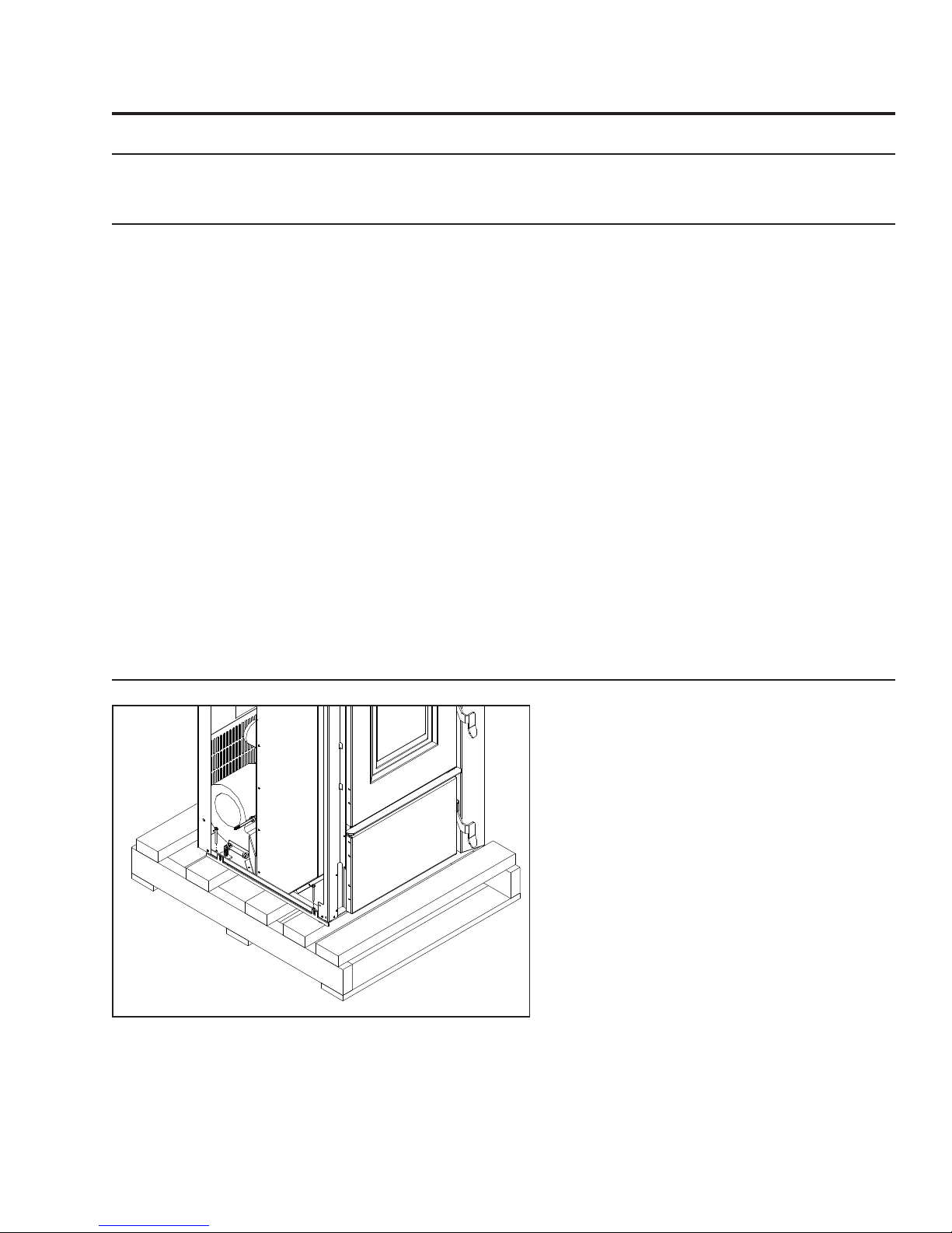
REMOVING PELLET STOVE FROM PALLET:
1. Remove the right and left hand cabinet
sides. Partially back out the two (2) T-20
Torx screws on the back of the each panel
and the two (2) located on the front inside
edge below the louvers and ash shelf. Pull
the panel forward then remove.
2. Remove the two (2) wood screws from each
side that are holding the bottom of the
stove to the pallet.
3. Re-install the side panels.
Figure 1: Screws to take out to remove stove from pallet.
5
22
3
/8"
(568mm)
28
1
/4"
(716mm)
26
3
/8" (671mm)
25" (637mm)
41
7
/8"
(1063mm)
15
7
/8" (403mm)
21
3
/4" (553mm)
26
3
/4" (680mm)
41
1
/4"
(1048mm)
23
3
/4" (605mm)
27" (687mm)
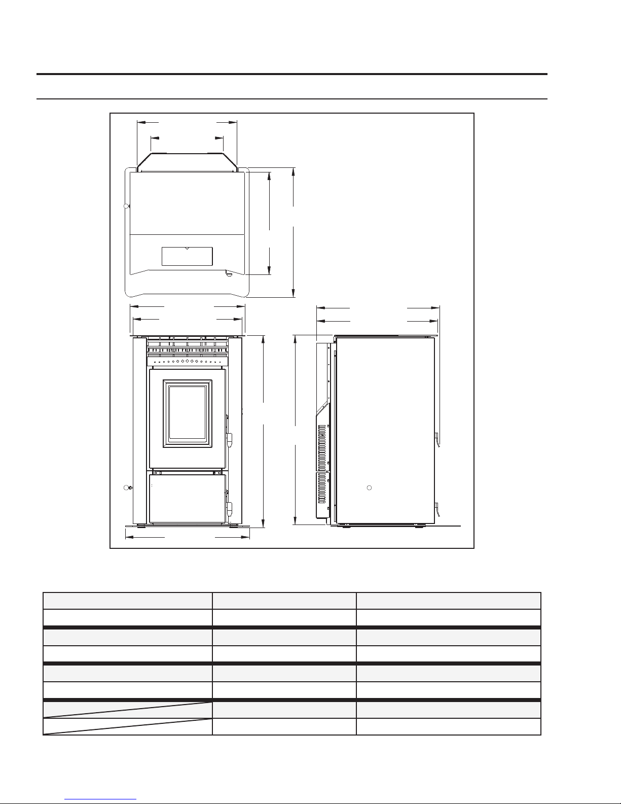
DIMENSIONS & SPECIFICATIONS:
Installation
Figure 2: Dimensions of VF170.
Table 1: VF170 Specifications.
Testing Standard Frequency Voltage
ASTM 1509-04 60 Hz 110 - 120 V
Fuel type Current Max Power
wood pellets - 6mm (”) dia. 3.6 Amps 432 Watts
Description Hopper Capacity Consumption on Low
Residential Wood Pellet Heater up to 130 lb (59 Kg) 1.7 lb/hr (0.77 Kg/hr)*
Weight (with full hopper) Consumption on High
455 lb (206 Kg) 7.6 - 8.3 lb/hr (3.45-3.76 Kg/hr)*
*Note: Consumption will vary with the type of fuel used.
6
CLEARANCES TO COMBUSTIBLES:
12"
(30.5cm)
4"
(10cm)
4" (10cm)
Side Wall
Back Wall
A
d
j
a
cent
W
a
l
l
Remove jumper
wire and install
thermostat wires here.
Figure 3: VF170 Clearance to Combustibles.
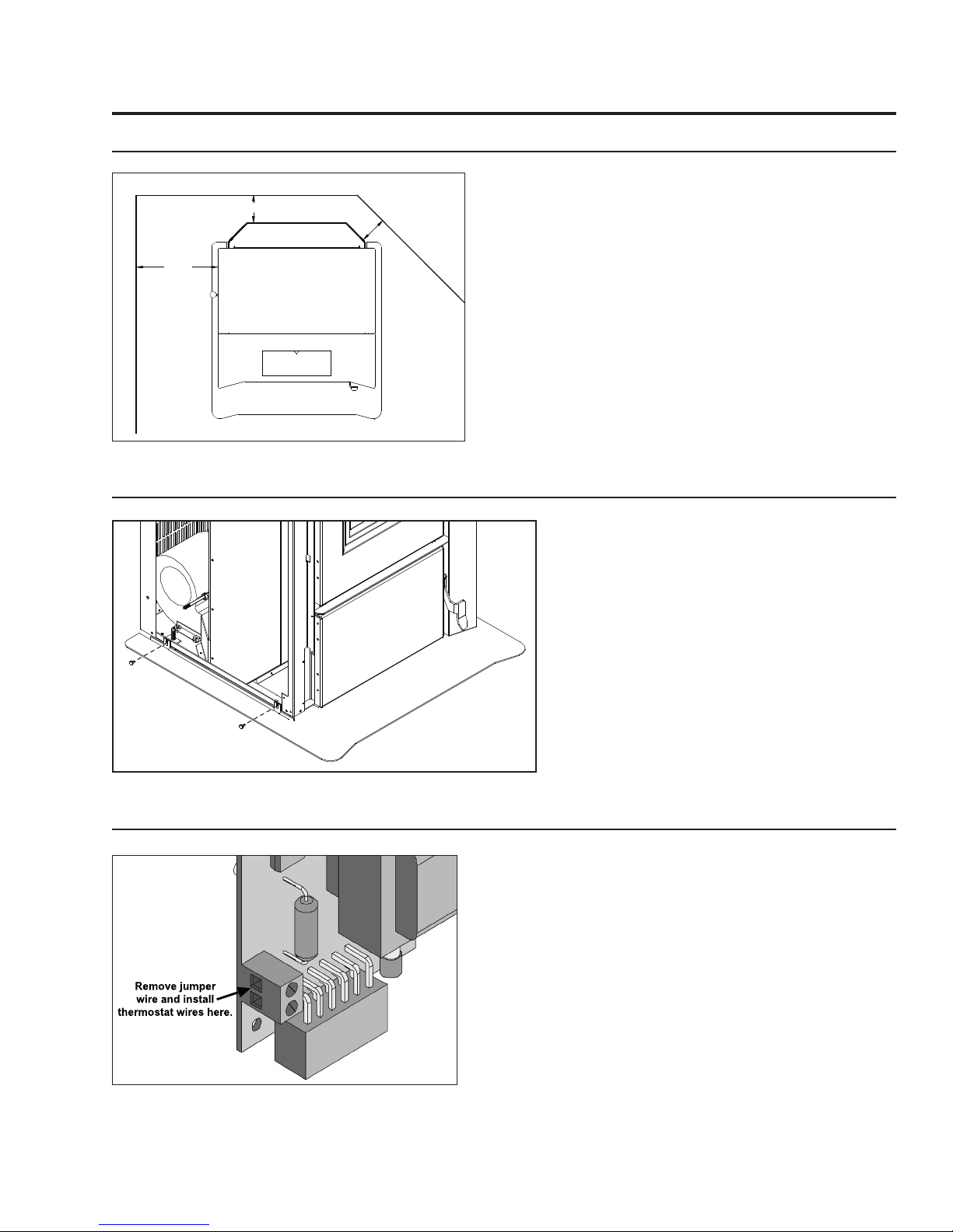
HEARTH SHIELD INSTALLATION:
Installation
These dimensions are minimum clearances but it is
recommended that you ensure sufficient room for
servicing, routine cleaning and maintenance.
Side wall to unit 12 inches (30.5 cm)
Back wall to unit 4 inches (10 cm)
Corner to unit 4 inches (10 cm)
Ceiling height 90 inches (228.5 cm)
1. Remove the right and left hand cabinet
sides. Partially back out the two (2) T-20
Torx screws on the back of the each panel
and the two (2) located on the front inside
edge below the louvers and ash shelf. Pull
the panel forward then remove.
Figure 4: VF170 Hearth Shield Installation.
THERMOSTAT INSTALLATION:
Figure 5: Thermostat wire placement.
2. Slide the hearth shield into place.
3. Secure the shield to the unit with two (2)
screws on each side (see Figure 4).
4. Re-install the side panels.
1. Install the wall thermostat (12 or 24 Volt rated) in
a location that is not to close too the unit but will
effectively heat the desired area.
2. Connect the Thermostat or Timer using a 2 x 18 gauge
wire from the unit to the thermostat.
If the heat in the room becomes to great, the high limit
switch may turn the stove off and the switch will have to
be manually reset. To reset the high limit switch, remove
the right cabinet side. The switch is found on the air
jacket.
7
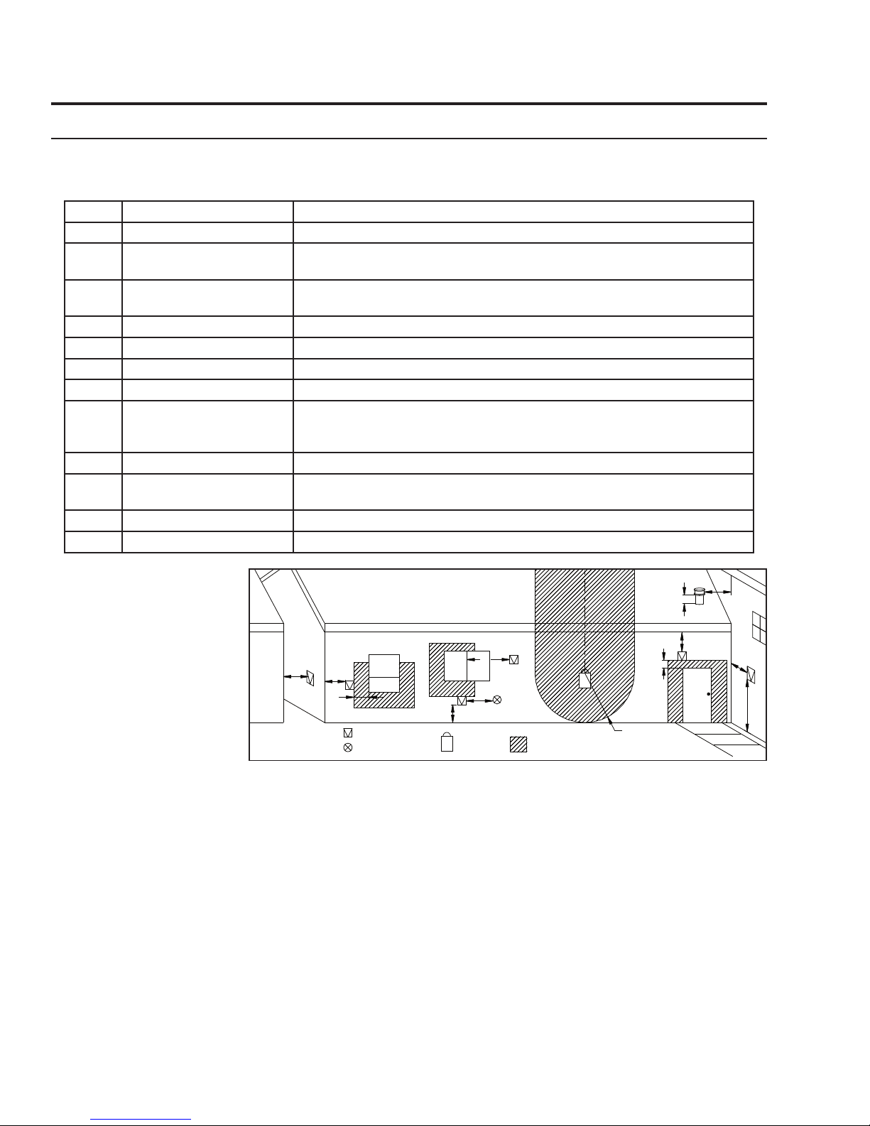
Installation
Air Supply Inlet
Gas Meter
Restriction Zone
(Termination not allowed)
Termination Cap
G
G
Opens
Opens
Opens
D
F
B
B
A
I
H
K
G
G
L
C
E
VENT TERMINATION REQUIREMENTS:
IT IS RECOMMENDED THAT YOUR PELLET STOVE BE INSTALLED BY AN AUTHORIZED DEALER/INSTALLER.
Table 2: Use in conjunction with Figure 6 for allowable exterior vent termination locations.
Letter Minimum Clearance Description
A 24 in (61 cm) Above grass, top of plants, wood, or any other combustible materials.
B 48 in (122 cm) Beside/below any door or window that may be opened. (18” (46 cm) if outside
fresh air installed.)
C 12 in (30 cm) Above any door or window that may be opened. (9” (23 cm) if outside fresh air
installed.)
D 24 in (61 cm) To any adjacent building, fences and protruding parts of the structure.
E 24 in (61 cm) Below any eave or roof overhang
F 12 in (30 cm) To outside corner.
G 12 in (30 cm) To inside corner, combustible wall (vertical and horizontal terminations).
H 3 ft (91 cm) within a height
of 15 ft (4.5 m) above the
meter/regulator assembly
I 3 ft (91 cm) From any forced air intake of other appliance
J 12 in (30 cm) Clearance to non-mechanical air supply inlet to building, or the combustion air
K 24 in (61 cm) Clearance above roof line for vertical terminations.
L 7 ft (2.13 m) Clearance above paved sidewalk or paved driveway located on public property.
To each side of center line extended above natural gas or propane meter/
regulator assembly or mechanical vent.
inlet to any appliance.
1. Do not terminate the
vent in any enclosed or
semi-enclosed areas such
as a carport, garage,
attic, crawlspace, narrow
walkway, closely fenced
area, under a sundeck
or porch, or any location
that can build up a
concentration of fumes
such as stairwells, covered
breezeway, etc.
Figure 6: Use in conjunction with Table 2 for allowable exterior vent termination
2. Vent surfaces can become
hot enough to cause burns if touched by children. Non-combustible shielding or guards may be required.
3. Termination must exhaust above the inlet elevation. It is recommended that at least five feet of vertical pipe be
installed outside when the appliance is vented directly through a wall, to create some natural draft to prevent the
possibility of smoke or odor during appliance shut down or power failure. This will keep exhaust from causing a
nuisance or hazard from exposing people or shrubs to high temperatures. In any case, the safest and preferred
venting method is to extend the vent through the roof vertically.
4. Distance from the bottom of the termination and grade is 12” (30 cm) minimum. This is conditional upon the
plants and nature of grade surface. The exhaust gases are hot enough to ignite grass, plants and shrubs located
in the vicinity of termination. The grade surface must not be lawn.
5. If the unit is incorrectly vented or the air to fuel mixture is out of balance, a slight discoloration of the exterior
of the house might occur. Since these factors are beyond the control of Sherwood Industries Ltd, we grant no
guarantee against such incidents.
NOTE: Venting terminals shall not be recessed into walls or siding.
8
locations.
Installation
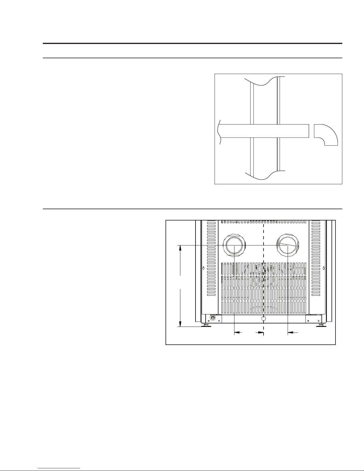
143/16"
(361mm)
51/8"
(130mm)
43/16"
(107mm)
OUTSIDE FRESH-AIR CONNECTION:
This Heater must have adequate air for proper combustion in the room that it is installed.
A Fresh-air intake is strongly recommended for all
installations. Failure to install intake air may result in
improper combustion as well as the unit smoking during
power failures.
The inlet to the intake must be below and a minimum of
12” (30cm) away from the unit exhaust outlet.
Outside fresh air is mandatory when installing this
unit in airtight homes and mobile homes.
When connecting to an outside fresh air source, do not
use plastic or combustible pipe. A 3” minimum (76 mm)
ID (inside diameter) steel, aluminum or copper pipe or
ducting should be used. It is recommended, when you are
installing a fresh air system, to keep the number of bends
in the pipe to a minimum.
EXHAUST AND FRESH AIR INTAKE LOCATIONS:
Figure 7: Outside Air Connection.
EXHAUST:
Base of unit to center of flue
min. 14
3
/
16” (361 mm)
Center of unit to center of flue
4
3
/
16” (107 mm)
FRESH AIR INTAKE.
Base of unit to center of intake
min. 14
3
/
16” (361 mm)
Center of unit to center of intake
5” (130 mm)
Figure 8: VF170 Inlet and Outlet Location.
9
 Loading...