

Vistaflame VF 100A Owner's Manual
SHERWOOD INDUSTRIES IS AN ENVIRONMENTALLY RESPONSIBLE COMPANY. THIS MANUAL IS PRINTED ON RECYCLED
PLEASE KEEP THESE INSTRUCTIONS FOR FUTURE REFERENCE
PAPER.
PELLET STOVE
VF 100A
Freestanding & Fireplace Insert
OWNER’S MANUAL
Contact your building or fire officials about restrictions and
installation inspection requirements in your area.
PLEASE READ THIS ENTIRE MANUAL BEFORE INSTALLATION AND
USE OF THIS PELLET BURNING ROOM HEATER. FAILURE TO FOLLOW
THESE INSTRUCTIONS COULD RESULT IN PROPERTY DAMAGE, BODILY
INJURY, OR EVEN DEATH.
VF-50279

Table of Contents
Introduction..............................................................................................................................3
Rating Label Location......................................................................................................3
Pellet Quality..................................................................................................................3
Important Safety Data....................................................................................................4
Safety Warnings And Recommendations...........................................................................4
Specifications...........................................................................................................................6
Dimensions - Freestanding..............................................................................................6
Dimensions - Insert........................................................................................................6
Operating Instructions...............................................................................................................7
Control Board Functions..................................................................................................7
Operating Your Pellet Stove.............................................................................................7
Turning Your Pellet Stove Off...........................................................................................8
Slider/Damper Set-Up.....................................................................................................8
Guidelines For Fine-Tuning For Fuel Quality.......................................................................9
Routine Cleaning and Maintenance...........................................................................................10
Installation.............................................................................................................................13
Deciding Where to Locate your Pellet Appliance..............................................................13
Automatic Safety Features of Your Pellet Stove................................................................13
Removing Pellet Stove From Pallet.................................................................................13
Installation Of Pedestal - Insert......................................................................................14
Clearances to Combustibles - Freestanding.....................................................................15
Clearances to Combustibles - Insert...............................................................................15
Clearances to Alcove - Freestanding...............................................................................15
Outside Fresh-Air Connection.........................................................................................16
Exhaust And Fresh Air Intake Locations.........................................................................16
Vent Termination Requirements.....................................................................................17
Mobile Home Installation - Freestanding.........................................................................18
Corner Through Wall Installation - Freestanding..............................................................18
Horizontal Exhaust Through Wall Installation - Freestanding............................................19
Through Wall With Vertical Rise and Horizontal Termination Installation - Freestanding......20
Inside Vertical Installations - Freestanding......................................................................21
Outside Vertical Installations - Freestanding....................................................................21
Hearth Mount Installation - Freestanding........................................................................22
Masonry Fireplace Installation - Fireplace Insert..............................................................23
Installation Into Factory Built Fireplaces.........................................................................25
Installation of Control Panel into Surround Panel - Insert.................................................25
Installation and Removal of The Surround Panels - Insert................................................26
Thermostat Installation.................................................................................................27
The Tube Scraper Rod...................................................................................................27
Slider/Damper Installation.............................................................................................27
Troubleshooting......................................................................................................................28
Wiring Diagram.......................................................................................................................31
Parts List................................................................................................................................32
Parts Diagram - Components....................................................................................................35
Parts Diagram - Steel...............................................................................................................36
Warranty.................................................................................................................................37
Installation Data Sheet............................................................................................................40
2

Introduction
RATING LABEL LOCATION:
Freestanding: The rating label is located on the inside of the hopper lid.
Insert: The rating label is located on the hopper cover.
PELLET QUALITY:
Pellet quality is important, please read the following:
Your Vista Flame pellet stove has been designed to burn wood pellets only. Do not use any
other type of fuel, as this will void any warranties stated in this manual.
The performance of your pellet stove is greatly affected by the type and quality of wood
pellets being burned. As the heat output of various quality wood pellets differs, so will the
performance and heat output of the pellet stove.
CAUTION: It is important to select and use only pellets that are dry and free of dirt or any impurities
such as high salt content. Dirty fuel will adversely affect the operation and performance of the unit
and will void the warranty. The Pellet Fuel Industries (P.F.I.) has established standards for wood pellet
manufacturers. We recommend the use of pellets that meet or exceed these standards. Ask your dealer
for a recommended pellet type.
P.F.I. PELLET STANDARDS:
Fines (fine particles)......1% maximum through a ” screen
Bulk Density..................40 pound per cubic foot minimum
Size..............................” to
Ash Content..................1% maximum (Premium grade)
..................3% maximum (Standard grade)
Moisture Content...........8% maximum
Heat Content.................approximately 8200 Btu per pound minimum
ASH: The ash content of the fuel and operation of your stove will directly determine the frequency of
cleaning. The use of high ash fuels may result in the stove needing to be cleaned daily. A low ash fuel
may allow longer intervals between cleaning.
CLINKERING: [clinkers are silica (sand) or other impurities in the fuel that will form a hard mass
during the burning process]. This hard mass will block the air flow through the Burn Pot Liner and
affect the performance of the stove. Any fuel, even approved types, may tend to clinker. Check the
Burn-Pot Liner daily to ensure that the holes are not blocked with clinkers. If they become blocked,
remove the liner (when the unit is cold) and clean/scrape the clinkers out. Clean the holes with a small
pointed object if required. Refer to the section Routine Cleaning and Maintenance.
PELLET FEED RATES: Due to different fuel densities and sizes, pellet feed rates may vary. This may
require an adjustment to the slider damper setting or to the auger feed trim setting on low.
Since Sherwood Industries Ltd. has no control over the quality of pellets that you use, we assume no
liability for your choice in wood pellets.
5
/16” diameter – 1” long maximum
Store pellets at least 36” (1 m) away from the pellet stove.
3

Introduction
IMPORTANT SAFETY DATA:
Please read this entire Owner’s Manual before installing or operating your Vista Flame Pellet
Stove. Failure to follow these instructions may result in property damage, bodily injury or
even death. Contact your local building or fire official to obtain a permit and any information on
installation restrictions and inspection requirements for your area.
To prevent the possibility of a fire, ensure that the appliance is properly installed by adhering to the
installation instructions. An Vista Flame dealer will be happy to assist you in obtaining information with
regards to your local building codes and installation restrictions.
Be sure to maintain the structural integrity of the home when passing a vent through walls, ceilings, or
roofs.
The stove’s exhaust system works with negative combustion chamber pressure and a slightly positive
chimney pressure. It is very important to ensure that the exhaust system be sealed and airtight. The ash
pan and viewing door must be locked securely for proper and safe operation of the pellet stove.
Do not burn with insufficient combustion air. A periodic check is recommended to ensure proper
combustion air is admitted to the combustion chamber. Setting the proper combustion air is achieved by
adjusting the slider damper located on the left side of the stove.
When installing the stove in a mobile home, it must be electrically grounded to the steel chassis of the
home and bolted to the floor. Make sure that the structural integrity of the home is maintained and all
construction meets local building codes.
Minor soot or creosote may accumulate when the stove is operated under incorrect conditions such as an
extremely rich burn (black tipped, lazy orange flames).
SAFETY WARNINGS AND RECOMMENDATIONS:
Caution: Do not connect to any air distribution duct or system.
Do not burn garbage or flammable fluids such as gasoline, naptha or engine oil.
Unit hot while in operation. Keep children, clothing and furniture away. Contact
may cause skin burns.
FUEL: This pellet stove is designed and approved to only burn wood pellet fuel with up to 3% ash
content. Dirty fuel will adversely affect the operation and performance of the unit and may void the
warranty. Check with your dealer for fuel recommendations.
THE USE OF CORDWOOD IS PROHIBITED BY LAW.
SOOT: Operation of the stove with insufficient combustion air will result in the formation of soot which
will collect on the glass, the heat exchanger, the exhaust vent system, and may stain the outside of the
house. This is a dangerous situation and is inefficient. Frequently check your stove and adjust the slider/
damper as needed to ensure proper combustion. See: “S
CLEANING: There will be some build up of fly ash and small amounts of creosote in the exhaust. This
will vary due to the ash content of the fuel used and the operation of the stove. It is advisable to inspect
and clean the exhaust vent semi-annually or every two tons of pellets.
LIDER/DAMPER SETTING”.
ASHES: Disposed ashes should be placed in a metal container with a tight fitting lid. The closed container
of ashes should be on a non-combustible floor on the ground, well away from all combustible materials
pending final disposal. If the ashes are disposed of by burial in soil or otherwise locally dispensed, they
should be retained in the closed container until all cinders have been thoroughly cooled.
4

Introduction
ELECTRICAL: The use of a surge protected power bar is recommended. The unit must be
grounded. The grounded electrical cord should be connected to a standard 115 volts (4.5 Amps), 60 hertz
electrical outlet. Ensure the polarity to the outlet, the unit will be plugged into, is correct as incorrect
polarity can affect the unit’s operation. Be careful that the electrical cord is not trapped under the
appliance and that it is clear of any hot surfaces or sharp edges and also must be accessible. If this power
cord should become damaged, a replacement power cord must be purchased from the manufacture or a
qualified Vista Flame dealer. The VF100’s maximum power requirement is 520 watts.
GLASS: Do not abuse the glass by striking or slamming the door. Do not attempt to operate the stove
with broken glass. The stove uses ceramic glass. Replacement glass must be purchased from an Vista
Flame dealer. Do not attempt to open the door and clean the glass while the unit is in operation or if
glass is hot. To clean the glass, use a soft cotton cloth and mild window cleaner, gas or wood stove glass
cleaner, or take a damp paper towel and dip into the fly ash. This is a very mild abrasive and will not
damage the glass.
FLAMMABLE LIQUIDS: Never use gasoline, gasoline-type lantern fuel, kerosene, charcoal lighter
fluid, or similar liquids to start or “freshen up” a fire in the heater. Keep all such liquids well away from
the heater while it is in use.
SMOKE DETECTOR: Smoke detectors should be installed and maintained in the structure when
installing and operating a pellet burning appliance.
OPERATION: The ash pan and door must be closed securely for proper and safe operation of the pellet
stove. Also ensure all gaskets on the door are checked and replaced when necessary.
KEEP ASH PAN FREE OF RAW FUEL.
DO NOT PLACE UNBURNED OR NEW PELLET FUEL IN ASH PAN. A fire in the ash pan may occur.
INSTALLATION: Be sure to maintain the structural integrity of your home when passing a vent through
walls, ceilings, or roofs. It is recommended that the unit be secured into its position in order to avoid any
displacement.
DO NOT INSTALL A FLUE DAMPER IN THE EXHAUST VENTING SYSTEM OF THIS UNIT.
DO NOT CONNECT THIS UNIT TO A CHIMNEY FLUE SERVING ANOTHER APPLIANCE.
FRESH AIR: Outside Fresh Air connection is optional. Must be connected to all units installed in Mobile
and “Air Tight Homes” (R2000) or where required by local codes. Consider all large air moving devices
when installing your unit and provide room air accordingly. Limited air for combustion may result in poor
performance, smoking and other side effects of poor combustion.
If you have any questions with regards to your stove or the above-mentioned information, please feel
free to contact your local dealer for further clarification and comments.
SINCE SHERWOOD INDUSTRIES LTD. HAS NO CONTROL OVER THE INSTALLATION OF
YOUR STOVE, SHERWOOD INDUSTRIES LTD. GRANTS NO WARRANTY IMPLIED OR STATED
FOR THE INSTALLATION OR MAINTENANCE OF YOUR STOVE. THEREFORE, SHERWOOD
INDUSTRIES LTD. ASSUMES NO RESPONSIBILITY FOR ANY CONSEQUENTIAL DAMAGE(S).
SAVE THIS INSTRUCTION MANUAL FOR FUTURE REFERENCE
5
247/16"
(621mm)
243/8"
(620mm)
22"
(559mm)
34
1
/8"
(867mm)
23
3
/4"
(603mm)
Regular Panel 40" (1016mm)
Oversized Panel 46" (1158mm)
22
3
/4"
(579mm)
12
5
/8"
(322mm)
23
5
/8"
(601mm)
Regular Panel
30
1
/8" (766mm)
Oversized Panel
32
7
/8" (835mm)
22
3
/4"
(579mm)
22"
(559mm)
1
3
/8"
(34mm)
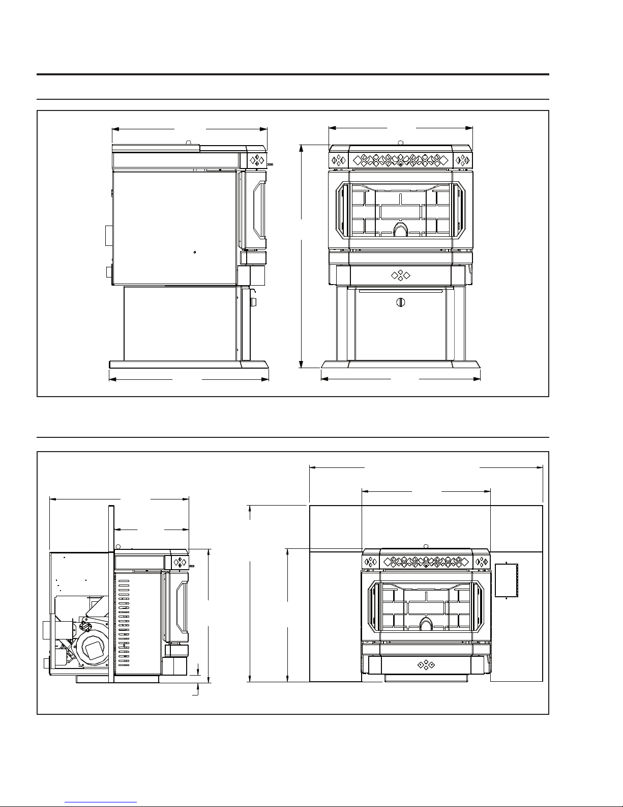
DIMENSIONS - FREESTANDING:
Specifications
DIMENSIONS - INSERT:
Figure 1: Dimensions of VF100 Freestanding.
6
Figure 2: Dimensions of VF100 Insert.
Operating Instructions
ROOM AIR
FAN ON/OFF
ON/OFF
FEED RATE
TRIM
COMBUSTION
BLOWER TRIM
HEAT LEVEL
AUTO/OFF
HIGH/LOW
MANUAL
AUGER
C-11625
MODE
ROOM AIR
FAN ON/OFF
ON/OFF
FEED RATE
TRIM
COMBUSTION
BLOWER TRIM
HEAT LEVEL
AUTO/OFF
HIGH/LOW
MANUAL
AUGER
C-11625
MODE
1
2
3
4
5
6
8
7
9
AUTO/OFF
HIGH/LOW
MANUAL
AUGER
MODE
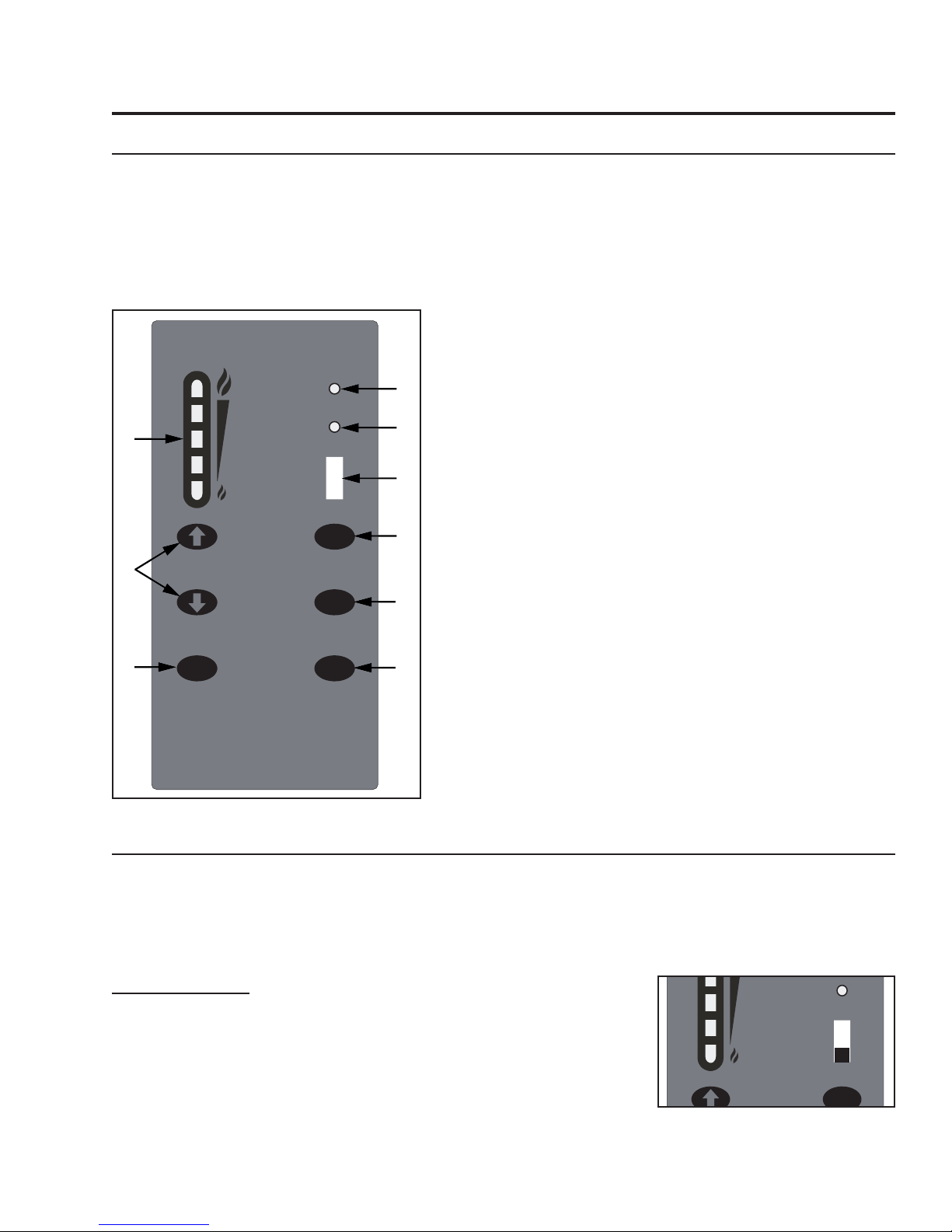
CONTROL BOARD FUNCTIONS:
1. AUGER LIGHT: This green light will flash in conjunction with the auger pulse.
2. MODE LIGHT: Responsible for signaling the state of the control board. When the light is flashing the
stove is in an automatic start mode or the thermostat has control of the unit. When the light is solid,
the Heat Level Setting can be altered.
3. THERMOSTAT SWITCH: Used to set the unit’s controls to one of three mode settings; manual,
high/low, or auto/off.
4. FEED RATE TRIM BUTTON: Used to change the feed rate
trims in second increments for all feed settings. When
this button is pressed, all the light will light up on the Heat
Output Indicator except for the one that shows the current
setting; the default setting is the number 4 light. To adjust
the setting hold the Feed Rate Trim button down and press
the Heat Level up or down buttons to adjust the setting.
5. COMBUSTION BLOWER TRIM BUTTON: Used to
change the Combustion Blower trims in 5 volt increments
for all feed settings until it reaches line voltage. When this
button is pressed, all the light will light up on the Heat
Output Indicator except for the one that shows the current
setting; the default setting is the number 2 light. To adjust
the setting hold the Combustion Blower Trim button down
and press the Heat Level up or down buttons to adjust the
setting.
6. ON/OFF BUTTON: Used to turn the unit ON and OFF.
7. ROOM AIR FAN ON/OFF BUTTON: Used to turn
convection fan on or off.
8. HEAT LEVEL ADJUSTMENT BUTTONS: When pressed,
will change the heat level setting of the unit up or down.
9. HEAT OUTPUT INDICATOR: Shows the present heat
output setting.
Figure 3: Circuit Board Control Panel Decal.
OPERATING YOUR PELLET STOVE:
PRE-BURN INSTRUCTIONS: The burn pot liner holes must be clear and the liner installed properly
against the ignitor tube for proper operation. Check the hopper for enough pellets to start the unit.
DO NOT OPERATE THE UNIT WITH THE DOOR OR ASH PAN OPEN.
Note: The thermostat mode can be changed during normal operation.
MANUAL MODE:
All control of circuit board function is adjusted at the circuit board.
To START: Press the ON / OFF button. The stove will turn on. The
system light will flash. The Auger Light will flash with each pulse of the
auger (the Auger Feed Rate is pre-programmed during start-up). The
Heat Level Indicator will show the Heat Level that the stove will run at
after start-up and can be adjusted but the change will not take affect
until the start -up has finished.
Figure 4: Thermostat Switch in
MANUAL position.
7
AUTO/OFF
HIGH/LOW
MANUAL
AUGER
MODE
AUTO/OFF
HIGH/LOW
MANUAL
AUGER
MODE
Operating Instructions
If this is the first time the unit has been started or the unit has run out of fuel, the auger will need to
be primed. This can be done by restarting the unit five (5) minutes into its start-up or by putting a small
hand full of pellets into the burnpot.
To OPERATE: When a fire has been established, the System Light will turn solid (after approximately 10
- 15 minutes) and the Auger Light will continue to flash to the corresponding Heat Level setting.
The convection blower (room air blower) will turn on. The speed of this blower is controlled by the setting
of the heat level output indicator. The convection blower can be turned OFF by depressing the convection
blower control button. For the best efficiency the convection blower should be left on at all times.
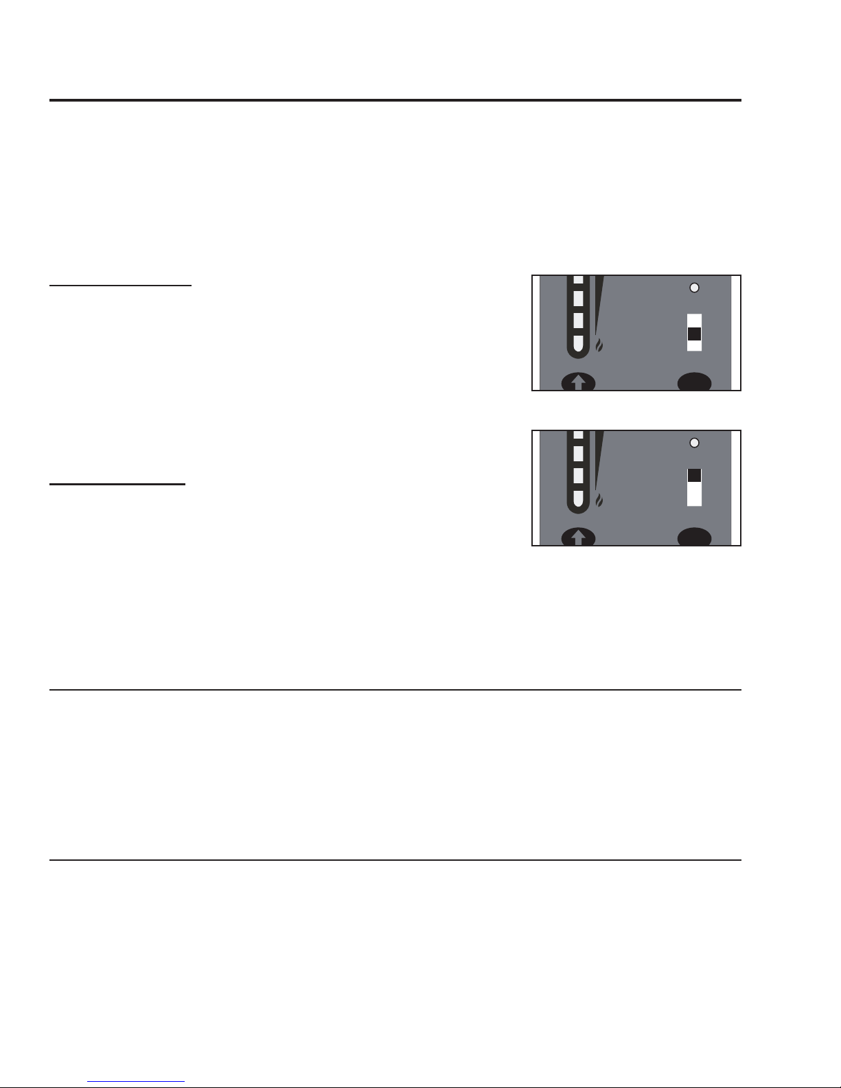
HIGH/LOW MODE: (Requires a thermostat)
INITIAL START-UP: See manual mode above.
OPERATION: When the thermostat calls for heat (contacts are closed)
the stove settings are adjustable as per Manual Mode. When the
thermostat contacts open, the HEAT LEVEL and Fans will drop down to
the LOW setting until the thermostat contacts close again. *The LOW
heat setting can be adjusted for different fuel qualities (see “O
INSTRUCTIONS - CONTROL BOARD FUNCTIONS”). The stove will come back to
the previous HEAT LEVEL setting when the thermostat contacts close
again.
PERATING
Figure 5: Thermostat Switch in
HIGH/LOW position.
AUTO/OFF MODE:
(Requires a thermostat)
INITIAL START-UP: See manual mode above.
OPERATION: When the thermostat contacts close, the unit will light
automatically. Once up to temperature, the stove operates the same
as in MANUAL. When the thermostat contacts open, the stove’s HEAT
LEVEL and Fans will drop down to the LOW setting for 30 minutes. If
Figure 6: Thermostat Switch in
ON/OFF position.
the thermostat contacts close within the 30 minutes, the HEAT LEVEL will return to the previous MANUAL
setting. If the thermostat contacts remain open the stove automatically begins its shutdown routine. The
ON / OFF button can be presses at any time the the stove will immediately shut down. The stove will relight when the thermostat contacts close again.
T
URNING YOUR PELLET STOVE OFF
:
• MANUAL and HI / LOW mode: To turn the unit OFF, simply press the ON / OFF button. This will stop
the feed of pellets. The blowers will continue to operate and cool the stove down. When cool enough,
the stove will turn off.
• AUTO / OFF mode: To turn the unit OFF, turn the thermostat down or off. NOTE: The unit will run on
low for three (3) minutes before it turns off.
DO NOT unplug unit while Combustion fan is operating.
This may lead to smoke escaping from the stove.
SLIDER/DAMPER SET-UP:
THE SLIDER / DAMPER MUST BE SET AT TIME OF INSTALLATION. A Qualified Service Technician
or Installer must set the Slider Damper.
If the fire should happen to go out and the heat output indicator has been set on the lowest setting, the
Slider Damper should be pushed in slightly, decreasing the air in the firebox.
If, after long periods of burning, the fire builds up and overflows the burn pot or there is a build up of
clinkers, this would be a sign that the pellet quality is poor, this requires more primary air, the slider
damper must be pulled out to compensate. Pulling the slider damper out gives the fire more air.
8
Operating Instructions
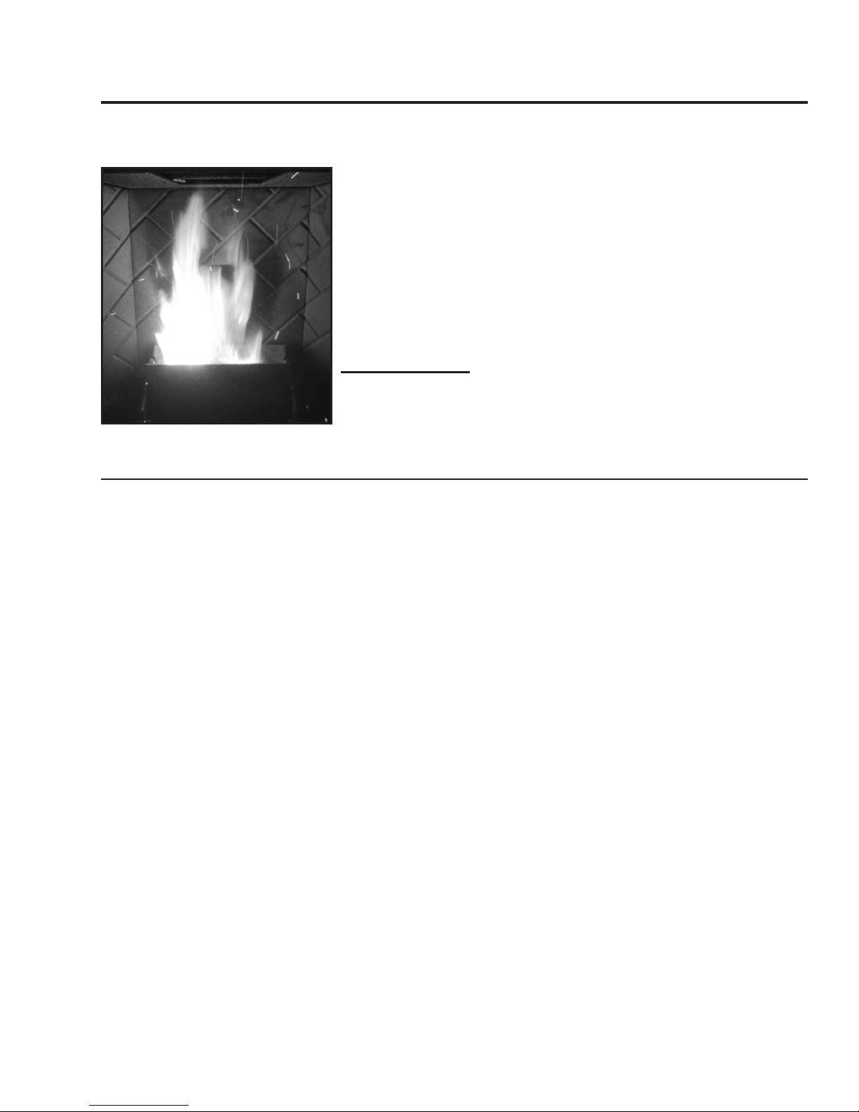
The easiest way to make sure that an efficient flame is achieved is to understand the characteristics of
the fire.
• A tall, lazy flame with dark orange tips requires more air – Open
slider (pull out) slightly.
• A short, brisk flame, like a blowtorch, has too much air – Close
slider (push in) slightly.
• If the flame is in the middle of these two characteristics with a
bright yellow/orange, active flame with no black tips then the air is
set for proper operation, refer to Figure 7.
The combustion exhaust blower is a variable speed blower controlled
by the heat output button. This blower will decrease the vacuum
pressure inside the stove, adjusting the air to fuel ratio.
SPECIAL NOTES:
Pellet quality is a major factor in how the Pellet stove will operate. If
the pellets have a high moisture content or ash content the fire will
Figure 7: Efficient Flame.
be less efficient and has a higher possibility of the fire building up and
creating clinkers (hard ash build-up).
GUIDELINES FOR FINE-TUNING FOR FUEL QUALITY:
Due to fuel quality the slider damper and control board trims may need to be fine-tuned.
1. If the unit builds up on all settings, the slider damper rod should be pulled out in small increments to
give the unit more air.
2. If the unit has excesses ash build-up in the liner on the lower feed settings, the Combustion Blower
Trim should be increased one setting at a time until the problem improves (Factory Setting is #2).
3. If the fire is going out on low because the airflow is too great, the Combustion Blower Trim can be
lowered to the #1 setting.
4. If the stove has excesses ash build-up in the liner on the higher settings the Feed Rate Trim should be
trimmed down a setting at a time until the problem improves (Factory setting is #4).
5. If you need more heat and the fuel has long pellets, the majority are over 1” (2.5cm) in length, the
Feed Rate Trim can be moved up to the #5 setting. NOTE: Only do this if the fuel burns without
building up.
9
Routine Cleaning and Maintenance
NOTE: Do not use abrasive cleaners to clean the surface or any part of the stove.
The following should be inspected periodically to ensure that the appliance is operating at its optimum
and giving you excellent heat value:
TOOLS REQUIRED TO CLEAN UNIT
2-3 Days / Weekly Bi-Annually or 2 Tons of Fuel
Burn Pot and Liner Exhaust Vent
Ash Pan Fresh air Intake Tube
Inside Firebox Blower Mechanisms
Door Glass Heat exchanger tubes
Heat exchanger tubes Behind firebox liners
Ash pan & Door gaskets All Hinges
Door Latch Post Season Clean-up
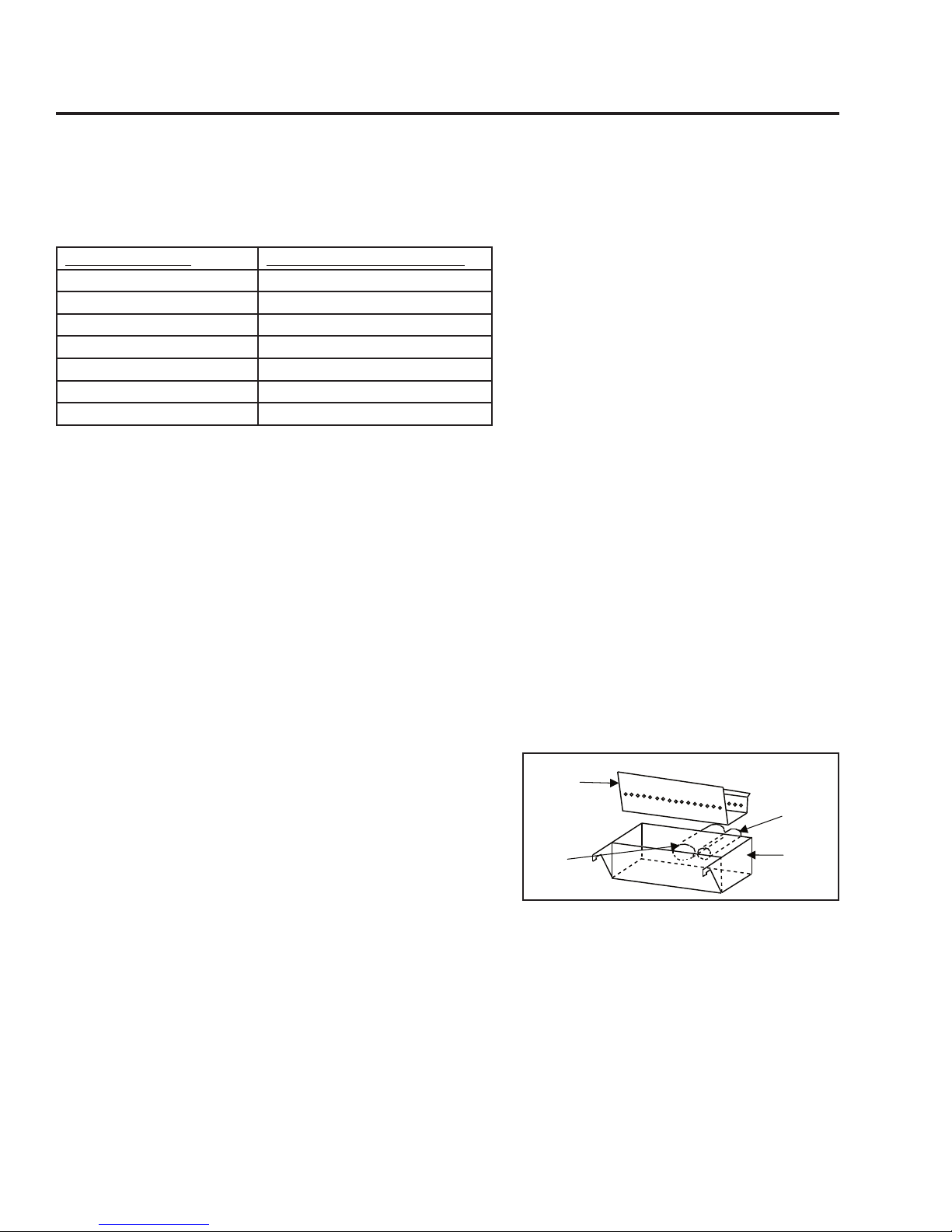
BURN POT AND LINER (2-3 days)
This is the ‘pot’ where the pellets are burned. The burn pot and liner should be inspected every two to
three (2-3) days, to ensure proper air flow through the liner. Failure to keep the liner clean may
cause a build up of fuel past the burn pot liner and up the drop tube. This will cause the
auger to jam and may result in pellets burning in the drop tube and hopper.
• Torx T-20 Screwdriver
• 5/16” Wrench or Socket,
• Brush,
• Soft Cloth
• Vacuum with fine filter bag
The following list of components should be
inspected and maintained routinely to ensure
that the appliance is operating at its optimum
and giving you excellent heat value:
Ensure the unit is cold before cleaning. To remove the burn pot and burn pot liner, open the door using
the door handle provided, located on the left-hand side of the stove. Swing the door open. Lift the
liner from the burn pot. Lift the burn pot from the firebox by gently lifting the front of the burn pot up
first, then sliding the assembly from the air intake tube and the ignitor cartridge. Using a metal scraper,
remove material that has accumulated or is clogging the liner’s holes. Then dispose of the scrapped ashes
from the liner and from inside the burn pot. Place the burn pot back into the stove, making sure that the
pipes are properly inserted into the burn pot and the front tabs are placed in the firebox. Place the liner
back into the burn-pot making sure that the ignitor hole in the liner is aligned with the ignitor tube. Push
the liner up against the ignitor tube.
● If, after long periods of burning, the fire continually
builds up and overflows the burn pot or there is a build up
of clinkers, this is an indication that the pellet fuel quality
is poor or the stove may need cleaning. Check the stove
for ash build up (clean if required) and adjust the slider /
damper to produce the proper clean combustion.
Figure 8: Burn pot with liner.
INSIDE FIREBOX (weekly)
For bi-weekly clean out, ash may be removed from behind the steel plates by rotating the circular cover
to allow vacuuming behind the plates.
ASH PAN AND DOOR GASKETS (weekly)
After extended use the gasket may come loose. To repair or replace this, glue the gasket on, using hightemperature fiberglass gasket glue. This is important to maintain an airtight assembly.
10
Routine Cleaning and Maintenance
Heat exchange
tube cleaner rod
ASH PAN (2-3 days)
Monitor the ash level every week. Remember that different pellet fuels will have different ash contents
Ash content is a good indication of fuel efficiency and quality. Refer to “Warnings and Recommendations”
for disposal of ashes. DO NOT PLACE UNBURNED OR RAW PELLET FUEL IN ASH PAN.
Dump the ashes into a metal container stored away from combustibles. Monitor the ash level every week.
Remember that different pellet fuels will have different ash contents
. Ash content is a good indication of
fuel efficiency and quality. Refer to “Warnings and Recommendations” for disposal of ashes.
Vacuum the ash pan and inside the pedestal. CAUTION: BECAUSE THE FLY ASH IS VERY FINE, THE USE
OF A FINE FILTER VACUUM BAG WILL BE REQUIRED TO PREVENT ASH FROM BEING BLOWN BACK
INTO THE ROOM. Please pay special attention that there are no hot ashes in the firebox or there could
be a possibility of a fire hazard inside the vacuum cleaner. Place all hot ashes into a non-combustible
container.
FREESTANDING ASH PAN:
The VF100 pellet stove freestanding’s ash pan is located under the burner, in the pedestal, and
has a latching mechanism to secure it. To remove the ash pan, unlock the latch on the ash pan
and then pull the pan out.
INSERT ASH PAN:
The VF100 pellet stove insert’s ash pan is located behind the lower grill.
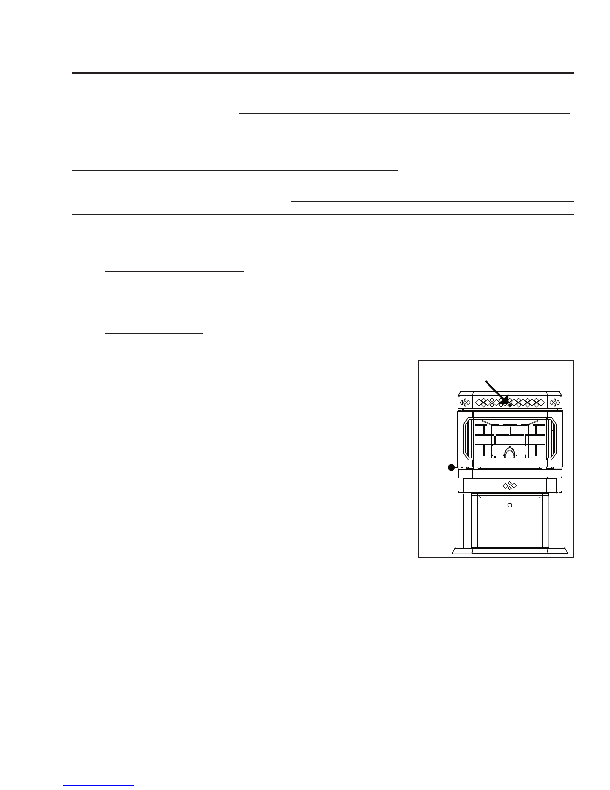
HEAT EXCHANGER TUBES (2-3 days)
The handle for the heat exchanger cleaning rod is pointed out in Figure
9. This handle is to be pulled back and forth a few times (ONLY WHEN
THE UNIT IS COLD) in order to clean away any fly ash that may have
collected on the heat exchanger tubes. As different types of pellets
produce different amounts of ash, cleaning of the tubes should be done
on a regular basis to enable the unit to run efficiently.
.
FRESH AIR INTAKE (season)
Inspect periodically to be sure that it is not clogged with any foreign
materials.
EXHAUST PASSAGES (season)
For bi-weekly clean out, ash may be removed from behind the steel
plates by rotating the circular covers located behind the right and left side panels. Loosen the screw on
the disks and open, this will allow vacuuming behind the firebox liner’s plates.
Removal of the firebox backing for bi-annual cleaning:
• Remove the top baffle.
• Lubricate and then remove the seven (7) screws that hold the brick liner in place. Tilt the top of the
brick panel towards the firebox opening and remove from the firebox
• Remove the top rod by first removing the screw that holds it in place, then slide the rod sideways
• Pull the side panels into the center of the firebox, then out
• Pull the center panel out.
• Clean and vacuum all passages thoroughly.
Figure 9: VF100 Heat exchanger
rod.
11

Routine Cleaning and Maintenance
Installation of firebox backing:
• Install the side panels in place. Insert center panel, hold the panels in place
• Install the top rod by sliding it into one side panel then across into the other panel. Screw rod in
place.
• Re-install steel brick liner and screw in place.
• Replace top baffle
EXHAUST VENT (season)
The products of combustion will contain small particles of flyash. The flyash will collect in the exhaust
venting system and restrict the flow of the flue gases. Incomplete combustion, such as occurs during
startup, shutdown, or incorrect operation of the room heater will lead to some soot formation which
will collect in the exhaust venting system. The exhaust venting system should be inspected at least
once every year or after two tons of pellets to determine if cleaning is necessary. We recommend
contacting your dealer for professional cleaning. To remove dust from the vent pipe, tap lightly on the
pipe to dislodge any loose ash. Open the bottom of the “T” to dump the ash, then vacuum as much of
the ash out of the vent pipe as possible.
BLOWER MECHANISMS (season)
Unplug the stove then open the right/left side panels to access the two blowers. Vacuum all dust from
motors. Only the convection blower motor (on the right side of the stove) will require lubrication. The
convection motor has two lubrication holes on it. Use two drops of SAE 20 light oil to lubricate every six
months. Excess oil may damage the motor. The exhaust blower’s motor has sealed bearings, DO NOT
lubricate this motor.
DOOR GLASS (It is recommended that your dealer replace the glass if broken.)
The door glass is made of 5 mm thick, high temperature PYROCERAMIC. To replace the glass, unscrew
and remove the four glass retainers. Remove the glass and any broken pieces. High temperature
fiberglass tape should be used around the glass. Replace the glass, center the glass assembly in the
frame, then screw the glass retainers back to the frame. The use of substitute materials is prohibited use
only part EF-062.
POST SEASON CLEAN-UP
Once you are finished using the pellet appliance for the season, unplug the stove for added electrical
protection. It is very important that the stove be cleaned and serviced as stated above.
CLEANING PLATED SURFACES
Please clean all fingerprints off of all gold parts, with denatured alcohol on a soft cloth, before firing the
unit each time. Fingerprints, etc. can become permanently etched into the gold if not removed before
operating the pellet heater.
BRICK PANEL
The paint on the steel brick panel may peel. This is due to extreme conditions applied to the paint and is
in no way covered by warranty.
12
 Loading...