

Vistadoor M-E VDV-610 COMPACT, M-E VDV-620 COMPACT, M-E VDV-600, M-E VDV Series, M-E VDV 620 Operating Instructions Manual
...
VDV-610
COMPACT
VDV-620
BETRIEBSANLEITUNG
OPERATING INSTRUCTIONS
MODE D’EMPLOI
GEBRUIKSAANWIJZING
COMPACT
VDV-600 | DEUTSCH
Abb. 1
DIAGRAM 1
ILLUSTRATION 1
AFBEELDING 1
1
3
4
6
22
5
Abb. 2
DIAGRAM 2
ILLUSTRATION 2
AFBEELDING 2
8
9
Abb. 3
DIAGRAM 3
ILLUSTRATION 3
AFBEELDING 3
7
13
1212
140 - 160cm
11
10
2
DEUTSCH | VDV600
EINLEITUNG
Vielen Dank für den Kauf des VISTADOOR Video-Türsprech-Systems.
Sie haben eine hochwertige Anlage mit Edelstahl-Abdeckung gekauft.
Die Edelstahl-Abdeckungen werden aufwändig per Hand gefertigt
und besitzen dadurch individuelle Merkmale, die als ein Zeichen von
Qualität anzusehen sind.
Pflegehinweis Edelstahl
Bitte säubern Sie Edelstahl-Oberflächen nie mit handelsüblichen
Reinigungsmitteln, da diese zu scharf sind. Bitte nur mit Edelstahlreinigungs- bzw. Pflegespray säubern. Sollten Sie dieses nicht zur Hand
haben, bitte nur klares Wasser verwenden.
Gebürstete Oberflächen sollten immer in Strichrichtung gesäubert
werden, nie kreisförmige Bewegungen durchführen. Dadurch werden
Kratzer vermieden.
Wird dieser Pflegetipp nicht beachtet, kann es zu Verfärbungen bzw. im
schlimmsten Fall zu Rostschäden kommen.
Die Montage sollte von einem Fachmann
ausgeführt werden.
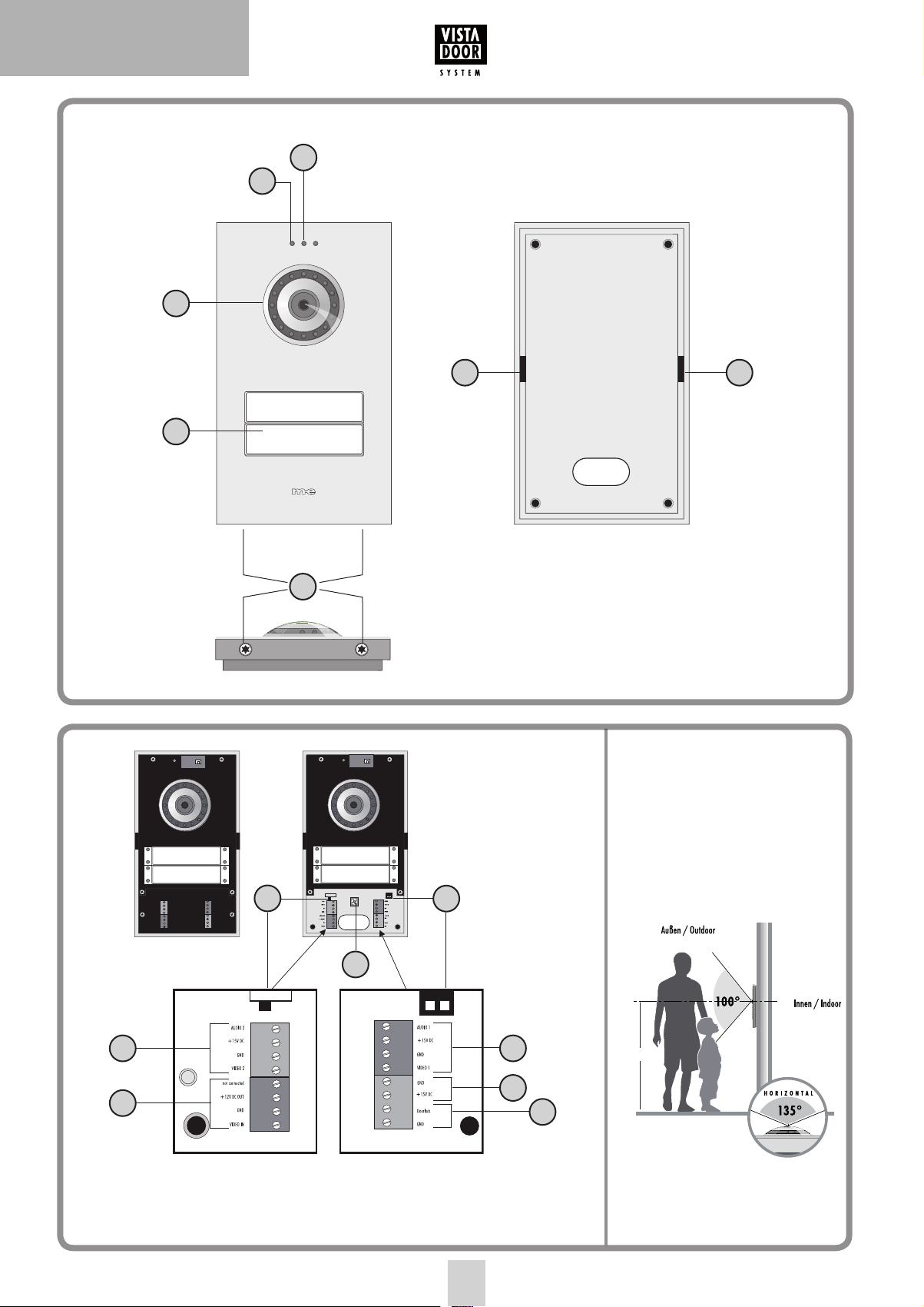
Legende
1. Kamera
2. Lautsprecheröffnungen
3. Klingeltaster
4. Mikrofon
5. Gehäuseschrauben
6. Helligkeitssensor
7. Lautstärke-Potentiometer
8. Dip-Schalter für Öffnungszeit des Türöffners
9. Dip-Schalter für ID-Code
10. Anschlussterminal Türöffner
11. Anschlussterminal Spannungsversorgung
12. Anschlussterminal Signalleitung
13. Anschlussterminal externe Kamera
VORBEREITUNG DER INSTALLATION
Hinweis: Sie können beim VISTADOOR-System auch Videomit Audiokomponenten kombinieren.
MONTAGE DER AUßENSTATION
Vorbereitung
Achten Sie beim Abnehmen des Frontcovers darauf, dass die Namensschilder nicht herausfallen, damit sie nicht beschädigt werden.
Die Kamera sollte in einer Höhe von ca. 1,4m-1,6m (Mitte Kamera)
montiert werden (Abb. 3).
1. Drehen Sie die beiden unteren Schrauben (5) mit einem geeigneten Schraubendreher heraus.
2. Fassen Sie das Frontcover unten mit Daumen und Zeigefinger an
und ziehen Sie es leicht nach vorne. Heben Sie es dann leicht nach
oben ab. Achten Sie darauf, dass Sie das Mikrofonkabel nicht abreißen. Das Mikrofonkabel ist durch einen Stecker mit der Elektronik
verbunden und kann einfach durch Herausziehen getrennt werden.
3. Entfernen Sie die Abdeckung der Anschlussklemmen, indem Sie
die beiden Schrauben herausdrehen und dann das Kunststoff-Cover
herausnehmen.
4. Suchen Sie sich eine geeignete Stelle zur Montage der Außeneinheit und verlegen Sie alle benötigten Leitungen bis dorthin
(Abb. 3).
Hinweis: Achten Sie darauf, dass die Wand am Montageort
gerade und eben ist .
5. Bohren Sie anhand der Bohrschablone vier Löcher (Ø 6 mm) in die
Wand. Dazu richten Sie die Bohrschablone mit einer Wasserwaage
gerade an der Stelle der Wand aus, an der die Außeneinheit
montiert werden soll. Fixieren Sie die Bohrschablone mit Klebeband
und bohren Sie anschließend die vier Löcher.
6. Entfernen Sie die Bohrschablone wieder und stecken Sie in jedes
Loch einen der mitgelieferten Dübel.
7. Führen Sie die Leitung durch die dafür vorgesehene Öffnung auf
der Rückseite der Außeneinheit.
8. Verschrauben Sie die Außenstation jetzt mit den 4 Befestigungsschrauben. Achten Sie darauf, dass sich das Gehäuse beim
Verschrauben nicht verzieht.
Folgende Leitungen werden benötigt:
Einfamilienhaus (VDV-610): 4 Leitungen von der Außeneinheit zur
Inneneinheit sowie 2 Leitungen von der Außeneinheit zum Türöffner.
Zweifamilienhaus (VDV-620): Hier werden pro Klingeltaster 4 Leitungen
von der Außeneinheit in jede Wohneinheit benötigt. D.h. Sie benötigen
8 Leitungen von der Außenstation nach innen (jeweils 4 für Familie 1
und Familie 2), sowie 2 Leitungen für den Türöffner.
Pro Wohneinheit können bis zu vier Inneneinheiten parallel angeschlossen werden. Die Verbindung kann entweder von Innenstation
zu Innenstation gelegt werden oder sternförmig von einem zentralen
Punkt (Verteilerkasten) aus.
Die Leitungen sollten so verlegt sein, dass sie jeweils direkt hinter der
entsprechenden Außen-/Inneneinheit aus der Wand geführt werden.
Anpassen des Namensschildes
Das Namensschild besteht aus zwei transparenten Kunststoffteilen,
welche durch 2 kleine Schrauben miteinander verbunden sind.
9. Entfernen Sie beide Schrauben und nehmen Sie das Namensschild
auseinander. Zwischen den beiden Kunststoffteilen liegt die Folie
für die Beschriftung.
10. Beschriften Sie die Folie mit einem wischfesten Filzstift oder
drucken Sie sich ein Namensschild mit den Abmessungen 71 x 15
mm per PC und Drucker aus.
11. Legen Sie das beschriftete Namensschild (Folie) zwischen beide
Kunststoffteile und verschrauben Sie sie wieder miteinander.
12. Die Namensschilder in die Außenstation einlegen und mit einem
Klebestreifen fixieren.
13. Stecken Sie das Mikrofonkabel wieder in die Buchse und setzen Sie
das Frontcover schräg von oben auf die Außenstation. Achten Sie
darauf, das Mikrofonkabel nicht zu quetschen.
3

VDV-600 | DEUTSCH
Die Nasen des hinteren Covers müssen dabei in die Aussparungen
des Frontcovers greifen.
14. Schieben Sie das Frontcover dann vorsichtig über die Außenstation
und drehen Sie die beiden Befestigungsschrauben (5) wieder in
das Gehäuse.
ANSCHLUSS
Klemmen Sie die verlegte Leitung an Audio 1, +15V, GND und Video
1 (Abb. 2) der Außenstation an und verbinden Sie sie mit der/den
Innenstation/en. An den Innenstationen sind diese ebenfalls vorhanden
und müssen nur 1:1 miteinander verbunden werden.
Hinweis zur Zweifamilienhaus-Version: Pro Wohneinheit ist eine 4-polige
Anschlussklemme vorhanden. Die Anschlussklemmen sind nummeriert.
Anschlussklemme 1 ist für den untersten Klingeltaster, Anschlussklemme 2 für den Klingeltaster darüber.
Anschluss eines Türöffners
Der Türöffner wird direkt mit zwei Leitungen mit der Außenstation verbunden (Abb. 2.). Es ist keine zusätzliche Stromversorgung nötig, um
den Türöffner anzusteuern. Der Türöffner muss für 12 Volt Gleichspannung ausgelegt sein und darf nicht mehr als 1A Strom benötigen. Die
beiden Anschlussklemmen sind mit „Doorlock“ und „GND“ beschriftet,
falls der Türöffner korrekt gepolt werden muss. „GND“ ist Minus.
Anschluss Stromversorgung
Die Stromversorgung kann wahlweise an der Innen- oder Außenstation
angeschlossen werden. Hierzu sind separate Schraubklemmen vorhanden (Abb. 2). Es ist auch möglich, die Stromversorgung direkt an die
Signalleitung anzuschließen, z.B. wenn alle Signalleitungen vom
Sicherungskasten aus zu den Außen- und Inneneinheiten gelegt
wurden. Das Netzteil ist dann mit Masse (GND) und +15V zu verbinden.
Mit einem Netzteil können bis zu 8 Einheiten mit Strom versorgt
werden.
Bei mehr als acht Einheiten wird ein zweites Netzteil benötigt, z.B.
wenn 2 Außen- und 7 Innenstationen eingesetzt werden sollen.
Das zweite Netzteil kann einfach parallel zum ersten Netzteil geschaltet
werden.
Das zweite Netzteil sollte direkt mit einer kurzen Leitung an der am
weitesten entfernten Innen oder Außenstation angeschlossen werden,
damit ein eventueller Spannungsabfall an der Verbindungsleitung
kompensiert werden kann.
Anschluss externe Kamera
An der Schraubklemme (Abb. 2) kann eine externe Kamera angeschlossen werden, um z.B. einen durch die Hauptkamera nicht einsehbaren
Bereich zusätzlich überwachen zu können. Es können alle Kameras
angeschlossen werden, die eine Betriebsspannung von 12 Volt DC
benötigen und ein FBAS-Videosignal liefern.
Die Videoleitung wird an die Klemme (VIDEO IN) und die Masseleitung
an die Klemme (GND) angeschlossen, Betriebsspannung für die
Kamera wird von den Klemmen „+12V DC OUT“ (Pluspol) und „GND“
(Minuspol) abgenommen.
Die externe Kamera hat automatisch die ID 4 (siehe Kapitel ID-Code).
Bei aktiver externer Kamera ist keine Tonübertragung möglich. Bei
Verwendung der VDV 500 XCam wird das X-Modul nicht benötigt.
EINSTELLMÖGLICHKEITEN
An der Außenstation stehen Ihnen folgende Möglichkeiten zur Verfügung, die Anlage auf Ihre persönlichen Gegebenheiten einzustellen:
Lautstärke der Außenstation
Mit dem Potentiometer (7) wird die Sprachlautstärke der Außenstation
eingestellt. Für volle Lautstärke drehen Sie das Potentiometer im
Uhrzeigersinn vorsichtig bis zum Anschlag. Durch Drehen gegen den
Uhrzeigersinn wird die Lautstärke verringert.
ID-Code
Werden mehrere Außenstationen parallel geschaltet (z.B. an Toreinfahrt
und Haus), wird über die DIP-Schalter (9) der ID-Code eingestellt.
Dadurch ist es möglich, die einzelnen Außeneinheiten nacheinander
von einer Inneneinheit zu aktivieren, um z.B. den Erfassungsbereich der
entsprechenden Außeneinheit zu überwachen. Umgeschaltet wird an der
Innenstation mit der „Monitor“-Taste.
ID1 = Schalter 1 „on“, Schalter 2 „on“
ID2 = Schalter 1 “off”, Schalter 2 “on”
ID3 = Schalter 1 “off”, Schalter 2 “off”
Öffnungszeit des Türöffners
Mit dem DIP-Schalter (8) wird eingestellt, wie lange der Türöffner
aktiviert werden soll. Die Einstellmöglichkeiten sind entweder 1
Sekunde oder 5 Sekunden. 5 Sekunden ist ab Werk voreingestellt und
funktioniert für die meisten handelsüblichen Türöffner.
Schalter nach Links auf „5S“ entspricht Öffnungszeit 5 Sekunden.
Schalter nach Rechts auf „1S“ entspricht Öffnungszeit 1 Sekunde.
BEDIENUNG
1. Drücken Sie auf die Klingeltaste.
2. An der/den entsprechenden Innenstation/en ertönt der eingestellte Klingelton und der Bildschirm zeigt das Bild der Außenstation.
3. Nehmen Sie das Gespräch an der Inneneinheit durch kurzen Druck
auf die Sprech-Taste (MUND) an.
4. Ist eine Zusatzkamera an der Außenstation angeschlossen, können
Sie durch Drücken auf die Taste „MONITOR“ auf diese umschalten.
Durch weiteres Drücken auf die „Monitor“-Taste schalten Sie wieder
auf die interne Kamera zurück.
5. Ist ein Türöffner angeschlossen, können Sie durch kurzen Druck auf
die Türöffner-Taste (SCHLÜSSEL) den Türöffner aktivieren.
6. Durch kurzes Drücken der Sprech-Taste (MUND) wird die Anlage
wieder in den Standby-Betrieb geschaltet.
TECHNISCHE DATEN
Betriebsspannung: 15 Volt DC
Stromaufnahme: 130 ± 50 mA
Kamera-Öffnungswinkel: 135° horizontal / 100° vertikal
Temperaturbereich: -10 bis + 50°C
Abmessungen: 114 x 195 x 24 mm (B x H x T ohne Linse)
Türöffner-Anschluss: 12 Volt DC / 1A max.
4

DEUTSCH | VDV600
HINWEISE
Hinweise zur CE - Konformität
Unter Einwirkung von starken statischen, elektrischen oder hochfrequenten Feldern (Entladungen, Mobiltelefonen, Funkanlagen, Handys,
Mikrowellen) kann es zu Funktionsbeeinträchtigungen der Geräte (des
Gerätes) kommen.
Reinigung und Pflege
Netzbetriebene Geräte vor dem Reinigen vom Netz trennen (Stecker
ziehen). Die Oberfläche des Gehäuses kann mit einem mit Seifenlauge
angefeuchtetem weichen Tuch gereinigt werden. Verwenden Sie keine
Scheuermittel oder Chemikalien. Staubablagerungen an Lüftungsschlitzen nur mit einem Pinsel lösen und gegebenenfalls mit einem
Staubsauger absaugen. Die Saugdüse nicht direkt an das Gerät halten.
Sicherheitshinweise
Bei Beschädigung von Gehäusen, Steckern, Netzkabel oder Isolationsschäden, Geräte sofort außer Betrieb nehmen und Netzleitungen abziehen. STROMSCHLAG - LEBENSGEFAHR. (Netzstecker aus der
Steckdose ziehen!) Schäden sofort durch Fachmann beheben lassen!
Keine eigenen Reparaturversuche durchführen!
2 JAHRE BESCHRÄNKTE GARANTIE
Es wird für die Dauer von 2 Jahren ab Kaufdatum gewährleistet, dass
dieses Produkt frei von Defekten in den Materialien und in der Ausführung ist. Dies trifft nur zu, wenn das Gerät in üblicher Weise benutzt
wird und regelmäßig instand gehalten wird. Die Verpflichtungen dieser
Garantie werden auf die Reparatur oder den Wiedereinbau irgendeines
Teils des Gerätes begrenzt und gelten nur unter der Bedingung, dass
keine unbefugten Veränderungen oder versuchte Reparaturen vorgenommen wurden. Ihre gesetzlichen Rechte als Kunde werden in keiner
Weise durch diese Garantie beeinträchtigt.
Zerlegen Sie das Produkt nicht! Es besteht die Gefahr eines
lebensgefährlichen elektrischen Schlages!
Lassen Sie das Verpackungsmaterial nicht achtlos liegen, Plastikfolien/tüten, Styroporteile etc. könnten für Kinder zu einem gefährlichen
Spielzeug werden.
Die Inneneinheiten sind nur für trockene Innenräume geeignet (keine
Badezimmer o.ä. Feuchträume). Vermeiden Sie das Feucht- oder
Nasswerden der Geräte. Es besteht die Gefahr eines lebensgefährlichen
elektrischen Schlages!
In gewerblichen Einrichtungen sind die Unfallverhütungsvorschriften
des Verbandes der gewerblichen Berufsgenossenschaften für elektrische
Anlagen und Betriebsmittel zu beachten. Wenden Sie sich an eine
Fachkraft, wenn Sie Zweifel über die Arbeitsweise, die Sicherheit oder
den Anschluss des Geräts haben.
Gehen Sie vorsichtig mit dem Produkt um - durch Stöße, Schläge oder
dem Fall aus bereits geringer Höhe wird es beschädigt.
DE
Diese Bedienungsanleitung ist eine Publikation der
m-e GmbH modern-electronics,
An den Kolonaten 37, 26160 Bad Zwischenahn
Diese Bedienungsanleitung entspricht dem technischen Stand bei
Drucklegung. Änderung in Technik und Ausstattung vorbehalten.
Haftungsbeschränkung:
Der Hersteller ist nicht für den Verlust oder die Beschädigung
irgendwelcher Art einschließlich der beiläufigen oder Folgeschäden
haftbar, die direkt oder indirekt aus der Störung dieses
Produktes resultieren.
SICHERHEITSHINWEISE
Bei Schäden, die durch Nichtbeachten dieser Bedienungsanleitung
verursacht werden, erlischt der Garantieanspruch. Für Folgeschäden
übernehmen wir keine Haftung!
Bei Sach- oder Personenschäden, die durch unsachgemäße Handhabung
oder Nichtbeachten der Sicherheitshinweise verursacht werden,
übernehmen wir keine Haftung. In solchen Fällen erlischt jeder
Garantieanspruch!
Aus Sicherheits- und Zulassungsgründen (CE) ist das eigenmächtige
Umbauen und/oder Verändern des Produkts nicht gestattet.
Der Aufbau des Produkts entspricht der Schutzklasse 1.
Als Spannungsquelle darf nur eine ordnungsgemäße Netzsteckdose
(230V~/50Hz) des öffentlichen Versorgungsnetzes verwendet werden.
Geräte, die an Netzspannung betrieben werden, gehören nicht in
Kinderhände. Lassen Sie deshalb in Anwesenheit von Kindern besondere
Vorsicht walten.
5
VDV-600 | ENGLISH
INTRODUCTION
Thank you for choosing the VISTADOOR video intercom system. You
have purchased a high quality system with a stainless steel cover.
The elaborate stainless steel covers are made by hand and thus have
individual characteristics that should be considered a sign of quality.
Notes on caring for stainless steel
Please never clean the stainless steel surfaces with standard cleaning
materials, as these are too harsh. Please simply clean using spray designed for the cleaning and care of stainless steel. If this is not available
please use only clear water.
Brushed surfaces should always be cleaned with the grain and never in
a circular motion. This will avoid the creation of scratches.
Failure to observe these notes may lead to discolouration or even to
rust damage in extreme cases.
The system should be assembled by a specialist.
Key
1 Camera
2 Loudspeaker perforations
3 Bell button
4 Microphone
5 Casing screws
6 Lightness sensor
7 Volume potentiometer
8 Dip switch for the opening time of the door opener
9 Dip switch for the ID code
10 Connection terminal door opener
11 Connection terminal power supply
12 Connection terminal signal line
13 Connection terminal external camera
INSTALLATION OF THE OUTDOOR STATION
Preparation
When removing the front cover please ensure that the nameplates do
not fall out as this could damage them.
The camera should be installed at a height of approx. 1.4m-1.6m
(camera centre) (figure 3).
1. Remove the two bottom screws (5) using a suitable screwdriver.
2. Using the thumb and index finger, hold the front cover and pull it
forward slightly. Then gently lift and remove it. Take care not to
tear off the microphone cable. A plug connects microphone cable
and electronics – remove by simply unplugging.
3. Remove the terminal cover by unscrewing the two screws and then
removing the plastic cover.
4. Look for a suitable place to install the outdoor unit and lay the
necessary lines to this point (figure 3).
Note: Ensure that the wall at the installation location is
straight and level.
5. Drill four holes into the wall using the drilling template (Ø 6 mm).
Place the drill template at the outdoor unit installation position
on the wall and use a water level to ensure it is straight. Stick the
drilling template on with sticky tape and then drill the four holes.
6. Remove the drill template and place one of the included dowels in
each drill hole.
7. Feed the line through the designated opening on the reverse of
the outdoor unit.
8. Now screw the outdoor station closed with the 4 fixing screws.
Make sure that the housing does not become distorted when
tightening.
PREPARATION FOR INSTALLATION
The following lines are required:
Single-family house (VDV-610): 4 lines from the outdoor unit to the
indoor unit and 2 lines from the outdoor unit to the door opener.
Duplex house (VDV-620): 4 lines per bell push-button from the outside
unit to each apartment are required here, i.e. you need 8 lines from the
outside station to the inside (4 each per family 1 and 2) and 2 lines for
the door opener.
Up to four indoor units can be connected in parallel per residential unit.
The connection can either be laid from the indoor station or in a star
formation from a central point (distribution box).
The lines should be laid in such a way that they are fed out of the wall
directly behind the relevant outdoor/indoor unit.
Note: It is also possible to combine video and audio components with the VISTADOOR system.
Adjusting the nameplate
The nameplate comprises two transparent plastic parts that are
connected with 2 small screws.
9. Remove both screws and take the nameplate apart. The foil for
inscription is between the two plastic parts.
10. Write on the foil with a smear-resistant felt pen or print a nameplate with the dimensions 71 x 15 mm using a PC and printer.
11. Place the inscribed nameplate (foil) between the two plastic parts
and screw them back together.
12. Lay the nameplates into the outdoor station and fix them with a
strip of adhesive tape.
13. Plug the microphone cable into the socket again and fit the front
cover onto the outside station - from the top and at an angle. Take
care not to pinch the microphone cable. The back cover catches
must hook into the front cover recesses.
14. Thereafter, carefully slide the front cover over the outside station
and screw the two fastening screws (5) back into the enclosure.
CONNECTION
Connect the laid line to Audio 1, +15V, GND and Video 1 (figure 2) on
the outdoor station and connect it with the indoor station/s. These are
also present on the indoor station and need only be connected with one
another 1:1.
6

Note on the duplex house version: one 4-pole connection
terminal is provided per residential unit; the connector terminals are
numbered. Terminal 1 is for the lowest bell button, terminal 2 for the
bell button above it.
ENGLISH | VDV600
ID1 = Switch 1 ‘on’ Switch 2 ‘on’
ID2 = Switch 1 ‘off’ Switch 2 ‘on’
ID3 = Switch 1 ‘off’ Switch 2 ‘off’
Connecting a door opener
The door opener is connected directly to the outdoor station by two
lines (figure 2.2, no. 12). No additional power supply is necessary
to control the door opener. The door opener must be designed for 12
V direct current and may not require more than 1 A current. The two
connector terminals are marked ‘Doorlock’ and ‘GND’ if the door opener
needs to be poled. ‘GND’ is negative.
Connecting the power supply
The power supply can either be connected to the indoor or to the outdoor station. Separate screw terminals exist for this purpose (figure 2).
It is also possible to connect the power supply directly to the signal line,
e.g. if all signal lines have been laid from the fuse box to the outdoor
and indoor units. The power supply unit then needs to be connected
with earth (GND) and +15V.
Up to 8 units can be supplied with power from one power supply unit. A
second power supply unit is required if there are more than eight units,
e.g. if 2 outdoor and 7 indoor stations need to be used.
The second power supply unit can simply be switched parallel to the
first power supply unit.
The second power supply unit should be connected with a short line to
the indoor or outdoor station that is farthest away so that any drop in
current in the connection line can be compensated.
Connecting an external camera
An external camera can be connected to this screw terminal (figure 2)
in order, for example, to provide additional monitoring of areas that
cannot be seen by the main camera. All cameras can be connected that
require operating voltage of 12 V DC and supply an FBAS video signal.
The video line is connected to the terminal (VIDEO IN) and the earth
line to the terminal (GND), operating voltage for the camera is taken
from the terminals ‘+12V DC OUT’ (positive pole) and ‘GND’ (negative
pole).
The external camera automatically has the ID 4 (see chapter on ID
code).
No sound transmission is possible when the external camera is active.
When using the VDV 500 XCam, the X-module is not needed.
Opening time of the door opener
The DIP switch (8) is used to set the time the door opener remains
activated. The options are either 1 second or 5. The factory setting is 5
seconds, which works for most conventional door openers.
Switch to the left to “5S” for 5 seconds open time.
Switch to the right to “1S” for 1 second open time.
OPERATION
1. Press the bell push-button.
2. The preset ring tone sounds on its inside station/s and the screen
displays the outside station view.
3. Accept the dialogue on the inside unit by briefly pressing the pressto-talk button (MOUTH).
4. If an additional camera is present at the outside station, you may
switch over to this camera by pressing the “MONITOR” button.
Pressing the „Monitor“ button again switches you back to the
internal camera.
5. If a door opener is connected then you can activate the door
opener by pressing briefly on the door opener button (KEY).
6. Switch the system back to standby operation by briefly pressing the
speak button (MOUTH).
TECHNICAL DATA
Operating voltage: 15 V DC
Current consumption: 130 ± 50 mA
Camera detection angle: 135° horizontal / 100° vertical
Temperature range: -10°C to +50°C
Dimensions (w x h x d): 114 x 195 x 24 mm (without lens)
Door opener connection: DC 12V, max. 1A
POSSIBLE SETTINGS
The outdoor station offers the following possibilities to set the system
to your personal circumstances:
Volume of the outdoor station
The potentiometer (7) is used to set the volume on the outdoor station.
To set the highest volume, turn the potentiometer carefully clockwise
as far as possible. Reduce the volume by turning in an anti-clockwise
direction.
ID code
If several outdoor stations are switched in parallel (e.g. at the gate entrance and the house) then the ID code is set via the dip switch (9). This
makes it possible to activate the individual outdoor units in sequence,
e.g. in order to monitor the coverage of the relevant outdoor unit. The
switch is carried out on the indoor station with the ‘monitor’ switch.
INFORMATION
Information regarding CE - Conformity
The functionality of the unit can be affected by the influence of strong
static, electrical or high frequency fields (discharging, mobile phones,
radios, microwaves).
Cleaning and maintenance
Always disconnect mains powered units from the mains supply before
cleaning (disconnect the plug). The unit housing can be cleaned using
a soapy soft cloth. Do not use any abrasive materials or chemicals.
Remove dust build-up from ventilation slits using a brush and clean up
using a vacuum cleaner. Do not hold the vacuum cleaner nozzle directly
against the unit.
Safety instruction
In the event of damage to the housing, connectors, power cables or
isolation shielding, switch off the device immediately and disconnect
from the mains power. ELECTRIC SHOCK – DANGER OF
LOSS OF LIFE. (Unplug the mains connector from the socket!).
7

VDV-600 | ENGLISH
Damage should be repaired immediately by a specialist!
Never carry out repairs yourself!
Warranty
2 years warranty from date of purchasing, on base of correct using.
The producer is not responsible for consequential damages which are
effected directly or indirectly from this item.
SAFETY NOTES
The warranty will be null and void in case of damages arising from
violations of these operating instructions. We are not liable for
consequential damages!
We accept no liability for material damages or injuries arising from
inappropriate use or violation of the safety instructions. In such cases
all warranty claims are null and void!
For reasons of safety and licensing (CE), unauthorised conversion and /
or modification of the product is prohibited.
The design of the product complies with protection class 1. Only a
standard mains socket (230V~/50Hz) of the public mains supply may
be used to power the device. Devices powered by mains voltage must
be kept away from children. Please therefore be particularly careful in
the presence of children.
Do not take the product apart! There is a danger of lethal
electric shock!
Do not leave packaging material lying about since plastic foils and
pockets and polystyrene parts etc. could be lethal toys for children.
The interior units are suitable only for dry interior rooms (not bathrooms and other moist places). Do not allow the devices to get moist
or wet. There is a danger of lethal electric shock!
In industrial institutions, the accident prevention regulations of the
Association of Commercial Professional Associations for electrical installations and equipment must be observed. Please consult a specialist
should you have doubts regarding the method of operation, the safety,
or the connections of the device.
Handle the product with care – it is sensitive to bumps, knocks or falls
even from low heights.
GB
These operating instruction are published by
m-e GmbH modern-electronics,
An den Kolonaten 37, 26160 Bad Zwischenahn/Germany
The operating instructions reflect the current technical specifications at
time of print. We reserve the right to change the technical or physical
specifications.
8

FRANÇAIS | VDV600
INTRODUCTION
Nous vous remercions pour l’achat du système d’interphone vidéo de
VISTADOOR. Vous venez d’acquérir une installation haut de gamme
avec un couvercle en acier inoxydable. Les couvercles en acier inoxydable sont fabriqués à la main et possèdent ainsi une touche individuelle
à considérer comme un signe de qualité.
Consignes d’entretien de l’acier inoxydable
Ne nettoyez jamais les surfaces en acier inoxydable avec des détergents
classiques qui sont trop abrasifs. Utilisez uniquement un détergent ou
un spray spécial pour l’acier inoxydable. Si vous n’en avez pas, utilisez
uniquement de l’eau claire.
Les surfaces brossées doivent toujours être nettoyées dans le sens des
rainures, n’effectuez jamais de cercles en nettoyant. Vous éviterez ainsi
de rayer la surface.
Si vous ne respectez pas cette consigne, vous pouvez provoquer des
décolorations ou même l’apparition de rouille.
Le montage doit être effectué par un spécialiste.
Légende
1. Caméra
2. Enceinte du haut-parleur
3. Sonnette
4. Microphone
5. Vis du boîtier
6. Capteur de luminosité
7. Potentiomètre de volume
8. Commutateur DIP pour le temps d’ouverture de la gâche électrique
9. Commutateur DIP pour le code ID
10. Terminal de connexion gâche
11. Terminal de connexion alimentation électrique
12. Terminal de connexion circuit de signalisation
13. Terminal de connexion caméra externe
Remarque : vous pouvez également combiner le système
VISTADOOR avec des composants vidéo et audio.
MONTAGE DE LA STATION EXTÉRIEURE
Préparation
Lorsque vous retirez le couvercle frontal, veillez à ce que les étiquettes
nominative ne tombent pas, pour ne pas les endommager.
La caméra doit être montée à une hauteur de 1,4 - 1,6 m (caméra au
centre) (fig. 3).
1. Retirez les deux vis du bas (5) avec un tournevis adapté.
2. Tenez la couverture frontale en bas avec le pouce et l‘index puis
tirez-le doucement vers l‘avant. Soulevez-le ensuite légèrement
vers le haut. Veillez à ne pas déchirer le câble du microphone.
Le câble frontal est relié avec le système électronique par un
connecteur et se retire facilement en tirant.
3. Retirez le couvercle de la borne de raccordement en desserrant les
deux vis puis en retirant le couvercle en plastique.
4. Recherchez un endroit adapté pour le montage de l’unité extérieure
et installez tous les câbles nécessaires (fig. 3).
Remarque : veillez à ce que le mur soit droit et lisse sur le
lieu de montage.
5. Percez 4 trous (Ø 6 mm) dans le mur avec le gabarit de perçage.
Ajustez ensuite le gabarit de perçage avec un niveau à bulle sur le
mur sur lequel l’unité extérieure doit être montée. Fixez le gabarit
de perçage avec de la bande adhésive et percez ensuite les 4 trous.
6. Retirez le gabarit et insérez les chevilles fournies dans chaque trou.
7. Insérez le câble dans l’orifice prévu à cet effet au dos de l’unité
extérieure.
8. Vissez maintenant la station extérieure avec les 4 vis de fixation.
Assurez-vous que le boîtier ne se déforme lors du serrage.
PREPARATION POUR L’INSTALLATION
Les câbles suivants sont nécessaires :
Maison particulière (VDV-610) : 4 câbles de l’unité extérieure vers
l’unité intérieure ainsi que 2 câbles de l’unité extérieure vers la gâche.
Maison de deux appartements (VDV-620) : chaque sonnette nécessite
4 câbles partant de l‘unité extérieure vers chaque unité d‘habitation.
C‘est-à-dire qu‘il vous faut 8 câbles partant de la station extérieure vers
l‘intérieur (4 pour la famille 1 et autant pour la seconde) ainsi que 2
câbles pour la gâche électrique.
Il est possible de connecter en parallèle jusqu’à 4 unités intérieures
par unité d’habitation. La connexion peut être installée soit depuis la
station intérieure ou en forme d’étoile depuis un point central (boîte
de répartition).
Les câbles doivent être installés de telle sorte à être guidés directement
derrière l’unité extérieure/intérieure correspondant.
Ajuster l’étiquette avec le nom
L’étiquette avec le nom se compose de deux pièces en plastique
transparent que vous pouvez relier avec 2 petites vis.
9. Retirez les deux vis et séparez l’étiquette. L’étiquette nominative se
situe entre les deux pièces en plastique.
10. Inscrivez le nom sur le papier avec un feutre indélébile ou imprimez
une étiquette avec les dimensions 71 x 15 mm avec l’ordinateur et
l’imprimante.
11. Insérez l’étiquette (feuille) entre les deux pièces en plastique et
vissez-les de nouveau ensemble.
12. Posez les étiquettes dans la station extérieure et fixez-les avec de la
bande adhésive.
13. Insérez de nouveau le câble du microphone dans la douille puis
reposez le couvercle frontal obliquement depuis le haut sur la
station extérieure. Veillez à ne pas écraser le câble du microphone.
Ce faisant, les embouts du couvercle arrière doivent s‘emboîter
dans les ouvertures du couvercle frontal.
14. Poussez alors prudemment le couvercle frontal sur la station
extérieure et revissez les deux vis de fixation (5) dans le boîtier.
9
VDV-600 | FRANÇAIS
BRANCHEMENT
Branchez le câble posé au Audio 1, +15V, GND et Video 1 (fig. 2) de
la station extérieure et connectez-le à la (les) station(s) intérieure(s).
Ces systèmes sont également disponibles sur les stations intérieures et
doivent uniquement être branchés 1 :1.
Remarque sur la version pour maison de deux appartements : Il y a une
borne de raccordement à 4 pôles par unité d’habitation. Les bornes de
raccordement sont numérotées. La borne de raccordement 1 est prévue
pour la sonnette du bas, la borne 2 pour la sonnette suivante.
Raccordement d’une gâche
La gâche est branchée directement par deux câbles sur la station
extérieure (fig. 2). Aucun système d’alimentation supplémentaire n’est
nécessaire pour commander la gâche. La gâche doit être équipée pour
une tension continue de 12 Volt et ne doit pas consommer plus d’1 A
de courant. Les deux bornes de raccordement comprennent l’inscription
« Doorlock » et « GND » pour le cas où la gâche doit être polarisée
correctement. GND est négatif.
Raccordement à l’alimentation électrique
L’alimentation électrique peut être branchée au choix sur la station
intérieure ou la station extérieure. Une borne à vis séparée est prévue à
cet effet (fig. 2). Il est également possible de connecter l’alimentation
directement au circuit de signalisation, par ex. lorsque tous les circuits
de signalisation de la boîte à fusibles des unités extérieure et intérieure
sont occupés. Le bloc d’alimentation doit être branché avec la masse
(GND) et + 15 V.
Un bloc d’alimentation permet d’approvisionner jusqu’à 8 unités.
Utilisez un second bloc d’alimentation pour plus de huit unités, par
ex. lorsque 2 stations extérieures et 2 stations intérieures doivent être
installées.
Le second bloc d’alimentation peut être simplement installé en
parallèle par rapport au premier.
Le second bloc d’alimentation doit être branché directement avec un
câble court sur la station intérieure ou extérieure la plus proche afin de
pouvoir compenser une éventuelle baisse de tension au niveau du câble
de connexion.
Raccordement de la caméra extérieure
Une caméra externe peut être branchée sur cette borne à vis (fig. 2)
afin de, par exemple, pouvoir surveiller une zone hors de portée de la
caméra principale. Toutes les caméras avec une tension d’exploitation
de 12 V DC et qui fournissent un signal vidéo FBAS peuvent être
branchées.
Le câble vidéo se connecte à la borne (VIDEO IN) et le câble de masse
à la borne (GND). La tension d’exploitation pour la caméra provient des
bornes « +12V DC OUT » (pôle positif) et « GND » (pôle négatif).
La caméra externe a automatiquement l’ID 4 (cf. chapitre code-ID).
Aucun transfert de son n’est possible lorsque la caméra extérieure est
active. Le module X n‘est pas requis lors de l‘utilisation de la VDV 500
XCam.
Volume de la station extérieure
Le potentiomètre (7) vous permet de régler le son de la station extérieure. Pour un volume maximal, tournez délicatement le potentiomètre
dans le sens des aiguilles d’une montre jusqu’à la butée. Vous pouvez
réduire le volume en tournant le potentiomètre dans le sens inverse.
Code ID
Si vous branchez plusieurs stations extérieures en parallèle (par ex.
entrée du portail et maison), réglez le code-ID avec le commutateur DIP
(9). Vous aurez ainsi la possibilité d’activer chacune des unités extérieure séparément de l’unité intérieure afin de, par exemple, surveiller la
zone correspondant à l’unité extérieure. La touche « écran » permet de
commuter sur la station intérieure.
ID1 = commutateur 1 « on », commutateur 2 « on »
ID2 = commutateur 1 « off », commutateur 2 « on »
ID3 = commutateur 1 « off », commutateur 2 « off »
Durée d’ouverture de la gâche
La durée d‘activation du système d‘ouverture de porte se règle via le
commutateur DIP (8). Les possibilités de réglage sont 1 ou 5 secondes.
La durée de 5 secondes est réglée à l‘usine et fonctionne pour la
plupart des systèmes d‘ouverture de porte commercialisés.
Le commutateur à gauche sur « 5S » correspond à une durée
d‘ouverture de 5 secondes.
Le commutateur à droite sur « 1S » correspond à une durée d‘ouverture
de 1 seconde.
MODE D‘EMPLOI
1. Appuyez sur la sonnette.
2. La / les station(s) intérieure(s) émettent la sonnerie réglée et
l‘écran affiche l‘image de la station extérieure.
3. Appuyez brièvement sur la touche de conversation (BOUCHE) pour
entamer une conversation.
4. Si une caméra supplémentaire est raccordée à la station extérieure,
appuyez brièvement sur la touche « ECRAN » pour l‘activer. En
appuyant une seconde fois sur « ECRAN », vous revenez à la
caméra interne.
5. Si une gâche est branchée, vous pouvez l’activer en appuyant
brièvement sur la touche d’ouverture (CLE).
6. Vous pouvez remettre l’installation en mode Standby en appuyant
encore une fois sur la touche de discussion (BOUCHE).
CARACTÉRISTIQUES TECHNIQUES
Tension de service : 15 Volt DC
Courant absorbé : 130 ± 50 mA
Angle de détection: 135° horizontal / 100° vertical
Plage de température : -10 bis + 50°C
Dimensions (lxhxp): 114 x 195 x 24 mm (sans lentille)
Connexion d‘un syst.
d‘ouverture de porte: DC 12V, max. 1A
REGLAGES POSSIBLES
Vous disposez des possibilités suivantes sur la station extérieure pour
adapter l’installation à vos besoins personnels :
CONSIGNES
Consignes concernant la conformité CEE
L‘influence de forts chants statiques, électriques ou haute fréquence
10
 Loading...