

Vista Acoustics C61 Product Information And Installation Manual
Product Overview
The C61 is a connecting block device for connecting IR receivers, IR emitters and a power supply. This central control unit features an amplifier circuit for driving up to 4 IR emitters and/or
up to 2 high output IR blasters (any combination of 4 total). A 4/P connector and a 3.5mm
Quad mini-jack make for easy connection of IR receivers.
Product Features
1. The C61 has built-in amplifier circuit for driving up to 4 IR emitters and /or up to 2 high output IR blasters (any combination of 4 total).
2. Two separate connections are available for IR Receivers: Input 1: Uses a 3.5mm Quad minijack; Input 2: Uses a 4/position connector: “V+ (12VDC), G (Ground), ST (Status) and IR
(Signal)” Refer to the diagram below for connection. Some IR receivers do not have ST.
3. The “ST OUT” provides status power from 12V trigger output or wall type power supply plugged into the switched output of an A/V receiver.
4 The C61 cable extension distance can provide up to 300M lengths of wire between IR set
to C61 system. When switching to “NET ON”, the C61 cable extension distance increases
up to 400M lengths from IR set to C61
5. NET Amp circuits provide better performance for high data rate of IR codes.
Product Specifications
IR Receiver Connections: Connect the IR receiver to the 4/position connector marked V+
(12VDC), G (GND), ST (Status) and IR (Signal). Note: Select receivers do not offer ST. A 2nd IR
receiver connection is available via the Jack marked “IR RCVR”. Please refer below for the proper connections.
IR Emitter and/or Blaster Outputs: “See diagram 3”. This central control unit features an
amplifier circuit for driving up to 4 IR emitters and/or up to 2 high output IR blasters (any combination of 4 total). Either Single and/or Dual IR emitters, connect up to 4 emitters to the emitter jacks marked 1-4. Place the emitters on the source equipment, up to 8 sources available.
When connecting the BP10 Blaster only plug them into the jacks appropriately marked and
move the switch to the ON position to activate the Blaster output circuitry.
Net On: The NET ON position should be selected when using longer lengths of cable (over 50
feet shielded in particular) between the IR receiver, Keypad, etc. and the C61. This ensures better performance for the IR signal. If you are using two or more C61’s, be sure ONLY ONE of
C61’s is in the “NET ON” position. “See diagram 2”
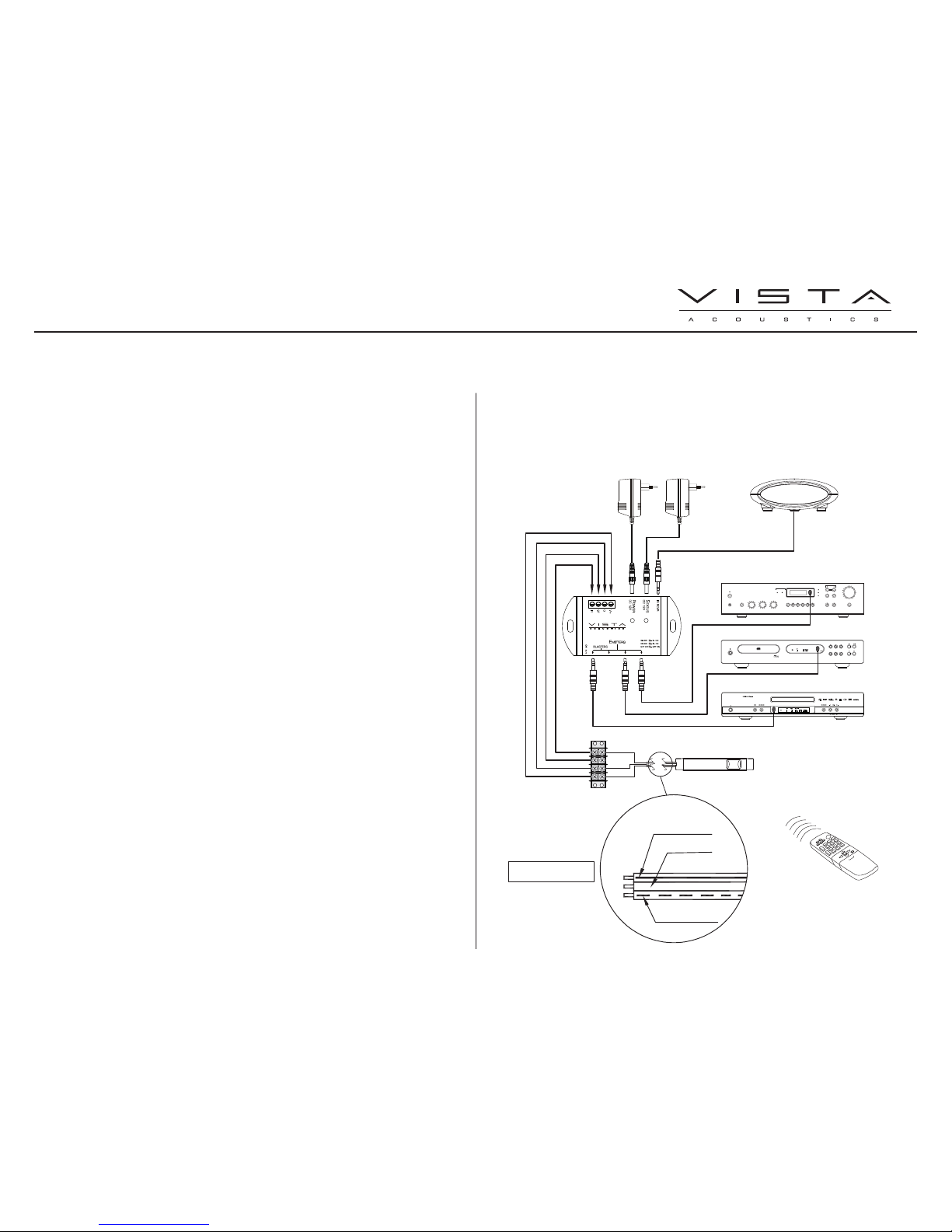
Power: At minimum, connect a Regulated 12VDC/500mA power adaptor for System #1, yet
use a Regulated 12VDC/1.2A power adaptor for System Diagrams #2 and #3.
Status Power: A 12VDC/200mA “2.1mm + tip –sleeve”. Connecting a power supply to this
connection will power the status connection. The green LED will illuminate when powered. This
can be from a 12V trigger output or from a wall type power supply plugged into a switched
outlet of a stereo receiver. Note: Not all IR Receivers feature ST (Status) capability.
Mounting: Install the C61 near the source equipment that the emitters are attached to. The
C61 can be mounted with double stick tape, cable ties, etc.
System Diagram 1:
C61 4 IR Emitter or Selectable Blaster Outputs; Amplified Infrared
Connecting Block With IR Receiver Connection
PRODUCT INFORMATION AND INSTALLATION GUIDE
+12V
GND
ST OUT
IR IN
DC12V
DC12V 200mA
A/V RECEIVER
CD PLAYER
DVD PLAYER
CompactDiscPlayer
OPEN
PLAYPAUSE
STOP
TIME
RANDOM
SCAN
SKIP
REPEAT
SEC
678
9
10
MIN
BASS
TREBLE
BALANCE
VOLUME
TAPE 1
MONITOR
TAPE 2
VCR
LD
AUX
CD
PHONES
EXTRA
SPEAKERS
AM
FM
MONO
SEARCH
TUNE
PRESET
FM
STEREO
CENTER
TUNE
MODE STORE
TUNE
VIDEO
RS31.1
V+: BLACK WITH
GREY SOLID STRIPE
G: BLACK
BACK VIEW FOR
CODING & DEFINITION
REMOTE CONTROL
IR: BLACK WITH GREY
DASHED STRIPE
RT34.1
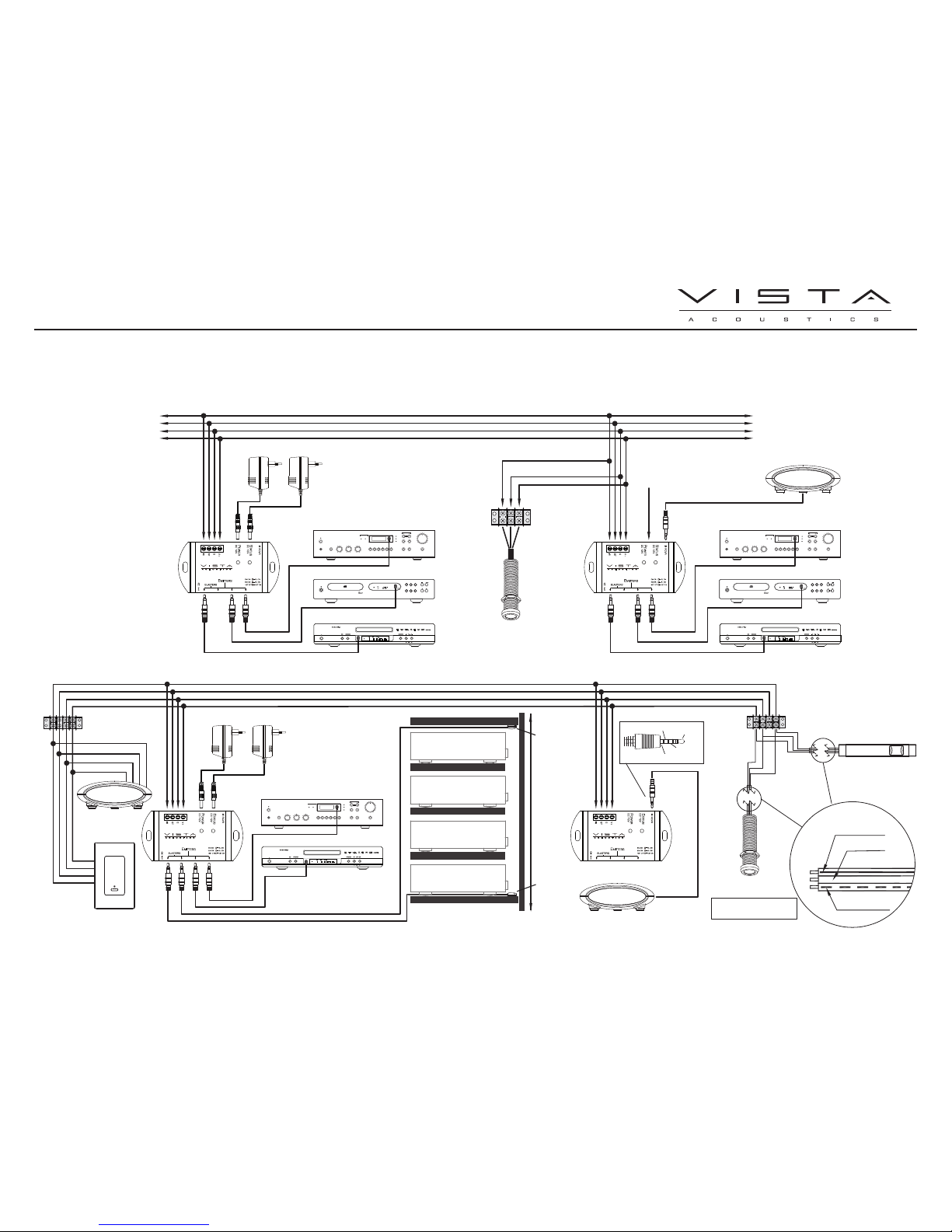
System Diagram 2:
System Diagram 3:
C61 4 IR Emitter or Selectable Blaster Outputs; Amplified Infrared
Connecting Block With IR Receiver Connection
PRODUCT INFORMATION AND INSTALLATION GUIDE
In North America contact: Trends Electronics International Inc. - 100 – 980 West 1st Street. North Vancouver, B.C. V7P 3N4 Phone: 1 (877) 946-9255 Fax: 1 (800) 618-7363 Email: orders@trendsinc.com
+12V
GND
STATUS
IR
DC12V 1,2A
DC12V 200mA
A/V RECEIVER
CD PLAYER
DVD PLAYER
CompactDiscPlayer
OPEN
PLAYPAUSE
STOP
TIME
RANDOM
SCAN
SKIP
REPEAT
SEC
678
9
10
MIN
BASS
TREBLE
BALANCE
VOLUME
TAPE 1
MONITOR
TAPE 2
VCR
LD
AUX
CD
PHONES
EXTRA
SPEAKERS
AM
FM
MONO
SEARCH
TUNE
PRESET
FM
STEREO
CENTER
TUNE
MODE STORE
TUNE
VIDEO
A/V RECEIVER
CD PLAYER
DVD PLAYER
CompactDiscPlayer
OPEN
PLAYPAUSE
STOP
TIME
RANDOM
SCAN
SKIP
REPEAT
SEC
678
9
10
MIN
BASS
TREBLE
BALANCE
VOLUME
TAPE 1
MONITOR
TAPE 2
VCR
LD
AUX
CD
PHONES
EXTRA
SPEAKERS
AM
FM
MONO
SEARCH
TUNE
PRESET
FM
STEREO
CENTER
TUNE
MODE STORE
TUNE
VIDEO
RW32.1
RT34.1
NOTE: DO NOT CONNECT A POWER
SUPPLY TO THIS OR OTHER
SUBSEQUENT C61 ON THE NETWORK.
TO ADDITIONAL C61 OR
OTHER ROOMS IF NEEDED
TO ADDITIONAL C61 OR
OTHER ROOMS IF NEEDED
RECEIVER SIDE VIEW
SHELF
SHELF
SHELF
DVD PLAYER SIDE VIEW
SHELF
VCR SIDE VIEW
SHELF
SAT DECODER SIDE VIEW
BP10
BP10
2 METERS / 78 INCHES
12 VDC
IR SIGNAL
STATUS
GROUND
RS31.1
BACK VIEW FOR
CODING & DEFINITION
V+: BLACK WITH
GREY SOLID STRIPE
G: BLACK
IR: BLACK WITH GREY
DASHED STRIPE
RW32.1
+12V
GND
STATUS
IR
DC12V 1,2A
DC12V 200mA
A/V RECEIVER
DVD PLAYER
BASS
TREBLE
BALANCE
VOLUME
TAPE 1
MONITOR
TAPE 2
VCR
LD
AUX
CD
PHONES
EXTRA
SPEAKERS
AM
FM
MONO
SEARCH
TUNE
PRESET
FM
STEREO
CENTER
TUNE
MODE STORE
TUNE
VIDEO
RT34.1
RT34.1
RB33.1
+12V: ORANGE
GND: BLUE
STATUS: PURPLE
IR: YELLOW
 Loading...