

Vista VS50 Installation Manual
VS50 Installation Guide V1.0
Installation Guide for
VS50 ANPR Camera

VS50 Installation Guide V1.0
Contents
................................................................................................................. Error! Bookmark not defined.
Installation Guide for VS50 ANPR Camera .............................................................................................. 1
1. Component List ................................................................................................................................... 4
1.1 Standard Components ............................................................................................................ 4
1.2 Optional Components ............................................................................................................. 4
2. Introduction ........................................................................................................................................ 4
3. Connections ........................................................................................................................................ 5
4. Connection to PSU .............................................................................................................................. 6
5. Network Connection ........................................................................................................................... 6
6. Relay Connection ................................................................................................................................ 6
7. Camera Configuration (Software) ....................................................................................................... 7
7.1 First time run and setup wizard .................................................................................................... 7
7.1.1 Setup Wizard – Navigating between the pages ..................................................................... 7
7.1.2 Setup Wizard – System Use ................................................................................................... 8
7.1.3 Setup Wizard – Device Setup ................................................................................................. 9
7.1.4 Setup Wizard – Lane Settings ................................................................................................. 9
7.1.5 Setup Wizard – Regions ....................................................................................................... 10
7.1.6 Setup Wizard – Detection .................................................................................................... 11
7.1.7 Setup Wizard – Stream to JetParking Server ....................................................................... 12
7.1.8 Setup Wizard – TCP/IP XML ................................................................................................. 13
7.1.9 Setup Wizard – Software Trigger ......................................................................................... 15
7.1.10 Setup Wizard – Relay Control ............................................................................................ 16
7.1.11 Setup Wizard – Email ......................................................................................................... 16
7.1.12 Setup Wizard – BOF ........................................................................................................... 17
7.1.13 Setup Wizard – Wiegand .................................................................................................... 18
7.1.14 Setup Wizard – LED Sign .................................................................................................... 19
7.1.15 Setup Wizard – Parking Logic ............................................................................................. 20
7.1.16 Setup Wizard – PlateTech .................................................................................................. 21
7.1.17 Setup Wizard completion................................................................................................... 22
7.2 Camera Viewer and Camera Alignment ...................................................................................... 23
7.3 Database and Alarms Setup ........................................................................................................ 24
7.3.1 Manually adding a database through the webpage ............................................................ 24
7.4 The Event Viewer Page ............................................................................................................... 25
7.5 Maintenance ............................................................................................................................... 26

VS50 Installation Guide V1.0
7.5.1 Upload / Download Manager............................................................................................... 26
7.5.2 Diagnostics ........................................................................................................................... 26
7.5.3 System Restore .................................................................................................................... 27
7.5.4 System Function - Test Outputs and Shutdown .................................................................. 28
7.5.5 Passwords ............................................................................................................................ 28
7.5.6 Date / Time Management .................................................................................................... 29
8. Mounting the Camera ....................................................................................................................... 30
9. Troubleshooting ................................................................................................................................ 30
10. Camera Specification (Subject to change) ...................................................................................... 31

VS50 Installation Guide V1.0
1. Component List
1.1 Standard Components
VS50 ANPR Camera
RJ45 Mating Kit
1.2 Optional Components
PSU 24v Dc ( VS50-PSU )
I/O Relay Cable ( VS50-IO-CBL)
2. Introduction
The ANPR camera comes pre‐aligned and set up for a stated distance. These distances relate to
standard UK number plates for use with ANPR software. The system is designed to provide an image
4m wide at the stated distance.
When not using standard UK plates please allow for difference in font size and adjust distance
accordingly.
For help or assistance with your particular installation please contact our technical support team.
The ANPR camera is a combination of camera(s), lens and cool running Infra‐Red technology – all in a
protected housing, and calibrated for immediate use. The unit is supplied ready to run from a 24V
DC input.
The system is designed so that the camera and infra-red or white light illumination work in
conjunction to provide high quality pictures of the number plate on a 24 hour basis. In overcast days
and in low light – the system will still provide excellent images of the number plate. The LED’s are
pulsed at a very high frequency to achieve maximum performance with minimal power
consumption.
The ANPR camera is designed to work with retro‐reflective number plates found in the UK, the
majority of Europe and most parts of US and Canada. For non-retro-reflective plates, such as found
in the Middle East, the white-light version should be used. If you are unsure about the nature of your
number plates, please do not hesitate to contact us.

VS50 Installation Guide V1.0
Figure 1: Pin assignments 3-pin front-view
Figure 2: Pin assignments 8-pin front-view
3. Connections
There are three connectors on the underside of the VS 50 camera:
1. 24VDC, three pin standard male M12, IP68 rated power connector.
Pin 1 = 24V DC
Pin 3 = 0V DC
Pin 4 = Ground
2. An RJ45, IP67 rated network connector.
A mating kit is provided with the unit and must be used to maintain the IP rating of the
camera. A complete shielded network cable with RJ45 should be fed through the mating
connector, and then the sealing nut tightened to create a secure, weather proof grip onto
the cable.
Please see section 5 below for detailed network configuration.
3. An 8-pin standard female M12, IP68 rated connector
for relays and Wiegand
Pin 1 = Ground
Pin 2 = Card Load (Wiegand)
Pin 3 = Data 1 (Wiegand)
Pin 4 = Data 2 (Wiegand)
Pin 5 = Input -ve
Pin 6 = Input +ve
Pin 7 = Output 2 ‘Lights’
Pin 8 = Output 1 ‘Barrier’
A 5m cable with a pre-fitted M12 cable connector, can be purchased from Norbain (VS50-IOCBL). Alternatively, a standard M12 female connector can be independently purchased. It is
recommended that the IP68 rating should be used to preserve the rating of the unit. For
reference, the manufacturer’s part number for the M12 connector on the housing is 1208PMMS-SF8001.

VS50 Installation Guide V1.0
4. Connection to PSU
The VS50 camera requires 24V DC power. Its power consumption is less than 25W under all
conditions. An appropriate power supply unit can be purchased from Norbain SD (VS50-PSU), please
contact your account manager for more details.
When using the power cable to connect to the PSU, the cable colours are as per below:
Red = 24V DC
Blue = 0V DC
Green = Ground
5. Network Connection
The VS50 camera must be connected to a 10/100/1000 Base-T(X) to allow communication to the
device through a web-browser or a computer running Vista Number plate recognition server
software.
The default IP address of the VS50 camera is:
192.168.127.10
The address of every VS50 camera on a given network must be unique and appropriate for
communication with the ANPR computer.
6. Relay Connection
When using the relay cable supplied by Norbain as an option, one end will be fitted with an M12 8pin male connector which should be securely fitted to the camera housing. The other end will have
8, different-coloured, cables which are assigned as per the table below:
Pin Number
Description
Wire colour
1
Ground
Brown
2
Card Load (Wiegand)
Green
3
Data 1 (Wiegand)
White
4
Data 2 (Wiegand)
Yellow
5
Input -ve
Blue
6
Input +ve
Red 7 Output 2 ‘Lights’
Violet
8
Output 1 ‘Barrier’
Black
VS50 Installation Guide V1.0
7. Camera Configuration (Software)
The VS50 camera runs a webpage to enable easy setup and configuration of the device. All settings
are controlled from here so there is no need to connect through remote desktop or other viewing
software.
7.1 First time run and setup wizard
To connect to the VS50, first ensure that your computer is on the same network range (i.e.
192.168.127.n, where ‘n’ is any number from 1 to 255 except 10).
Once your network settings are configured launch a web browser, such as Internet Explorer 11,
Chrome v51, or Firefox v47, and enter the camera’s IP address http://192.168.127.10
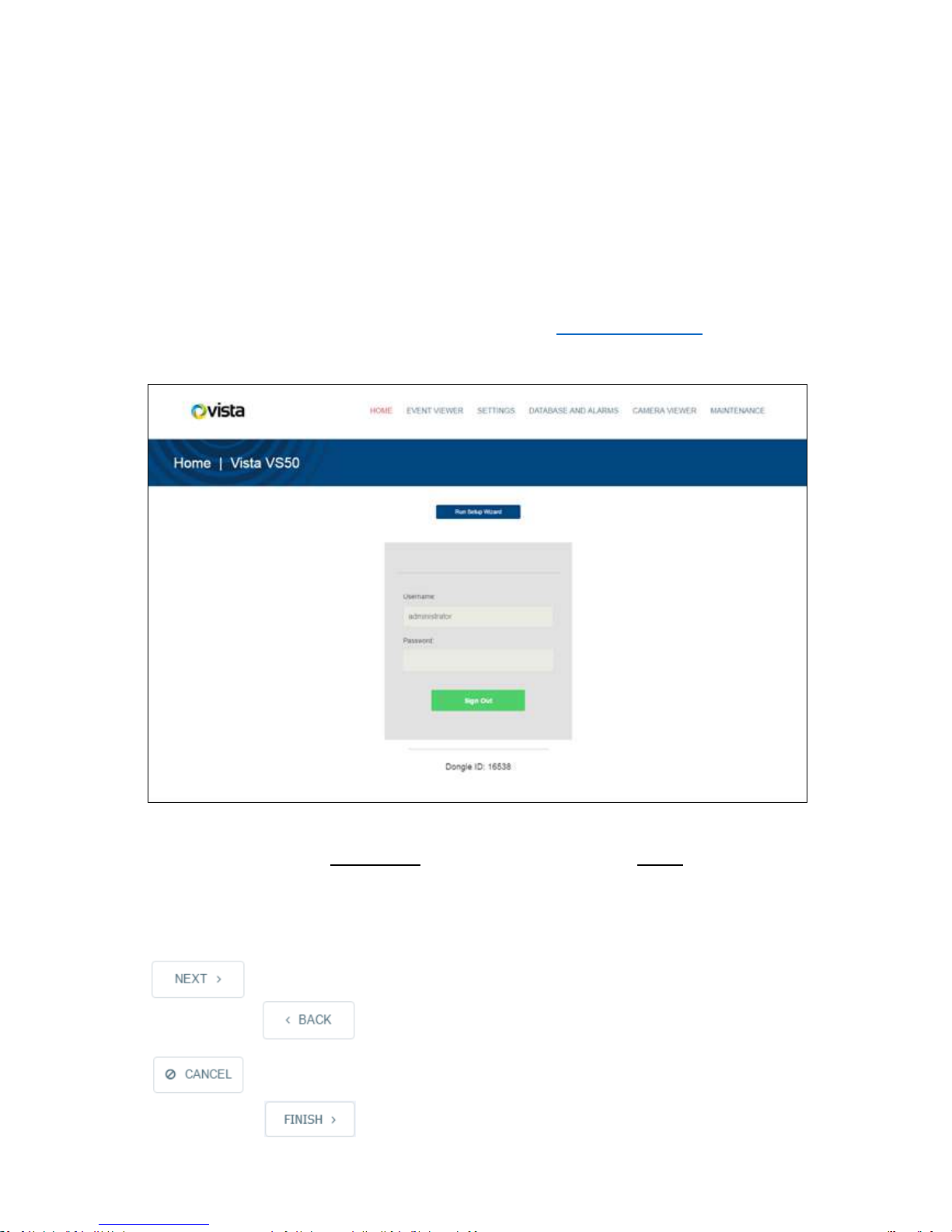
This will bring you to the VS50 homepage (Figure 3 below).
Figure 3: CS-50 Camera Homepage
In the ‘Username’ box, type administrator and in the ‘Password’ box, leave [blank]. To go to the
‘Event Viewer’ page you can click ‘Enter’ however for first run, it is recommended that you click ‘Run
Setup Wizard’.
7.1.1 Setup Wizard – Navigating between the pages
To move to the next menu in the Wizard click on the ‘Next’ button.
To go back to a previous page, click the ‘Previous’ button.
To cancel out of the wizard without making any changes, click the ‘Cancel’ button.
VS50 Installation Guide V1.0
Once you reach the final page for configuration of your system, click the ‘Finish’ button to save and
deploy the settings.
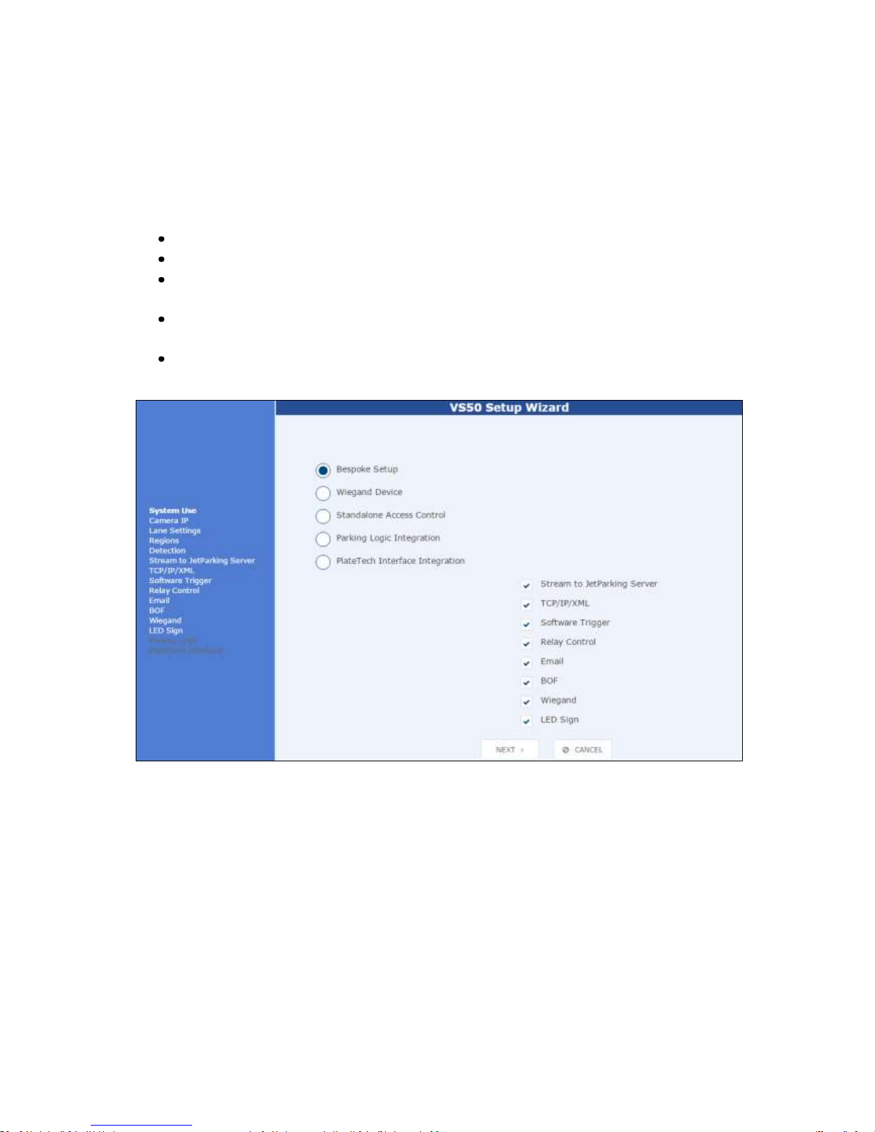
7.1.2 Setup Wizard – System Use
After clicking to run the setup wizard, a new window for the ‘VS50 Configuration Wizard’ will open
showing the ‘System Use’ page (Figure 4 below). On this first page, there are 5 options for the
system use available to you:
Bespoke Setup – All menus can be selected for configuration
Wiegand Device – For when only a Wiegand output is required from the camera
Standalone Access Control – For basic access control features (streaming to JetParking
server; relay control; Email setup; LED sign integration
Parking Logic Integration – For the SkiData UK integration including additional stream relay
and BOF communications
PlateTech Interface Integration – For the SkiData Plate-Tech integration including additional
stream relay and BOF communications
Figure 4: Configuration Wizard System Use Page
Once you have selected your main system use, you can further configure this to suit your specific
system requirements.
By unchecking items which are not required, you can skip steps in the wizard process. In the example
on the next page (Figure 5), ‘Standalone Access Control’ has been selected in the first menu and
then ‘LED Sign’ and ‘Stream to JetParking Server’ have been removed by unchecking their adjacent
boxes.
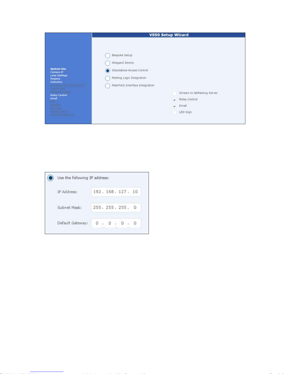
VS50 Installation Guide V1.0
Figure 5: Access Control with Stream and LED sign removed
For the purpose of this guide, the following pages will be structured around the Bespoke Setup with
all of the items checked (As per figure 4 on previous page). Parking protocols (Parking Logic &
PlateTech) will be covered at the end of the section in 7.1.15 and 7.1.16.
7.1.3 Setup Wizard – Device Setup
This page enables you to configure a new IP address for the camera. Simply fill in the IP address,
subnet and gateway (if required) as shown in Figure 6 below, then click ‘Next’.
Figure 6: Setup Wizard Device Setup
NOTE: Changing an IP address requires a reboot of the camera to commit the changes. This will be
performed automatically by the wizard after clicking the ‘Finish’ button on the final configuration
page.
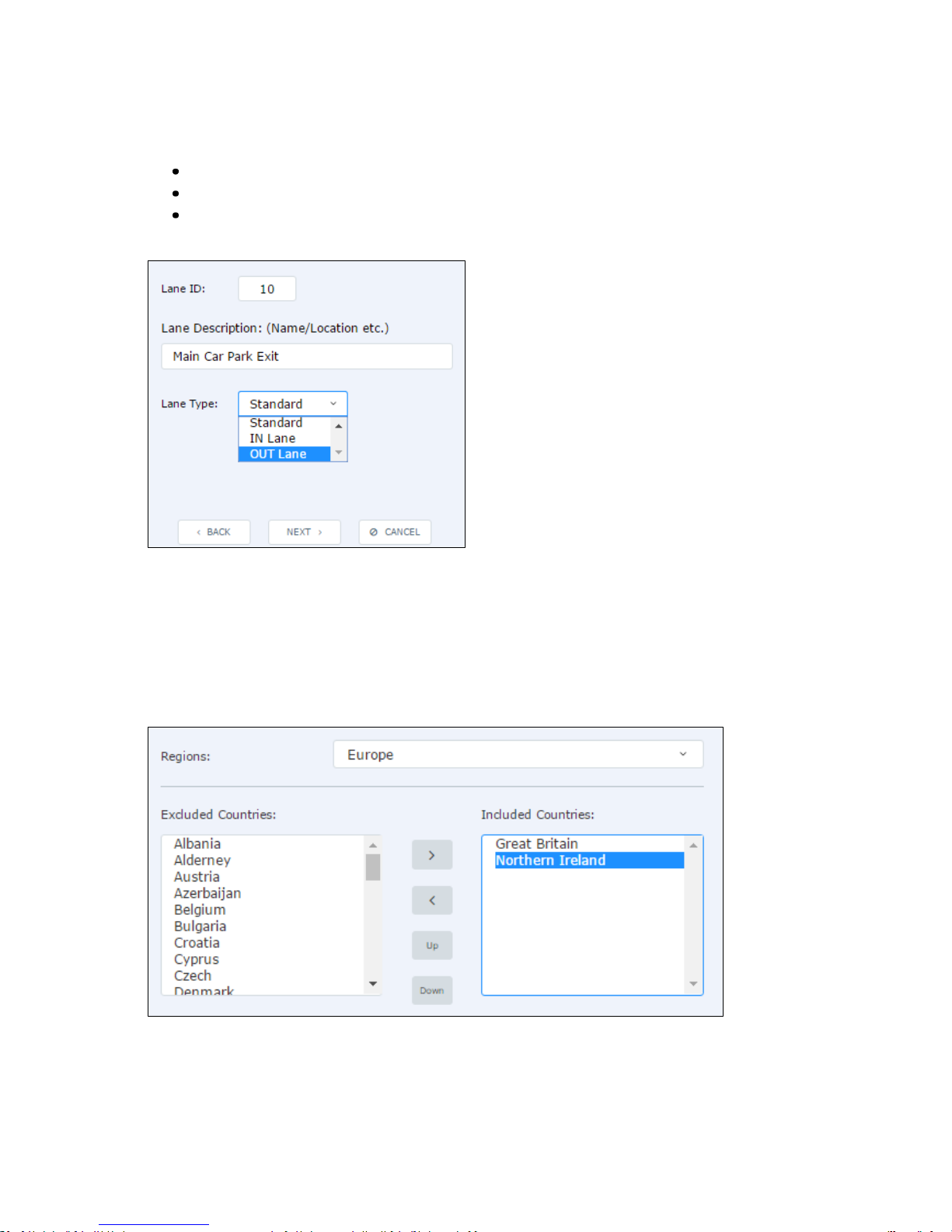
7.1.4 Setup Wizard – Lane Settings
This page configures key lane details, namely ‘Lane ID’; ‘Lane Description’ and ‘Lane Type’ (Figure 7).
Lane ID - Enter a numeric value which will act as a unique identifier for the lane. Here the lane ID
must be unique within an enclosed ANPR system.
Lane Description - Here you can input a user-friendly alphanumeric string to describe the lane type
and location. In the example below, it describes the lane as the ‘Main Car Park Exit’
VS50 Installation Guide V1.0
Lane Type - The ‘lane type’ is for use in car parking systems where you would like to monitor or
manage car park capacity and dwell-times in a JetParking Server. The options are:
In – classes all vehicles passing this camera as entering a car park
Out – classes all vehicles passing this camera as leaving a car park
Standard – No definition is given as to whether vehicles passing the camera are entering or
exiting.
Figure 7: Setup Wizard Lane Settings
Once the lane has been configured, click ‘Next’
7.1.5 Setup Wizard – Regions
The VS50 has an on-board engine capable of reading plates from all over the World. In the ‘Regions’
page, you should select the region of installation from the drop-down list and any countries which
are likely to be seen by the camera.
Figure 8: Setup Wizard Regions
Use the arrows to move countries to and from the ‘Excluded List’ and ‘Included List’.
 Loading...